EP2055769A2 - Fermentation automatique munie d'un système de contrôle - Google Patents
Fermentation automatique munie d'un système de contrôle Download PDFInfo
- Publication number
- EP2055769A2 EP2055769A2 EP09001430A EP09001430A EP2055769A2 EP 2055769 A2 EP2055769 A2 EP 2055769A2 EP 09001430 A EP09001430 A EP 09001430A EP 09001430 A EP09001430 A EP 09001430A EP 2055769 A2 EP2055769 A2 EP 2055769A2
- Authority
- EP
- European Patent Office
- Prior art keywords
- fermentation
- automatically
- determined values
- gas
- values
- Prior art date
- Legal status (The legal status is an assumption and is not a legal conclusion. Google has not performed a legal analysis and makes no representation as to the accuracy of the status listed.)
- Withdrawn
Links
- 238000000855 fermentation Methods 0.000 title claims abstract description 135
- 230000004151 fermentation Effects 0.000 title claims abstract description 135
- 238000000034 method Methods 0.000 claims abstract description 29
- 238000005259 measurement Methods 0.000 claims abstract description 18
- 238000010438 heat treatment Methods 0.000 claims abstract description 10
- 238000001816 cooling Methods 0.000 claims abstract description 8
- 230000001960 triggered effect Effects 0.000 claims abstract description 6
- 238000011156 evaluation Methods 0.000 claims description 13
- 238000012544 monitoring process Methods 0.000 claims description 13
- 238000012545 processing Methods 0.000 claims description 11
- 230000009471 action Effects 0.000 claims description 4
- 230000005540 biological transmission Effects 0.000 claims description 2
- 235000000346 sugar Nutrition 0.000 description 27
- 239000007788 liquid Substances 0.000 description 20
- 239000007789 gas Substances 0.000 description 19
- LFQSCWFLJHTTHZ-UHFFFAOYSA-N Ethanol Chemical compound CCO LFQSCWFLJHTTHZ-UHFFFAOYSA-N 0.000 description 15
- 230000004888 barrier function Effects 0.000 description 13
- CURLTUGMZLYLDI-UHFFFAOYSA-N Carbon dioxide Chemical compound O=C=O CURLTUGMZLYLDI-UHFFFAOYSA-N 0.000 description 10
- 235000014676 Phragmites communis Nutrition 0.000 description 8
- 230000003287 optical effect Effects 0.000 description 8
- 244000286779 Hansenula anomala Species 0.000 description 7
- 229910002092 carbon dioxide Inorganic materials 0.000 description 5
- 239000001569 carbon dioxide Substances 0.000 description 5
- 230000000694 effects Effects 0.000 description 4
- 239000000463 material Substances 0.000 description 4
- 230000008569 process Effects 0.000 description 4
- 238000011144 upstream manufacturing Methods 0.000 description 4
- PEDCQBHIVMGVHV-UHFFFAOYSA-N Glycerine Chemical compound OCC(O)CO PEDCQBHIVMGVHV-UHFFFAOYSA-N 0.000 description 3
- 238000012937 correction Methods 0.000 description 3
- 238000004519 manufacturing process Methods 0.000 description 3
- 239000000047 product Substances 0.000 description 3
- 230000001476 alcoholic effect Effects 0.000 description 2
- 238000009530 blood pressure measurement Methods 0.000 description 2
- 238000006243 chemical reaction Methods 0.000 description 2
- 238000004891 communication Methods 0.000 description 2
- 238000011161 development Methods 0.000 description 2
- 238000007789 sealing Methods 0.000 description 2
- 239000000126 substance Substances 0.000 description 2
- 230000000007 visual effect Effects 0.000 description 2
- 241000894006 Bacteria Species 0.000 description 1
- 101150092780 GSP1 gene Proteins 0.000 description 1
- 241000238631 Hexapoda Species 0.000 description 1
- 208000012868 Overgrowth Diseases 0.000 description 1
- 241000269400 Sirenidae Species 0.000 description 1
- 241000607479 Yersinia pestis Species 0.000 description 1
- 239000002253 acid Substances 0.000 description 1
- 150000007513 acids Chemical class 0.000 description 1
- 238000013459 approach Methods 0.000 description 1
- 235000019568 aromas Nutrition 0.000 description 1
- 235000013405 beer Nutrition 0.000 description 1
- 235000013361 beverage Nutrition 0.000 description 1
- 230000015572 biosynthetic process Effects 0.000 description 1
- 238000009529 body temperature measurement Methods 0.000 description 1
- 239000006227 byproduct Substances 0.000 description 1
- 230000015556 catabolic process Effects 0.000 description 1
- 230000008859 change Effects 0.000 description 1
- 238000004140 cleaning Methods 0.000 description 1
- 230000002950 deficient Effects 0.000 description 1
- 238000001739 density measurement Methods 0.000 description 1
- 230000001419 dependent effect Effects 0.000 description 1
- 238000001514 detection method Methods 0.000 description 1
- 238000010586 diagram Methods 0.000 description 1
- 238000009792 diffusion process Methods 0.000 description 1
- 208000037265 diseases, disorders, signs and symptoms Diseases 0.000 description 1
- 230000008030 elimination Effects 0.000 description 1
- 238000003379 elimination reaction Methods 0.000 description 1
- 239000012467 final product Substances 0.000 description 1
- 239000012530 fluid Substances 0.000 description 1
- 239000006260 foam Substances 0.000 description 1
- 238000005187 foaming Methods 0.000 description 1
- 238000007654 immersion Methods 0.000 description 1
- 238000003780 insertion Methods 0.000 description 1
- 230000037431 insertion Effects 0.000 description 1
- 238000012856 packing Methods 0.000 description 1
- 230000002093 peripheral effect Effects 0.000 description 1
- 238000003908 quality control method Methods 0.000 description 1
- 230000004044 response Effects 0.000 description 1
- 230000000717 retained effect Effects 0.000 description 1
- 230000000630 rising effect Effects 0.000 description 1
- 239000000523 sample Substances 0.000 description 1
- 235000015096 spirit Nutrition 0.000 description 1
- 150000008163 sugars Chemical class 0.000 description 1
- 230000002123 temporal effect Effects 0.000 description 1
- XLYOFNOQVPJJNP-UHFFFAOYSA-N water Substances O XLYOFNOQVPJJNP-UHFFFAOYSA-N 0.000 description 1
- 235000014101 wine Nutrition 0.000 description 1
Images



Classifications
-
- C—CHEMISTRY; METALLURGY
- C12—BIOCHEMISTRY; BEER; SPIRITS; WINE; VINEGAR; MICROBIOLOGY; ENZYMOLOGY; MUTATION OR GENETIC ENGINEERING
- C12M—APPARATUS FOR ENZYMOLOGY OR MICROBIOLOGY; APPARATUS FOR CULTURING MICROORGANISMS FOR PRODUCING BIOMASS, FOR GROWING CELLS OR FOR OBTAINING FERMENTATION OR METABOLIC PRODUCTS, i.e. BIOREACTORS OR FERMENTERS
- C12M41/00—Means for regulation, monitoring, measurement or control, e.g. flow regulation
- C12M41/44—Means for regulation, monitoring, measurement or control, e.g. flow regulation of volume or liquid level
-
- C—CHEMISTRY; METALLURGY
- C12—BIOCHEMISTRY; BEER; SPIRITS; WINE; VINEGAR; MICROBIOLOGY; ENZYMOLOGY; MUTATION OR GENETIC ENGINEERING
- C12M—APPARATUS FOR ENZYMOLOGY OR MICROBIOLOGY; APPARATUS FOR CULTURING MICROORGANISMS FOR PRODUCING BIOMASS, FOR GROWING CELLS OR FOR OBTAINING FERMENTATION OR METABOLIC PRODUCTS, i.e. BIOREACTORS OR FERMENTERS
- C12M41/00—Means for regulation, monitoring, measurement or control, e.g. flow regulation
-
- C—CHEMISTRY; METALLURGY
- C12—BIOCHEMISTRY; BEER; SPIRITS; WINE; VINEGAR; MICROBIOLOGY; ENZYMOLOGY; MUTATION OR GENETIC ENGINEERING
- C12M—APPARATUS FOR ENZYMOLOGY OR MICROBIOLOGY; APPARATUS FOR CULTURING MICROORGANISMS FOR PRODUCING BIOMASS, FOR GROWING CELLS OR FOR OBTAINING FERMENTATION OR METABOLIC PRODUCTS, i.e. BIOREACTORS OR FERMENTERS
- C12M41/00—Means for regulation, monitoring, measurement or control, e.g. flow regulation
- C12M41/12—Means for regulation, monitoring, measurement or control, e.g. flow regulation of temperature
Definitions
- the invention relates to a low-cost method and apparatus for monitoring and thermally guiding a fermentation process (fermentation control and fermentation guidance).
- Methods are also known to measure the sugar content by continuous density measurements with introduced into the fermentation sensors.
- a density probe is known, which determines the density of the digestate continuously by measuring the absolute pressure at three different measuring points in the fermentation tank.
- the absolute pressures change when the level changes or when the immersion depth in the fermentation tank changes. Since the measured pressure differences between the three measuring points are many times smaller than the changes in the absolute pressures in the cases just mentioned, this measuring method is relatively susceptible to interference and the determination of the sugar content in the must is relatively inaccurate.
- a method which determines the density of the digestate by a differential pressure measurement between two specified points and calculates therefrom the sugar or alcohol content.
- the device for differential pressure measurement can be permanently installed in the fermentation tank or even detachable.
- the measurement points are fixed, but this must be done to the tank changes (for example, by the insertion of two pipes in the tank wall), which of course causes costs.
- this method must ensure that the measurements always take place at the same vertical distance of the measuring points. Since density sensors are relatively expensive, such measuring devices are expensive. In addition, there are cleaning problems with sensors that work in the digestate - such as density sensors.
- the object of the invention is to provide a simple, maintenance-free, inexpensive and accurate method for measuring the amount of gas escaping from a fermentation tank and due From this context, the sugar breakdown, the increase in alcohol and the residual sweetness can be determined.
- the basis is the determination of the exact volume and the sugar content of the digestate at the start of fermentation.
- this object is achieved by a method with which the amount of gas escaping from the container is determined.
- a generic device is characterized by at least one measuring device for measuring the amount of gas exiting the fermentation vessel gas.
- a preferred embodiment of the method according to the invention provides for the use of a device for electronic data processing, for example a PC.
- a device for electronic data processing for example a PC.
- Gay-Lussac a corrected fermentation equations according to Gay-Lussac, in which it is taken into account that by-products such as glycerol can make up to 9% of the alcohol simply other quantities, such as the sugar level. or alcohol, and the measured and / or calculated data are stored, printed or graphically represented, for example, as proof curves.
- the invention enables a more accurate determination of the relevant size of sugar in must than has hitherto been the case.
- the software of the data processing is designed so that online corrections can be made easily. Such Corrections are necessary, for example, with fermentation disturbances, when the digestate had to be filtered and when accurate measurements were disturbed and interrupted. In such a case, the current initial parameters (sugar content and amount of fermentation) can be re-entered and the fermentation control can be restarted.
- the invention preferably provides a radio unit which transmits the determined data via radio to the radio receiver of the evaluation unit. This eliminates the costly and expensive laying of cables.
- a preferred embodiment provides that the individual measuring points are queried successively, in particular cyclically, or that a is provided by a multiplexer to query the measuring points.
- a device for processing the measured data from a plurality of measuring points is provided.
- the invention provides at least one alarm device.
- This can be an optical, acoustic, dialing and / or transmitting device.
- An alarm can thus be signaled optically, for example, by a control lamp and / or acoustically via a siren.
- the invention also provides for the possibility of telephone notification or notification via an electronic communication medium such as SMS or e-mail.
- an electronic communication medium such as SMS or e-mail.
- the alarm can be delivered to multiple receivers. This allows rapid response even at times when there is usually no one near the fermentation tank in question, for example, at night, on weekends or when a winemaker is working in the vineyard.
- the sugar content is determined continuously.
- the temperature of the exiting gas is measured according to the invention.
- This temperature is a good measure of the average temperature of the digestate because it represents the temperature in the various temperature layers in the fermentor, in contrast to the temperature otherwise measured at a single location in the tank (in the liquid).
- the latter can vary greatly locally, and generally from at least 5 ° C and up to 10 ° C.
- the reason are yeast clouds or clusters in the digestate, where a locally higher fermentation activity and thus locally higher temperature is given. Therefore, the correct temperature can not be measured in the tank itself.
- the temperature sensor is placed just above the stopper in the hole of the fermentation tank or at the end of the fermenting puddle (in the direction of digestate).
- the temperature of the fermentation product filled into the fermentation tank can be measured very quickly, before the start of fermentation.
- Particularly important is the novel measurement of the temperature of the fermentation during fermentation and during fermentation. These important data are automatically measured by the fermentation system.
- the temperature measured according to the invention is also the basis for the required temperature correction of the gas volume measured in each case and also the fermentation by heating or cooling.
- predetermined fermentation curves can be used, which represent an ideal temporal fermentation behavior. Accordingly, from the temperature and the exiting gas volume, the amount of substance produced during a fermentation process carbon dioxide can be determined. Furthermore, it can be provided that from the escaping Substance of carbon dioxide for a fermentation control important values are determined, such as, for example, the sugar decrease and the increase in alcohol in the fermentation or the residual sweetness of the fermentation product.
- the temperature can be used for fermentation. It is possible to influence the temperature of the fermentation material from the outside so that on the one hand it is so high that fermentation can take place and, on the other hand, it is not so high that aromas are removed from the digestate with the escaping gas into the environment, resulting in a loss of aroma of the final product.
- Such a fermentation means that the temperature is adapted to the course of the fermentation curve. This is (relatively) straightforward.
- the temperature control in the course of fermentation is done by software. After that no expensive control cabinet is required.
- the sugar content is continuously determined, wherein, in particular, when a predetermined residual sugar is reached, a process is carried out, such as an acoustic or optical signal or a fermentation stop being triggered.
- An advantageous embodiment of the device according to the invention provides an interface on the measured data processing device.
- the interface makes it possible to provide the important data for a fermentation guidance, for example the temperature of the digestate.
- a control unit connected to this interface can thus influence the fermentation process from outside, for example by heating or cooling the tank. According to the invention, therefore, the processing measured data from several tanks with one computer.
- the invention provides, in particular, that a volumetric flow measurement takes place between the fermentation vessel and the fermentation pound, wherein a device has a flow meter, in particular in a gas pipeline leading from the fermenting vessel, optionally between the fermentation vessel and the fermentation pound.
- This flow measuring device is used in particular for larger flow rates.
- a further development of this embodiment provides that the flow is measured by the voltage difference between a sensor arranged upstream and downstream of a heater, or that the flowmeter has two sensors and a heater and one sensor is arranged upstream and downstream of the heater and one device is provided for measuring the voltage difference of the sensors.
- the invention provides that escaping for determination Gas quantities, the stroke frequency of a movable lid of a Gärspunds is measured, wherein a preferred embodiment of the device is characterized by a measuring device for measuring the frequency of a movable bung lid of Gärspunds. From the stroke frequency, taking into account the geometry of the fermentation bung and the lifting height, it is possible to determine the total volume in a specific time interval. In conjunction with a temperature measurement of the exiting gas can be calculated from the gas volume, the Zuckerab- or alcohol increase and the residual sweetness in the digestate.
- the measurement of the stroke frequency can be done in many ways, but the invention provides for two preferred methods of doing so: the first is an optical measurement, such as one with the aid of a light barrier attached to the main body of the fermentation bung.
- the light barrier is interrupted by a "flag" attached to the movable lid of the fermentation pint when the lid is in its lower position. If the lid moves upwards, the space between the light barrier becomes free.
- the measurement can also be done electrically, such as via a switch which is attached to the upper edge of the Gärspund ground stresses. If the movable lid is in its lower position, the switch is closed, for example, the lid moves upwards, so the switch is opened, for example.
- the maximum amount is given by the overflow present at the fermentation pile, the minimum amount of liquid is monitored and there is an alarm if it falls below this limit. This is preferably done by a component for monitoring the minimum liquid level in the fermentation puddle, such as a reed contact. If there is less liquid in the fermentation bung, a donor (magnet) located on the feeding plug cover will more closely approximate a reed sensor located at the bottom of the feeding pest and cause a signal.
- the level is measured in the fermentation vessel, by a level gauge. This is particularly important when using temperature-dependent resistors as flow measuring sensors, as they are the subject of claims 18 and 29, since they can be destroyed by liquid.
- a visual or audible signal or the feeding of the fermentation material are automatically stopped in the fermentation vessel. So should be present at the beginning of the fermentation between the surface of the fermentation in the fermentation vessel and the bunghole a so-called rising space of at least 1/10 of the total fermentation tank contents.
- this prevents fermentation material or fermentation foam from escaping through the fermentation puddle during the high fermentation phase, with the consequence of impairing the aseptic action of the barrier liquid in the fermentation puddle.
- the Fig. 1 shows a fermentation tank A, arranged on the upper side of a pipe 15 with a flow meter 16 is.
- the pipeline opens into a fermentation bung having a double-cylindrical main body 2 and a bung lid 8, between which a further measuring device for flow measurement 18 is arranged.
- a level gauge 30 On the side of the container A or tank for fermentation, a level gauge 30 is arranged, which has a three-way cock 32 with the interior of the container A in fluid communication or bringable vertical transparent tube 31 and in the upper region of a level sensor 33 in the range of a desired filling level is arranged.
- the container size is selected or the container is filled so that it is only about 2/3 filled so that foaming is avoided by the fermentation.
- the fermentation puddle 1 according to the invention is also fastened by means of a plug 4 in an opening in the tank and fulfills all the functions known from conventional fermenting ponds. Among other things, these are the shielding of the digestate to the outside, so that no harmful bacteria, yeasts or insects can get into the tank. In addition, a fermentation pound allows the expulsion of gases from the tank interior, so that when fermenting an overpressure in the tank is prevented.
- the fermentation puddle 1 has a double-cylindrical main body 2 with an outer and an inner wall 2a, 2b, which has a tapered inlet 3, which is surrounded by an elastic plug 4, by means of which the Gsp 1 can be placed at the outlet of a fermentation tank.
- an outlet 5 is provided for the outlet of superfluous sealing liquid, which is filled between the two walls 2a, 2b of the main body 2.
- a temperature sensor 6 Located above the plug 4 is located at the inlet 3, a side nozzle. 7
- the main body 2 can be found at 1. a vertically movable, at 1.a tiltable about a horizontal hinge cylindrical, closed on the top bung cover 8, the cylinder wall 8a projects into the space between the inner and outer cylinder wall 2a, 2b of the main body 2 and whose diameter corresponds approximately to the mean value of the diameters of the two cylinder walls 2a, 2b of the main body 2.
- a flag 9 is arranged laterally, which projects between one or two light barriers 10 in a measuring and transmitting housing 11, in which also the temperature value measured by the temperature sensor 6 is removed.
- the measuring and transmitting housing 7 includes in the illustrated embodiment, a radio module 12, with which the collected data to a further processing device, such as a PC, can be transmitted for further processing.
- a (not shown) fermentation vessel or a tank has at its top an outlet 13, from which extends to the fermentation a variable, the quite different mounting positions oncoming pipeline 14, in which a flow meter 16 is arranged, which is in particular designed such that he has arranged in the flow direction one behind the other two sensors, between which a heater is provided.
- the flow meter 16 is associated with electronics, which is arranged in the illustrated embodiment around the tube 14 and the flow meter 16 around, this takes from the two sensors from voltage signals. If a flow through the pipe 14 takes place, the voltage difference between the two sensors due to the different temperature caused by the heater (upstream cooler, downstream warmer) depends on the flow rate and thus the flow rate and proportional to this.
- a temperature sensor 17 is arranged to measure the temperature of the exiting gas from the fermenter, since this is needed for example to obtain the flow rate from the measured flow volume.
- the temperature sensor can also be arranged downstream of the flow meter 16, since the heating in the latter is minimal due to the lower heating power of the flow measuring sensors and hardly influences the measurement of the basic temperature of the gas leaving the fermenting vessel.
- 2 barrier liquid locks 2d, 2e, by means of which the entrained barrier liquid is retained and flows back into the fermentation puddle at the top of the Gärspundgefäßes.
- the Fig. 4 shows an overall view with two schematically illustrated outlets and Gärspunden for two fermenters. All measuring points are led to a multiplexer 20 and connected via this to an evaluation device 21 in the form of a computer, which is provided with peripheral devices, such as an input keyboard 22 with mouse 23 and a screen 24.
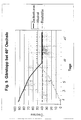
- the evaluation device is designed to evaluate the measured data, in particular to determine the sugar decrease and the alcohol content on the basis of the measured CO 2 flow and the temperature. With in her input initial sweetness can be due to the determined sugar decrease determine the respective sugar content. Alcohol and sugar content are in the Fig. 5 shown. There may be a desired residual sweetness in the processing unit, such as in Fig. 5 be adjusted by 40 ° Oechsle. If the sugar content reaches this residual sweetness, a signal can be emitted visually and / or acoustically, as a result of which a fermentation stop can be initiated. Also, when the desired residual sweetness is reached, a fermentation stop can be initiated automatically, for example by interrupting heating and / or by cooling the fermentation product.
- Fig. 6 shows a side view of a detail view of the level measurement 30.
- This has, as already stated, a transparent tube 31 and a level sensor 33.
- the tube 31 is supported by a support plate 34 arranged on the back side thereof between the tube 31 and the container A, which surrounds the tube 31 in a semicircular or Q-shape and on whose side cheeks 35 a scale 36 is arranged.
- the level sensor 33 has a float located in the tube 31 37, which carries a transmitter 38, which in the illustrated embodiment of FIGS. 6 and 6a for example, a magnet. Laterally of the tube 33, a detector 39 is disposed on the support plate 34, which is a reed detector in the illustrated embodiment. The detector 39 is held on the support plate 34 by a holder 40, which in the illustrated embodiment of FIGS. 6 and 6a is formed as a cross-sectionally U-shaped bracket, which carries a clamping screw 41, with which the detector 39 can be clamped to the desired filling level height on the carrier 34.
- the transmitter 38 carried by the float 37 is an opaque body.
- the detector 39 is designed as an optical detector, which, as in Fig. 7a is shown, the tube 38 and thus the encoder surrounds a U-shaped and has a light source and an optical receiver (not shown), so that upon reaching the level in which the level sensor 30 is disposed, the light path from the light source to the light receiver the encoder 38 is interrupted.
- the level sensor is in this embodiment of Fig. 7 and 7a fastened in the same way to the carrier 34, as with reference to the FIGS. 6 and 6a has been described.
- Fig. 8 becomes a detector, which likewise, like with the FIGS. 6 and 6a a magnetic detector in the form of a reed contact, held by two the tube 34 each semi-circular surrounding plates 42 which are braced by two on both sides of the tube 34 arranged screws 43 with the tube.
- the holder is formed in the same manner as in the embodiment of Fig. 8 and 8a ,
- the detector device 39 is again formed as an optical detector device with diagonally opposite, each arranged in a semicircular formation of one of the plates 42 light emitter and light receiver, the light path between these in turn formed by the trained in the form of an opaque body encoder 38 upon reaching the set level is interrupted.
- the detectors 39 can be connected via a line 44 to the evaluation device 21 (FIG. Fig. 4 ). Upon reaching the set and desired level, a signal, such as a visual or audible signal, can be output. By the evaluation device, a valve in a supply line to the container A (not shown) can be closed automatically.
Landscapes
- Chemical & Material Sciences (AREA)
- Wood Science & Technology (AREA)
- Health & Medical Sciences (AREA)
- Life Sciences & Earth Sciences (AREA)
- Engineering & Computer Science (AREA)
- Bioinformatics & Cheminformatics (AREA)
- Organic Chemistry (AREA)
- Zoology (AREA)
- Biochemistry (AREA)
- Genetics & Genomics (AREA)
- Analytical Chemistry (AREA)
- Microbiology (AREA)
- General Engineering & Computer Science (AREA)
- Biotechnology (AREA)
- General Health & Medical Sciences (AREA)
- Sustainable Development (AREA)
- Biomedical Technology (AREA)
- Physics & Mathematics (AREA)
- Thermal Sciences (AREA)
- Apparatus Associated With Microorganisms And Enzymes (AREA)
- Micro-Organisms Or Cultivation Processes Thereof (AREA)
- Processing Of Solid Wastes (AREA)
Applications Claiming Priority (3)
| Application Number | Priority Date | Filing Date | Title |
|---|---|---|---|
| DE200510015530 DE102005015530A1 (de) | 2005-04-04 | 2005-04-04 | Verfahren und Vorrichtung zum Überwachen eines Gärvorgangs |
| DE102005028556A DE102005028556A1 (de) | 2005-04-04 | 2005-06-21 | Verfahren und Vorrichtung zum Überwachen eines Gärvorgangs |
| EP06007013A EP1710298B1 (fr) | 2005-04-04 | 2006-04-01 | Fermentation automatique munie d'un système de contrôle |
Related Parent Applications (1)
| Application Number | Title | Priority Date | Filing Date |
|---|---|---|---|
| EP06007013A Division EP1710298B1 (fr) | 2005-04-04 | 2006-04-01 | Fermentation automatique munie d'un système de contrôle |
Publications (2)
| Publication Number | Publication Date |
|---|---|
| EP2055769A2 true EP2055769A2 (fr) | 2009-05-06 |
| EP2055769A3 EP2055769A3 (fr) | 2009-06-24 |
Family
ID=36600151
Family Applications (2)
| Application Number | Title | Priority Date | Filing Date |
|---|---|---|---|
| EP06007013A Expired - Lifetime EP1710298B1 (fr) | 2005-04-04 | 2006-04-01 | Fermentation automatique munie d'un système de contrôle |
| EP09001430A Withdrawn EP2055769A3 (fr) | 2005-04-04 | 2006-04-01 | Fermentation automatique munie d'un système de contrôle |
Family Applications Before (1)
| Application Number | Title | Priority Date | Filing Date |
|---|---|---|---|
| EP06007013A Expired - Lifetime EP1710298B1 (fr) | 2005-04-04 | 2006-04-01 | Fermentation automatique munie d'un système de contrôle |
Country Status (5)
| Country | Link |
|---|---|
| EP (2) | EP1710298B1 (fr) |
| AT (1) | ATE439425T1 (fr) |
| DE (2) | DE102005028556A1 (fr) |
| ES (1) | ES2330242T3 (fr) |
| PT (1) | PT1710298E (fr) |
Families Citing this family (6)
| Publication number | Priority date | Publication date | Assignee | Title |
|---|---|---|---|---|
| DE102007047175C5 (de) | 2007-10-02 | 2015-04-02 | Marko Hörner | Verfahren und Vorrichtung zum Überwachen eines Gärvorgangs |
| DE202008011610U1 (de) | 2008-08-30 | 2009-10-22 | Alber, Bernd, Dr. | Vorrichtung zum Überwachen eines Gärvorganges |
| ITTV20120149A1 (it) * | 2012-07-30 | 2014-01-31 | L A S I S R L | Fermentatore migliorato |
| DE102017103536A1 (de) | 2017-02-21 | 2018-08-23 | Abb Schweiz Ag | Vorrichtung und Verfahren zur Kontrolle der Fermentierung eines organischen Produkts |
| WO2022219205A1 (fr) | 2021-04-14 | 2022-10-20 | Talleres Ruiz S.A. | Processus et dispositif de surveillance en continu et commande automatique améliorée de température, et d'aération-oxygénation, du procédé de fermentation alcoolique dans le vin par des techniques d'émission acoustique |
| CN114814128A (zh) * | 2022-04-27 | 2022-07-29 | 学林苑(深圳)葡萄酒文化有限公司 | 一种葡萄酒发酵在线实时监测系统 |
Citations (6)
| Publication number | Priority date | Publication date | Assignee | Title |
|---|---|---|---|---|
| DE451176C (de) | 1926-05-11 | 1927-10-17 | Wagner Otto | Verfahren zum Regeln des Spundungsdrucks |
| DE1432993A1 (de) | 1965-09-11 | 1969-10-30 | Columbia Internat Corp Gmbh | Spund fuer Faesser oder Behaelter |
| DE1965070A1 (de) | 1969-12-27 | 1971-07-01 | Wilhelm Meier Brauereimaschine | Spundapparat |
| JPS57144097A (en) | 1981-03-04 | 1982-09-06 | Hitachi Kiden Kogyo Ltd | Device for measuring fermentation characteristic of object to be fermented in fermentation vessel |
| US5204262A (en) | 1990-03-01 | 1993-04-20 | Meiering Anton G | Ethanol sensor for computerized fermentation control |
| EP1270716A1 (fr) | 2001-06-29 | 2003-01-02 | Stephan Dipl.-Ing. Licht | Procédé pour la surveillance et la régulation d'un procédé de fermentation |
Family Cites Families (4)
| Publication number | Priority date | Publication date | Assignee | Title |
|---|---|---|---|---|
| US3926738A (en) * | 1972-05-10 | 1975-12-16 | Wilson John D | Method and apparatus for control of biochemical processes |
| US4680267A (en) * | 1985-03-01 | 1987-07-14 | New Brunswick Scientific Company, Inc. | Fermentor control system |
| ATA35095A (de) * | 1995-02-27 | 1996-08-15 | Frings & Co Heinrich | Messvorrichtung für einen von wenigstens zwei flüchtigen bestandteilen einer flüssigkeit, insbesondere einer fermentationsflüssigkeit |
| AT4855U3 (de) * | 2001-09-28 | 2002-10-25 | Stingel Itt Oeg | Verfahren und vorrichtung zum behandeln von maische |
-
2005
- 2005-06-21 DE DE102005028556A patent/DE102005028556A1/de not_active Ceased
-
2006
- 2006-04-01 DE DE502006004480T patent/DE502006004480D1/de not_active Expired - Lifetime
- 2006-04-01 EP EP06007013A patent/EP1710298B1/fr not_active Expired - Lifetime
- 2006-04-01 EP EP09001430A patent/EP2055769A3/fr not_active Withdrawn
- 2006-04-01 AT AT06007013T patent/ATE439425T1/de active
- 2006-04-01 ES ES06007013T patent/ES2330242T3/es not_active Expired - Lifetime
- 2006-04-01 PT PT06007013T patent/PT1710298E/pt unknown
Patent Citations (6)
| Publication number | Priority date | Publication date | Assignee | Title |
|---|---|---|---|---|
| DE451176C (de) | 1926-05-11 | 1927-10-17 | Wagner Otto | Verfahren zum Regeln des Spundungsdrucks |
| DE1432993A1 (de) | 1965-09-11 | 1969-10-30 | Columbia Internat Corp Gmbh | Spund fuer Faesser oder Behaelter |
| DE1965070A1 (de) | 1969-12-27 | 1971-07-01 | Wilhelm Meier Brauereimaschine | Spundapparat |
| JPS57144097A (en) | 1981-03-04 | 1982-09-06 | Hitachi Kiden Kogyo Ltd | Device for measuring fermentation characteristic of object to be fermented in fermentation vessel |
| US5204262A (en) | 1990-03-01 | 1993-04-20 | Meiering Anton G | Ethanol sensor for computerized fermentation control |
| EP1270716A1 (fr) | 2001-06-29 | 2003-01-02 | Stephan Dipl.-Ing. Licht | Procédé pour la surveillance et la régulation d'un procédé de fermentation |
Also Published As
| Publication number | Publication date |
|---|---|
| DE102005028556A1 (de) | 2007-01-04 |
| DE502006004480D1 (de) | 2009-09-24 |
| EP1710298B1 (fr) | 2009-08-12 |
| EP1710298A1 (fr) | 2006-10-11 |
| PT1710298E (pt) | 2009-10-15 |
| ES2330242T3 (es) | 2009-12-07 |
| ATE439425T1 (de) | 2009-08-15 |
| EP2055769A3 (fr) | 2009-06-24 |
Similar Documents
| Publication | Publication Date | Title |
|---|---|---|
| DE102007047175B4 (de) | Verfahren und Vorrichtung zum Überwachen eines Gärvorgangs | |
| EP1359398B1 (fr) | Méthode pour la détermination du niveau actuel d'un liquide dans un réservoir | |
| EP2166336B1 (fr) | Procédé de surveillance de la qualité d'un carburant contenant de l'alcool dans un réservoir de stockage | |
| DE29825190U1 (de) | Vorrichtung zur Volumenbestimmung | |
| EP2065685A2 (fr) | Dispositif et procédé de mesure du niveau de remplissage d'un aliment liquide dans un récipient | |
| EP2528850A1 (fr) | Procédé et système de remplissage sous pression de récipients | |
| EP1710298B1 (fr) | Fermentation automatique munie d'un système de contrôle | |
| DE10131158A1 (de) | Verfahren zur kontinuierlichen Überwachung und Regelung von Gärprozessen | |
| EP0617789B1 (fr) | Procede et dispositif de prelevement d'un echantillon representatif de lait | |
| DE69927290T2 (de) | Bioverschmutzungsüberwachungsvorrichtung und verfahren zur überwachung oder zur feststellung von bioverschmutzung | |
| EP2482045B1 (fr) | Procédé de détection de la capacité de remplissage d'un récipient de déchets d'appareils de lavage à microplaques | |
| DE102005015530A1 (de) | Verfahren und Vorrichtung zum Überwachen eines Gärvorgangs | |
| EP0375863B1 (fr) | Procédé pour l'emballage de la bière | |
| EP4012356B1 (fr) | Procédé de détermination d'un niveau de remplissage, capteur à ultrasons et dispositif de mesure permettant de déterminer un volume d'un produit de remplissage | |
| WO2023051945A1 (fr) | Procédé et système d'étalonnage de mesure de débit | |
| DE2634971C2 (de) | Einrichtung zur kontinuierlichen Bestimmung des Kohlendioxidgehaltes einer durch eine Leitung strömenden Flüssigkeit, insbesondere eines Getränkes | |
| EP2524080A1 (fr) | Convertisseur de mesure pour la détection de formation de mousse sur un liquide | |
| EP3837508B1 (fr) | Procédé pour l'étalonnage in situ d'un appareil de mesure de niveau et module d'étalonnage in situ | |
| DE102011114580B4 (de) | Verfahren und Vorrichtung zur automatischenGärkontrolle und/oder Gärführung | |
| EP2455727A1 (fr) | Séparateur de matière légère | |
| DE20110719U1 (de) | Vorrichtung zur Überwachung und Regelung von Gärprozessen | |
| CN214877317U (zh) | 一种具有警报功能的酒精罐 | |
| CN216533784U (zh) | 烟丝加香系统和烟丝加工设备 | |
| DE2462281A1 (de) | Vorrichtung zum eichen der empfindlichkeit eines sensorelementes | |
| DE3039608C2 (fr) |
Legal Events
| Date | Code | Title | Description |
|---|---|---|---|
| PUAI | Public reference made under article 153(3) epc to a published international application that has entered the european phase |
Free format text: ORIGINAL CODE: 0009012 |
|
| 17P | Request for examination filed |
Effective date: 20090302 |
|
| AC | Divisional application: reference to earlier application |
Ref document number: 1710298 Country of ref document: EP Kind code of ref document: P |
|
| AK | Designated contracting states |
Kind code of ref document: A2 Designated state(s): AT BE BG CH CY CZ DE DK EE ES FI FR GB GR HU IE IS IT LI LT LU LV MC NL PL PT RO SE SI SK TR |
|
| PUAL | Search report despatched |
Free format text: ORIGINAL CODE: 0009013 |
|
| AK | Designated contracting states |
Kind code of ref document: A3 Designated state(s): AT BE BG CH CY CZ DE DK EE ES FI FR GB GR HU IE IS IT LI LT LU LV MC NL PL PT RO SE SI SK TR |
|
| 17Q | First examination report despatched |
Effective date: 20100119 |
|
| AKX | Designation fees paid |
Designated state(s): AT BE BG CH CY CZ DE DK EE ES FI FR GB GR HU IE IS IT LI LT LU LV MC NL PL PT RO SE SI SK TR |
|
| STAA | Information on the status of an ep patent application or granted ep patent |
Free format text: STATUS: THE APPLICATION IS DEEMED TO BE WITHDRAWN |
|
| 18D | Application deemed to be withdrawn |
Effective date: 20161101 |