EP2055816B1 - Vorrichtung zur Aufrechterhaltung der Kräuselung von Textilfasern oder Fäden während der späteren Fixierbehandlung - Google Patents
Vorrichtung zur Aufrechterhaltung der Kräuselung von Textilfasern oder Fäden während der späteren Fixierbehandlung Download PDFInfo
- Publication number
- EP2055816B1 EP2055816B1 EP08305706.7A EP08305706A EP2055816B1 EP 2055816 B1 EP2055816 B1 EP 2055816B1 EP 08305706 A EP08305706 A EP 08305706A EP 2055816 B1 EP2055816 B1 EP 2055816B1
- Authority
- EP
- European Patent Office
- Prior art keywords
- rails
- threads
- fixing
- perforated conveyor
- sliver
- Prior art date
- Legal status (The legal status is an assumption and is not a legal conclusion. Google has not performed a legal analysis and makes no representation as to the accuracy of the status listed.)
- Not-in-force
Links
- 239000004753 textile Substances 0.000 title claims description 53
- 238000000034 method Methods 0.000 claims description 9
- 230000008569 process Effects 0.000 claims description 8
- 238000011084 recovery Methods 0.000 claims description 5
- 238000001816 cooling Methods 0.000 claims description 3
- 238000006073 displacement reaction Methods 0.000 claims description 2
- 238000004519 manufacturing process Methods 0.000 claims description 2
- 238000013519 translation Methods 0.000 claims description 2
- 206010000496 acne Diseases 0.000 claims 1
- 230000000284 resting effect Effects 0.000 claims 1
- 239000000835 fiber Substances 0.000 description 41
- 239000011324 bead Substances 0.000 description 16
- 238000002788 crimping Methods 0.000 description 9
- 230000000694 effects Effects 0.000 description 4
- 239000000463 material Substances 0.000 description 4
- 238000012545 processing Methods 0.000 description 3
- 206010003830 Automatism Diseases 0.000 description 1
- 230000008859 change Effects 0.000 description 1
- 210000000078 claw Anatomy 0.000 description 1
- 230000006835 compression Effects 0.000 description 1
- 238000007906 compression Methods 0.000 description 1
- 230000007547 defect Effects 0.000 description 1
- 230000006866 deterioration Effects 0.000 description 1
- 239000012530 fluid Substances 0.000 description 1
- 238000007710 freezing Methods 0.000 description 1
- 230000008014 freezing Effects 0.000 description 1
- 238000009998 heat setting Methods 0.000 description 1
- 238000010438 heat treatment Methods 0.000 description 1
- 238000012423 maintenance Methods 0.000 description 1
- 238000012986 modification Methods 0.000 description 1
- 230000004048 modification Effects 0.000 description 1
- 230000000750 progressive effect Effects 0.000 description 1
- 230000009467 reduction Effects 0.000 description 1
- 235000013580 sausages Nutrition 0.000 description 1
- 238000000926 separation method Methods 0.000 description 1
- 238000006467 substitution reaction Methods 0.000 description 1
- 230000008961 swelling Effects 0.000 description 1
- 230000001360 synchronised effect Effects 0.000 description 1
- 230000009466 transformation Effects 0.000 description 1
- 238000000844 transformation Methods 0.000 description 1
Images


Classifications
-
- D—TEXTILES; PAPER
- D02—YARNS; MECHANICAL FINISHING OF YARNS OR ROPES; WARPING OR BEAMING
- D02G—CRIMPING OR CURLING FIBRES, FILAMENTS, THREADS, OR YARNS; YARNS OR THREADS
- D02G1/00—Producing crimped or curled fibres, filaments, yarns, or threads, giving them latent characteristics
- D02G1/12—Producing crimped or curled fibres, filaments, yarns, or threads, giving them latent characteristics using stuffer boxes
-
- D—TEXTILES; PAPER
- D02—YARNS; MECHANICAL FINISHING OF YARNS OR ROPES; WARPING OR BEAMING
- D02J—FINISHING OR DRESSING OF FILAMENTS, YARNS, THREADS, CORDS, ROPES OR THE LIKE
- D02J13/00—Heating or cooling the yarn, thread, cord, rope, or the like, not specific to any one of the processes provided for in this subclass
Definitions
- the present invention relates to the field of the textile industry, in particular the treatment of yarns, in particular crimping texturing and relates to a device for maintaining the crimping of textile fibers or yarns during the subsequent fixing process.
- the curling of textile fibers by means of a curling machine has been known for a long time and consists of crimping the fibers or textile threads by means of a curling machine and to deposit the threads or fibers in the form of a bead continuous loops on a conveyor belt. Then, the obtained bead is subjected to a fixing operation, during which the crimp is made permanent for subsequent operations of processing the yarn or fibers.
- threads and fibers have a residual stiffness which has the effect of causing partial loosening of the loops obtained at the exit of the curling machine and during their transport to the downstream fixing machine, as well as during their treatment in this machine. last.
- FR-A-1,192,453 and by FR-A-2,681,342 devices provided in extension of a curling machine and for maintaining the curl, or by forced guidance of the son or textile fiber bead in a heat-setting oven or other fixing device, between conveyor belts tending to tighten said sausage during transport in the oven or other ( FR-A-1,192,453 ), or by forced accompaniment of the series of turns forming the coil, in order to prevent said turns from losing part of the acquired deformation, by lengthening during their treatment course in the oven or other fixing device ( FR-A-2,681,342 ).
- the strands are compressed between two perforated conveyor belts passing through the furnace or other fixing device, so that they can not undergo any vertical deformation by swelling.
- the turns undergo a drive through claws maintaining substantially their spacing and their shape during the passage of the oven or the fixing device.
- US-A-3,354,511 describes the treatment of natural fibers which have very little shrinkage due to the temperature of the treatment fluid.
- the present invention aims to overcome these disadvantages by providing a device for maintaining the crimp of textile fibers or son during the subsequent fixing process to fully guarantee the maintenance of the initial deformation of textile fibers or son.
- this device which comprises two perforated conveyor belts, between which is fed the coil of son or textile fibers from the curling machine and which pass through a fixing oven or other fixing machine to end on a wire recovery range, is characterized in that it is provided with a means for maintaining the continuity of the pressure on the bead of son or textile fibers in exit of the curling machine and during the entire fixing operation, this means cooperating with the perforated conveyor belts.
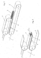
- FIG 1 of the accompanying drawings schematically shows a crimping and fixing son processing line comprising a curling machine 1 whose output is connected to a device for maintaining the crimping of textile fibers or yarns during the subsequent fixing process, which comprises two perforated conveyor belts 2, between which is fed the coil of son or textile fibers 3 from the curling machine 1 and which pass through a fixing furnace 4 or other fixing machine to end on a son recovery range 5.
- the device for maintaining the crimping of textile fibers or yarns during the subsequent fixing process is provided with a means 6 for maintaining the continuity of the pressure on the bead of threads or textile fibers 3 at the outlet of the machine. curl 1 and during the entire fixing operation, this means cooperating with the perforated conveyor belts 2.
- the means 6 for maintaining the continuity of the pressure on the bead of threads or textile fibers 3 at the outlet of the curling machine 1 and during the entire fixing operation is in the form of a pair of rails 6 'disposed between the perforated conveyor belts 2, on either side of the yarn or textile fiber bead 3.
- These rails 6' extend from the output of the curling machine 1 over the entire length of the machine. crossing the fixing furnace 4 or other fixing machine.
- These rails 6 ' can be fixed on the support frame of the perforated conveyor belts 2 by means of supports integral with the latter. These supports are not shown in detail in the accompanying drawings but their constitution is of a type perfectly accessible to those skilled in the art and does not require additional description.
- the rails 6 ' can be adjusted in position between the conveyor belts 2, in the direction of a coming together and / or spacing, by adjustable mounting on the supports integral with the support frame of the Perforated conveyor belts 2.
- adjustable mounting can be achieved by operating pneumatic cylinders controlled from a control panel or by a programmable controller or by means of mechanical adjustment devices of the threaded spindle and nut type.
- Such compensation may be necessary in the case of heat treatment having the effect of causing a withdrawal of fibers or son. Indeed, a compensation defect would have the effect of reducing the pressure on the coil and thus allow undesired deformation of the turns forming this coil.
- FIGS. 4 to 6 appended drawings show a second embodiment of the invention in which the means 6 for maintaining the continuity of the pressure on the coil of son or textile fibers 3 at the output of the curling machine 1 and during the entire operation fixing is presented in the form of two pairs of guillotine rails 61, 62 disposed between the perforated conveyor belts 2, on either side of the yarn or textile fiber bundle 3, and at least one of the conveyor belts 2 being movable in a vertical plane relative to the other.
- a pair of these rails 61 is connected to the support frame of the upper perforated conveyor belt 2 and the other pair of rails 62 is connected to the support frame of the perforated lower conveyor belt 2.
- the pairs of rails 61 and 62 have identical profiles and each comprise a horizontal support flange on the corresponding perforated conveyor belt 2 of constant width and a vertical wing of variable height linearly from one end to the other, these rails 61 and 62 being disposed on either side of the bead of threads or textile fibers 3 in an inverted manner and being guided with friction of their adjacent vertical wings ( figure 4 to 6 ) by means of not shown supports provided on the corresponding frames of the perforated conveyor belts 2.
- the upper perforated conveyor belt 2 is advantageously movably mounted on its support frame in a vertical plane relative to the lower conveyor belt 2, this mobility being conferred by the provision of connecting cylinders acting on the ends of said conveyor belt 2 between the
- FIGS. 4 to 6 appended drawings represent respectively a minimum position of spacing of the rails 61, 62 corresponding to the realization of a maximum pressure over the entire length of the son son or textile fibers 3, a maximum separation of the rails 61, 62 corresponding to a pressure minimum and constant on the yarn or textile fiber bead 3 and a progressive reduction position of the height of the bead of yarn or textile fibers 3.
- the pairs of rails 61, 62 may be mounted on the support frames of the perforated conveyor belts 2, so as to be movable transversely to the longitudinal axis of these perforated conveyor belts 2.
- each pair of rails 61 - 62 of the two pairs of rails 61, 62 on each side, integral in translation, one of the rails 61 or 62 being provided with a transverse displacement means in the form of jacks acting preferably at its ends, these jacks being connected to the support frame of the rails 61 or rails 62.
- the Figures 7 to 9 show a third embodiment of the invention, wherein the means 6 for maintaining the continuity of the pressure on the bead of son or textile fibers 3 at the output of the curling machine 1 and during all the Fixing operation is in the form of a pair of lateral continuous trainers 600 extending on either side of the yarn or textile fiber bead 3, between the perforated conveyor belts 2. These lateral continuous trainers 600 are in the form of toothed or spiked smooth belts.
- these lateral continuous trainers 600 can also be mounted movably between the perforated conveyor belts 2 by mounting the bearings of their idler pulley on moving means with mechanical, hydraulic or pneumatic cylinders.
- the driving speed of the perforated conveyor belts 2 can be adjusted according to the speed of production of the yarn or textile fiber rod 3 of the curling machine 1 via an automation, not shown, taking into account the pressure exerted on the flange in the fixing furnace 4 or other fixing machine.
- an automation not shown
- the movement control of the rails 6 ', 61, 62 or lateral continuous drives 600, in the sense of a control of the pressure exerted on the yarn or textile fiber bead 3 can also be managed via an automatism taking into account different parameters that can be measured or evaluated during the course of the yarn roll or textile fibers 3.
- the device may, at the outlet of the fixing furnace 4 or other fixing machine, pass through a cooling zone 7 before reaching the son recovery zone 5.
- a cooling zone the strand of son or textile fibers 3 is subjected to a circulation of air or another cold or refrigerated gas, which has the effect of causing additional or accentuated freezing of the deformation imparted. to textile threads or fibers.
- the invention it is possible to perform a crimping son or textile fibers which remain perfectly maintained over time, without risk of deterioration, so that the curly yarn obtained at the output of a crimping line provided with the device according to the invention is perfectly homogeneous.
Landscapes
- Engineering & Computer Science (AREA)
- Textile Engineering (AREA)
- Mechanical Engineering (AREA)
- Treatment Of Fiber Materials (AREA)
- Yarns And Mechanical Finishing Of Yarns Or Ropes (AREA)
Claims (18)
- Vorrichtung zur Aufrechterhaltung der Kräuselung von Textilfasern oder Garnen während der abschließenden Fixierbehandlung, die in einer Behandlungsstrecke der Garne durch Kräuseln und Fixieren angeordnet ist und eine Kräuselmaschine (1) umfasst, wobei die Vorrichtung mit dem Ausgang der Kräuselmaschine (1) verbunden ist und zwei perforierte Transportbänder (2) umfasst, zwischen denen der Strang der Garne oder Textilfasern (3) zugeführt wird, der von der Kräuselmaschine (1) kommt und der einen Fixierofen (4) oder eine andere Fixiermaschine durchläuft, um zu einem Abgabebereich (5) der Garne zu gelangen, dadurch gekennzeichnet, dass sie mit einer Einrichtung (6) zum Aufrechterhalten der Kontinuität des Druckes auf den Strang der Garne oder Textilfasern (3) am Ausgang der Kräuselmaschine (1) und während des gesamten Fixiervorganges versehen ist, wobei diese Einrichtung mit den perforierten Transportbändern (2) zusammenarbeitet, um die Breite und/oder die Höhe des Stranges aus Garnen oder Textilfasern (3) während der gesamten Dauer des Durchlaufs durch den Fixierofen (4) zu ändern.
- Vorrichtung nach Anspruch 1, dadurch gekennzeichnet, dass die Einrichtung (6) zur Aufrechterhaltung der Kontinuität des Druckes auf den Strang aus Garn oder Textilfasern (3) am Ausgang der Kräuselmaschine (1) und während des gesamten Fixiervorganges die Form eines Paares von Schienen (6') aufweist, die zwischen den perforierten Transportbändern (2) auf beiden Seiten des Stranges der Garne oder Textilfasern (3) angeordnet sind.
- Vorrichtung nach Anspruch 1, dadurch gekennzeichnet, dass sich die Schienen (6') ausgehend von dem Ausgang der Kräuselmaschine (1) über die gesamte Länge des Durchlaufs des Fixierofens (4) oder einer anderen Fixiermaschine erstrecken.
- Vorrichtung nach einem der Ansprüche 2 und 3, dadurch gekennzeichnet, dass die Schienen (6') auf dem Tragrahmen der perforierten Transportbänder (2) über mit den letzteren verbundenen Halterungen befestigt sind.
- Vorrichtung nach einem der Ansprüche 2 bis 4, dadurch gekennzeichnet, dass die Schienen (6') in ihrer Position zwischen den Transportbändern (2) im Sinne einer Annäherung und/oder Entfernung voneinander durch eine einstellbare Montage auf den mit dem Tragrahmen der perforierten Transportbänder (2) verbundenen Halterungen einstellbar ist.
- Vorrichtung nach Anspruch 5, dadurch gekennzeichnet, dass die einstellbare Befestigung der Schienen (6') durch den Einsatz von Pneumatik-Zylindern verwirklicht ist, die ausgehend von einem Bedienfeld oder durch einen programmierbaren Automaten oder mithilfe von mechanischen Einstellvorrichtungen vom Typ mit Gewindespindel und Mutter gesteuert sind.
- Vorrichtung nach Anspruch 1, dadurch gekennzeichnet, dass die Einrichtung (6) zur Aufrechterhaltung der Kontinuität des Druckes auf den Strang aus Garn oder Textilfasern (3) am Ausgang der Kräuselmaschine (1) und während des gesamten Fixiervorganges die Form von zwei Paaren von ineinander greifenden Schienen (61, 62) aufweist, die zwischen den perforierten Transportbändern (2) auf beiden Seiten des Stranges aus Garnen oder Textilfasern (3) angeordnet sind, und dass zumindest eines der Transportbänder (2) in einer vertikalen Ebene gegenüber dem anderen beweglich ist.
- Vorrichtung nach Anspruch 7, dadurch gekennzeichnet, dass ein Paar der Schienen (61) mit dem Tragrahmen des oberen perforierten Transportbandes (2) verbunden ist und das andere Paar der Schienen (62) mit dem Tragrahmen des unteren perforierten Transportbandes (2) verbunden ist.
- Vorrichtung nach einem der Ansprüche 7 und 8, dadurch gekennzeichnet, dass die Paare von Schienen (61, 62) identische Profile aufweisen und jeweils einen horizontalen Schenkel zur Anlage an dem entsprechenden perforierten Transportband (2) mit einer konstanten Breite und einen vertikalen Schenkel mit einer Höhe umfassen, die linear von einem Ende zum anderen veränderlich ist, wobei diese Schienen (61, 62) auf beiden Seiten des Stranges aus Garnen oder Textilfasern (3) in umgekehrter Weise angeordnet sind und mit Reibung ihrer vertikalen benachbarten Schenkel über nicht dargestellte Halterungen geführt sind, die auf dem entsprechenden Rahmen der perforierten Transportbänder (2) vorgesehen sind.
- Vorrichtung nach einem der Ansprüche 1 und 7 bis 9, dadurch gekennzeichnet, dass das obere perforierte Transportband bewegbar auf seinem Tragrahmen in einer vertikalen Ebene bezüglich des unteren Transportbandes (2) befestigt ist, wobei diese Bewegbarkeit durch die Verwendung von Verbindungszylindern erreicht ist, die auf die Enden dieses Transportbandes (2) zwischen dem Tragrahmen und dem Transportband (2) wirken.
- Vorrichtung nach einem der Ansprüche 7 bis 10, dadurch gekennzeichnet, dass die Paare von Schienen (61, 62) auf dem Tragrahmen der perforierten Transportbänder quer zur Längsachse dieser perforierten Transportbänder (2) befestigt sind.
- Vorrichtung nach Anspruch 11, dadurch gekennzeichnet, dass jedes Paar von Schienen (61, 62) der zwei Paare von Schienen (61, 62) auf jeder Seite gegen eine Translationsbewegung festgelegt ist, wobei eine der Schienen (61) oder (62) mit einer Einrichtung für eine Querbewegung in Form von Zylindern versehen ist, die vorzugsweise an ihren Enden wirken, wobei die Zylinder unter anderem mit dem Tragrahmen der Schienen (61) oder der Schienen (62) verbunden sind.
- Vorrichtung nach Anspruch 1, dadurch gekennzeichnet, dass die Einrichtung (6) zum Aufrechterhalten der Kontinuität des Druckes auf den Strang von Garnen oder Textilfasern (3) am Ausgang der Kräuselmaschine (1) und während des gesamten Fixiervorganges die Form eines Paares von kontinuierlichen seitlichen Antriebseinrichtungen (600) aufweist, die sich auf beiden Seiten des Stranges aus Garnen oder Textilfasern (3) zwischen den perforierten Transportbändern (2) erstrecken.
- Vorrichtung nach Anspruch 13, dadurch gekennzeichnet, dass die seitlichen kontinuierlichen Antriebseinrichtungen (600) die Form von glatten, verzahnten oder mit Spitzen versehenen Riemen aufweisen.
- Vorrichtung nach einem der Ansprüche 13 und 14, dadurch gekennzeichnet, dass die kontinuierlichen seitlichen Antriebseinrichtungen (600) in verschiebbarer Weise zwischen den perforierten Transportbändern (2) durch Montage ihrer Umlenkrollen auf Stelleinrichtungen mit mechanischen, hydraulischen oder pneumatischen Zylindern befestigt sind.
- Vorrichtung nach einem der Ansprüche 1, 2, 4, 5, 7 bis 11, 13 bis 15, dadurch gekennzeichnet, dass die Antriebsgeschwindigkeit der perforierten Transportbänder (2) in Abhängigkeit von der Geschwindigkeit der Erzeugung des Stranges aus Garnen oder Textilfasern (3) in der Kräuselmaschine (1) über einen Automatismus einstellbar ist, der den auf den Strang in dem Fixierofen (4) oder einer anderen Fixiermaschine ausgeübten Druck berücksichtigt.
- Vorrichtung nach einem der Ansprüche 2 bis 9 und 11 bis 15, dadurch gekennzeichnet, dass die Steuerung der Bewegung der Schienen (6', 61, 62) oder der kontinuierlichen seitlichen Antriebseinrichtungen (600) im Sinne einer Steuerung des auf den Strang aus Garnen oder Textilfasern (3) ausgeübten Druckes weiterhin über einen Automatismus ausführbar ist, der unterschiedliche Parameter berücksichtigt, die während eines Durchlaufs des Stranges von Garnen oder Textilfasern (3) gemessen oder ausgewertet werden können.
- Vorrichtung nach einem der Ansprüche 1 bis 17, dadurch gekennzeichnet, dass er am Ausgang des Fixierofens (4) oder einer anderen Fixiermaschine eine Kühlzone (7) durchläuft, bevor er zu dem Abgabebereich (5) für die Garne gelangt.
Applications Claiming Priority (1)
| Application Number | Priority Date | Filing Date | Title |
|---|---|---|---|
| FR0758688A FR2922900B1 (fr) | 2007-10-30 | 2007-10-30 | Dispositif de maintien du frisage de fibres textiles ou de fils lors du traitement de fixage ulterieur. |
Publications (2)
| Publication Number | Publication Date |
|---|---|
| EP2055816A1 EP2055816A1 (de) | 2009-05-06 |
| EP2055816B1 true EP2055816B1 (de) | 2013-11-27 |
Family
ID=39512572
Family Applications (1)
| Application Number | Title | Priority Date | Filing Date |
|---|---|---|---|
| EP08305706.7A Not-in-force EP2055816B1 (de) | 2007-10-30 | 2008-10-21 | Vorrichtung zur Aufrechterhaltung der Kräuselung von Textilfasern oder Fäden während der späteren Fixierbehandlung |
Country Status (7)
| Country | Link |
|---|---|
| US (1) | US8096029B2 (de) |
| EP (1) | EP2055816B1 (de) |
| JP (1) | JP2009108467A (de) |
| CN (1) | CN101424020B (de) |
| BR (1) | BRPI0804576A2 (de) |
| CA (1) | CA2643676A1 (de) |
| FR (1) | FR2922900B1 (de) |
Families Citing this family (5)
| Publication number | Priority date | Publication date | Assignee | Title |
|---|---|---|---|---|
| FR2963028B1 (fr) * | 2010-07-26 | 2013-05-03 | Superba Sa | Procede et dispositif de texturation de fils pour tapis ou moquette, en amont d'une unite de traitement thermique |
| PL3028856T3 (pl) | 2014-12-04 | 2019-10-31 | Ball Beverage Packaging Europe Ltd | Urządzenie drukujące |
| CN104441605B (zh) * | 2014-12-10 | 2016-06-08 | 陕西科技大学 | 一种鞋靴夹皱机及其夹皱方法 |
| US10376940B2 (en) * | 2016-02-09 | 2019-08-13 | Rexam Beverage Can Company | Method and apparatus for producing two-piece beverage can bodies |
| US10549921B2 (en) | 2016-05-19 | 2020-02-04 | Rexam Beverage Can Company | Beverage container body decorator inspection apparatus |
Family Cites Families (18)
| Publication number | Priority date | Publication date | Assignee | Title |
|---|---|---|---|---|
| NL107077C (de) * | 1956-12-24 | |||
| US3065519A (en) * | 1957-03-07 | 1962-11-27 | English Rose Ltd | Method of producing crimped thermoplastic yarns |
| US3044145A (en) * | 1958-10-31 | 1962-07-17 | Cocker Machine & Foundry Compa | Apparatus and method for setting yarn and for crimping and setting yarn |
| US3354511A (en) * | 1965-01-21 | 1967-11-28 | Internat Wool Dev Company | Textile crimping |
| US3406436A (en) * | 1965-11-30 | 1968-10-22 | Allied Chem | Crimping process |
| JPS4923149Y1 (de) * | 1966-06-18 | 1974-06-21 | ||
| GB1322525A (en) * | 1969-10-13 | 1973-07-04 | Teijin Ltd | Loop pile fabric and methods and apparatus for manufacturing same |
| US3798718A (en) * | 1970-05-26 | 1974-03-26 | Bancroft & Sons Co J | Apparatus for stuffer-crimping yarn |
| GB1388829A (en) * | 1971-03-16 | 1975-03-26 | Iws Nominee Co Ltd | Textile crimping |
| JPS5517816B2 (de) * | 1972-07-05 | 1980-05-14 | ||
| US4161054A (en) * | 1975-04-17 | 1979-07-17 | Serracant Jose M | Method for continuously fulling and working textile material in rope form |
| JPS5324413A (en) * | 1976-08-13 | 1978-03-07 | Toray Ind Inc | Stabilization of crimp in thermoplastic synthetic fiber tow |
| JPS60476B2 (ja) * | 1977-02-14 | 1985-01-08 | 鐘淵化学工業株式会社 | 捲縮トウ塊の連続熱処理方法ならびにその装置 |
| JPS6039470A (ja) * | 1983-08-10 | 1985-03-01 | 株式会社高分子加工研究所 | 連続繊維熱処理方法及び装置 |
| FR2681342B1 (fr) * | 1991-09-18 | 1993-11-19 | Superba Sa | Machine a friser les fils avec entrainement positif des fils. |
| CN1044141C (zh) * | 1993-09-04 | 1999-07-14 | 日本爱克兰工业株式会社 | 保持合成纤维束连续热处理机内压力的方法 |
| US6351877B1 (en) * | 2000-05-31 | 2002-03-05 | Eastman Chemical Company | Synthetic fiber crimper, method of crimping and crimped fiber produced therefrom |
| US6385827B1 (en) * | 2001-03-15 | 2002-05-14 | Shaw Industries, Inc. | Apparatus and method for texturing yarn |
-
2007
- 2007-10-30 FR FR0758688A patent/FR2922900B1/fr not_active Expired - Fee Related
-
2008
- 2008-10-20 BR BRPI0804576-3A patent/BRPI0804576A2/pt not_active IP Right Cessation
- 2008-10-21 EP EP08305706.7A patent/EP2055816B1/de not_active Not-in-force
- 2008-10-24 JP JP2008273881A patent/JP2009108467A/ja not_active Ceased
- 2008-10-27 CA CA002643676A patent/CA2643676A1/fr not_active Abandoned
- 2008-10-30 CN CN2008101736159A patent/CN101424020B/zh not_active Expired - Fee Related
- 2008-10-30 US US12/290,381 patent/US8096029B2/en not_active Expired - Fee Related
Also Published As
| Publication number | Publication date |
|---|---|
| CN101424020B (zh) | 2013-02-13 |
| CN101424020A (zh) | 2009-05-06 |
| CA2643676A1 (fr) | 2009-04-30 |
| BRPI0804576A2 (pt) | 2011-10-11 |
| JP2009108467A (ja) | 2009-05-21 |
| FR2922900A1 (fr) | 2009-05-01 |
| US20090106958A1 (en) | 2009-04-30 |
| EP2055816A1 (de) | 2009-05-06 |
| FR2922900B1 (fr) | 2009-12-11 |
| US8096029B2 (en) | 2012-01-17 |
Similar Documents
| Publication | Publication Date | Title |
|---|---|---|
| EP2055816B1 (de) | Vorrichtung zur Aufrechterhaltung der Kräuselung von Textilfasern oder Fäden während der späteren Fixierbehandlung | |
| EP1407065B1 (de) | Verfahren und vorrichtung zur herstellung einer faservliesbahn durch ausbreitung von endlosen filamentbündeln | |
| FR2804444A1 (fr) | Dispositif sur une carde pour former un ruban de fibres | |
| FR2482141A1 (fr) | Procede et appareil pour encoller simultanement un grand nombre de longs files en fibres | |
| EP0918897B1 (de) | Verfahren zur verbesserung eines gewebes mit einer kette mit hohem elastizitätsmodul | |
| FR3059344A1 (fr) | Dispositif d'etirage d'un voile dispose entre un dispositif de carde et un etaleur nappeur | |
| EP2629960B1 (de) | Vorrichtung zum dehnen einer folie aus synthetischem material in querrichtung und zur gesteuerten relaxation in längsrichtung | |
| FR2713892A1 (fr) | Appareil de calandrage pour laminer de la pâte. | |
| EP2128314B1 (de) | Puffervorrichtung und -system sowie Produktionssystem einer Vliesstoffbahn | |
| EP1322807B1 (de) | Verfahren und vorrichtung zur herstellung von mineralfaserfilzen | |
| EP1323853B1 (de) | Verfahren und Vorrichtung zum Kräuseln von Fäden | |
| EP2792772B1 (de) | Zuführvorrichtung für Stauchkräuselgehäuse mit Zuführwalze | |
| FR3057798A1 (fr) | Installation et procede pour la fabrication d'une preforme a base de fibres | |
| WO2018109347A1 (fr) | Procédé et machine de frettage d'une pièce par enroulement d'un élément filaire sous tension autour de cette pièce | |
| CH660581A5 (fr) | Dispositif de bobinage de fils. | |
| EP4563015A1 (de) | Herstellungsvorrichtung zur herstellung von stangen der tabakindustrie und verfahren zur herstellung von stabförmigen artikeln der tabakindustrie | |
| FR2541967A1 (fr) | Machine destinee a charger et a bourrer exterieurement du filet tubulaire continu sur un manchon de machine a ensacher | |
| BE1006177A3 (fr) | Dispositif pour la production d'un fil. | |
| BE473746A (fr) | Perfectionnements a la fabrication de feutres, notamment en fibres de verre ou autres fibres minerales | |
| FR2699558A1 (fr) | Dispositif pour texturer du fil. | |
| CH513264A (fr) | Procédé de mise en place d'une trame mono- ou multifilaire dans une nappe d'éléments de chaîne et appareil pour la mise en oeuvre de ce procédé | |
| BE706119A (de) | ||
| FR2615536A1 (fr) | Dispositif de vaporisage de produits textiles tels que cables de filaments ou rubans de fibres | |
| BE706536A (de) | ||
| FR2728551A1 (fr) | Tendeur de fil pour machines textiles |
Legal Events
| Date | Code | Title | Description |
|---|---|---|---|
| PUAI | Public reference made under article 153(3) epc to a published international application that has entered the european phase |
Free format text: ORIGINAL CODE: 0009012 |
|
| AK | Designated contracting states |
Kind code of ref document: A1 Designated state(s): AT BE BG CH CY CZ DE DK EE ES FI FR GB GR HR HU IE IS IT LI LT LU LV MC MT NL NO PL PT RO SE SI SK TR |
|
| AX | Request for extension of the european patent |
Extension state: AL BA MK RS |
|
| 17P | Request for examination filed |
Effective date: 20091007 |
|
| 17Q | First examination report despatched |
Effective date: 20091109 |
|
| AKX | Designation fees paid |
Designated state(s): AT BE BG CH CY CZ DE DK EE ES FI FR GB GR HR HU IE IS IT LI LT LU LV MC MT NL NO PL PT RO SE SI SK TR |
|
| GRAP | Despatch of communication of intention to grant a patent |
Free format text: ORIGINAL CODE: EPIDOSNIGR1 |
|
| INTG | Intention to grant announced |
Effective date: 20130617 |
|
| RIN1 | Information on inventor provided before grant (corrected) |
Inventor name: THIBAULT, M. DIDIER Inventor name: SCHULLER, JEAN-LOUIS Inventor name: MASSOTTE, M. PHILIPPE Inventor name: LANZ, GUNTHER Inventor name: HENRY, M.PIERRE |
|
| GRAS | Grant fee paid |
Free format text: ORIGINAL CODE: EPIDOSNIGR3 |
|
| GRAA | (expected) grant |
Free format text: ORIGINAL CODE: 0009210 |
|
| AK | Designated contracting states |
Kind code of ref document: B1 Designated state(s): AT BE BG CH CY CZ DE DK EE ES FI FR GB GR HR HU IE IS IT LI LT LU LV MC MT NL NO PL PT RO SE SI SK TR |
|
| REG | Reference to a national code |
Ref country code: GB Ref legal event code: FG4D Free format text: NOT ENGLISH |
|
| REG | Reference to a national code |
Ref country code: CH Ref legal event code: EP |
|
| REG | Reference to a national code |
Ref country code: AT Ref legal event code: REF Ref document number: 642774 Country of ref document: AT Kind code of ref document: T Effective date: 20131215 |
|
| REG | Reference to a national code |
Ref country code: IE Ref legal event code: FG4D Free format text: LANGUAGE OF EP DOCUMENT: FRENCH |
|
| REG | Reference to a national code |
Ref country code: DE Ref legal event code: R096 Ref document number: 602008028965 Country of ref document: DE Effective date: 20140123 |
|
| REG | Reference to a national code |
Ref country code: NL Ref legal event code: VDEP Effective date: 20131127 |
|
| REG | Reference to a national code |
Ref country code: AT Ref legal event code: MK05 Ref document number: 642774 Country of ref document: AT Kind code of ref document: T Effective date: 20131127 |
|
| REG | Reference to a national code |
Ref country code: LT Ref legal event code: MG4D |
|
| PG25 | Lapsed in a contracting state [announced via postgrant information from national office to epo] |
Ref country code: NO Free format text: LAPSE BECAUSE OF FAILURE TO SUBMIT A TRANSLATION OF THE DESCRIPTION OR TO PAY THE FEE WITHIN THE PRESCRIBED TIME-LIMIT Effective date: 20140227 Ref country code: NL Free format text: LAPSE BECAUSE OF FAILURE TO SUBMIT A TRANSLATION OF THE DESCRIPTION OR TO PAY THE FEE WITHIN THE PRESCRIBED TIME-LIMIT Effective date: 20131127 Ref country code: FI Free format text: LAPSE BECAUSE OF FAILURE TO SUBMIT A TRANSLATION OF THE DESCRIPTION OR TO PAY THE FEE WITHIN THE PRESCRIBED TIME-LIMIT Effective date: 20131127 Ref country code: SE Free format text: LAPSE BECAUSE OF FAILURE TO SUBMIT A TRANSLATION OF THE DESCRIPTION OR TO PAY THE FEE WITHIN THE PRESCRIBED TIME-LIMIT Effective date: 20131127 Ref country code: IS Free format text: LAPSE BECAUSE OF FAILURE TO SUBMIT A TRANSLATION OF THE DESCRIPTION OR TO PAY THE FEE WITHIN THE PRESCRIBED TIME-LIMIT Effective date: 20140327 Ref country code: LT Free format text: LAPSE BECAUSE OF FAILURE TO SUBMIT A TRANSLATION OF THE DESCRIPTION OR TO PAY THE FEE WITHIN THE PRESCRIBED TIME-LIMIT Effective date: 20131127 Ref country code: HR Free format text: LAPSE BECAUSE OF FAILURE TO SUBMIT A TRANSLATION OF THE DESCRIPTION OR TO PAY THE FEE WITHIN THE PRESCRIBED TIME-LIMIT Effective date: 20131127 |
|
| PG25 | Lapsed in a contracting state [announced via postgrant information from national office to epo] |
Ref country code: LV Free format text: LAPSE BECAUSE OF FAILURE TO SUBMIT A TRANSLATION OF THE DESCRIPTION OR TO PAY THE FEE WITHIN THE PRESCRIBED TIME-LIMIT Effective date: 20131127 Ref country code: AT Free format text: LAPSE BECAUSE OF FAILURE TO SUBMIT A TRANSLATION OF THE DESCRIPTION OR TO PAY THE FEE WITHIN THE PRESCRIBED TIME-LIMIT Effective date: 20131127 Ref country code: CY Free format text: LAPSE BECAUSE OF FAILURE TO SUBMIT A TRANSLATION OF THE DESCRIPTION OR TO PAY THE FEE WITHIN THE PRESCRIBED TIME-LIMIT Effective date: 20131127 Ref country code: ES Free format text: LAPSE BECAUSE OF FAILURE TO SUBMIT A TRANSLATION OF THE DESCRIPTION OR TO PAY THE FEE WITHIN THE PRESCRIBED TIME-LIMIT Effective date: 20131127 |
|
| PG25 | Lapsed in a contracting state [announced via postgrant information from national office to epo] |
Ref country code: PT Free format text: LAPSE BECAUSE OF FAILURE TO SUBMIT A TRANSLATION OF THE DESCRIPTION OR TO PAY THE FEE WITHIN THE PRESCRIBED TIME-LIMIT Effective date: 20140327 |
|
| PG25 | Lapsed in a contracting state [announced via postgrant information from national office to epo] |
Ref country code: EE Free format text: LAPSE BECAUSE OF FAILURE TO SUBMIT A TRANSLATION OF THE DESCRIPTION OR TO PAY THE FEE WITHIN THE PRESCRIBED TIME-LIMIT Effective date: 20131127 |
|
| REG | Reference to a national code |
Ref country code: DE Ref legal event code: R097 Ref document number: 602008028965 Country of ref document: DE |
|
| PG25 | Lapsed in a contracting state [announced via postgrant information from national office to epo] |
Ref country code: CZ Free format text: LAPSE BECAUSE OF FAILURE TO SUBMIT A TRANSLATION OF THE DESCRIPTION OR TO PAY THE FEE WITHIN THE PRESCRIBED TIME-LIMIT Effective date: 20131127 Ref country code: SK Free format text: LAPSE BECAUSE OF FAILURE TO SUBMIT A TRANSLATION OF THE DESCRIPTION OR TO PAY THE FEE WITHIN THE PRESCRIBED TIME-LIMIT Effective date: 20131127 Ref country code: PL Free format text: LAPSE BECAUSE OF FAILURE TO SUBMIT A TRANSLATION OF THE DESCRIPTION OR TO PAY THE FEE WITHIN THE PRESCRIBED TIME-LIMIT Effective date: 20131127 Ref country code: RO Free format text: LAPSE BECAUSE OF FAILURE TO SUBMIT A TRANSLATION OF THE DESCRIPTION OR TO PAY THE FEE WITHIN THE PRESCRIBED TIME-LIMIT Effective date: 20131127 |
|
| PG25 | Lapsed in a contracting state [announced via postgrant information from national office to epo] |
Ref country code: DK Free format text: LAPSE BECAUSE OF FAILURE TO SUBMIT A TRANSLATION OF THE DESCRIPTION OR TO PAY THE FEE WITHIN THE PRESCRIBED TIME-LIMIT Effective date: 20131127 |
|
| PLBE | No opposition filed within time limit |
Free format text: ORIGINAL CODE: 0009261 |
|
| STAA | Information on the status of an ep patent application or granted ep patent |
Free format text: STATUS: NO OPPOSITION FILED WITHIN TIME LIMIT |
|
| 26N | No opposition filed |
Effective date: 20140828 |
|
| REG | Reference to a national code |
Ref country code: DE Ref legal event code: R097 Ref document number: 602008028965 Country of ref document: DE Effective date: 20140828 |
|
| PG25 | Lapsed in a contracting state [announced via postgrant information from national office to epo] |
Ref country code: SI Free format text: LAPSE BECAUSE OF FAILURE TO SUBMIT A TRANSLATION OF THE DESCRIPTION OR TO PAY THE FEE WITHIN THE PRESCRIBED TIME-LIMIT Effective date: 20131127 |
|
| PG25 | Lapsed in a contracting state [announced via postgrant information from national office to epo] |
Ref country code: MC Free format text: LAPSE BECAUSE OF FAILURE TO SUBMIT A TRANSLATION OF THE DESCRIPTION OR TO PAY THE FEE WITHIN THE PRESCRIBED TIME-LIMIT Effective date: 20131127 Ref country code: LU Free format text: LAPSE BECAUSE OF FAILURE TO SUBMIT A TRANSLATION OF THE DESCRIPTION OR TO PAY THE FEE WITHIN THE PRESCRIBED TIME-LIMIT Effective date: 20141021 |
|
| REG | Reference to a national code |
Ref country code: CH Ref legal event code: PL |
|
| GBPC | Gb: european patent ceased through non-payment of renewal fee |
Effective date: 20141021 |
|
| PG25 | Lapsed in a contracting state [announced via postgrant information from national office to epo] |
Ref country code: BE Free format text: LAPSE BECAUSE OF NON-PAYMENT OF DUE FEES Effective date: 20141031 |
|
| REG | Reference to a national code |
Ref country code: IE Ref legal event code: MM4A |
|
| PG25 | Lapsed in a contracting state [announced via postgrant information from national office to epo] |
Ref country code: GB Free format text: LAPSE BECAUSE OF NON-PAYMENT OF DUE FEES Effective date: 20141021 Ref country code: LI Free format text: LAPSE BECAUSE OF NON-PAYMENT OF DUE FEES Effective date: 20141031 Ref country code: CH Free format text: LAPSE BECAUSE OF NON-PAYMENT OF DUE FEES Effective date: 20141031 |
|
| REG | Reference to a national code |
Ref country code: FR Ref legal event code: ST Effective date: 20150630 |
|
| REG | Reference to a national code |
Ref country code: DE Ref legal event code: R082 Ref document number: 602008028965 Country of ref document: DE Representative=s name: PATENTANWAELTE WALLACH, KOCH, DR. HAIBACH, FEL, DE Ref country code: DE Ref legal event code: R081 Ref document number: 602008028965 Country of ref document: DE Owner name: SUPERBA, FR Free format text: FORMER OWNER: COGIA, MULHOUSE, FR Ref country code: DE Ref legal event code: R082 Ref document number: 602008028965 Country of ref document: DE Representative=s name: CABINET NUSS, FR |
|
| PG25 | Lapsed in a contracting state [announced via postgrant information from national office to epo] |
Ref country code: FR Free format text: LAPSE BECAUSE OF NON-PAYMENT OF DUE FEES Effective date: 20141031 Ref country code: IT Free format text: LAPSE BECAUSE OF FAILURE TO SUBMIT A TRANSLATION OF THE DESCRIPTION OR TO PAY THE FEE WITHIN THE PRESCRIBED TIME-LIMIT Effective date: 20131127 |
|
| PG25 | Lapsed in a contracting state [announced via postgrant information from national office to epo] |
Ref country code: IE Free format text: LAPSE BECAUSE OF NON-PAYMENT OF DUE FEES Effective date: 20141021 |
|
| PG25 | Lapsed in a contracting state [announced via postgrant information from national office to epo] |
Ref country code: BG Free format text: LAPSE BECAUSE OF FAILURE TO SUBMIT A TRANSLATION OF THE DESCRIPTION OR TO PAY THE FEE WITHIN THE PRESCRIBED TIME-LIMIT Effective date: 20131127 |
|
| REG | Reference to a national code |
Ref country code: DE Ref legal event code: R082 Ref document number: 602008028965 Country of ref document: DE Representative=s name: CABINET NUSS, FR |
|
| PG25 | Lapsed in a contracting state [announced via postgrant information from national office to epo] |
Ref country code: GR Free format text: LAPSE BECAUSE OF FAILURE TO SUBMIT A TRANSLATION OF THE DESCRIPTION OR TO PAY THE FEE WITHIN THE PRESCRIBED TIME-LIMIT Effective date: 20140228 |
|
| PG25 | Lapsed in a contracting state [announced via postgrant information from national office to epo] |
Ref country code: MT Free format text: LAPSE BECAUSE OF FAILURE TO SUBMIT A TRANSLATION OF THE DESCRIPTION OR TO PAY THE FEE WITHIN THE PRESCRIBED TIME-LIMIT Effective date: 20131127 Ref country code: HU Free format text: LAPSE BECAUSE OF FAILURE TO SUBMIT A TRANSLATION OF THE DESCRIPTION OR TO PAY THE FEE WITHIN THE PRESCRIBED TIME-LIMIT; INVALID AB INITIO Effective date: 20081021 |
|
| PGFP | Annual fee paid to national office [announced via postgrant information from national office to epo] |
Ref country code: TR Payment date: 20171011 Year of fee payment: 10 Ref country code: DE Payment date: 20171010 Year of fee payment: 10 |
|
| REG | Reference to a national code |
Ref country code: DE Ref legal event code: R119 Ref document number: 602008028965 Country of ref document: DE |
|
| PG25 | Lapsed in a contracting state [announced via postgrant information from national office to epo] |
Ref country code: DE Free format text: LAPSE BECAUSE OF NON-PAYMENT OF DUE FEES Effective date: 20190501 |
|
| PG25 | Lapsed in a contracting state [announced via postgrant information from national office to epo] |
Ref country code: TR Free format text: LAPSE BECAUSE OF NON-PAYMENT OF DUE FEES Effective date: 20181021 |