EP2055883A2 - Verfahren zur Herstellung einer Baustrebe durch Crimpen, und so erhaltene Baustrebe - Google Patents
Verfahren zur Herstellung einer Baustrebe durch Crimpen, und so erhaltene Baustrebe Download PDFInfo
- Publication number
- EP2055883A2 EP2055883A2 EP08352022A EP08352022A EP2055883A2 EP 2055883 A2 EP2055883 A2 EP 2055883A2 EP 08352022 A EP08352022 A EP 08352022A EP 08352022 A EP08352022 A EP 08352022A EP 2055883 A2 EP2055883 A2 EP 2055883A2
- Authority
- EP
- European Patent Office
- Prior art keywords
- bar
- rib
- metal bar
- insulating
- metal
- Prior art date
- Legal status (The legal status is an assumption and is not a legal conclusion. Google has not performed a legal analysis and makes no representation as to the accuracy of the status listed.)
- Granted
Links
- 238000002788 crimping Methods 0.000 title claims abstract description 74
- 238000010276 construction Methods 0.000 title claims abstract description 69
- 238000004519 manufacturing process Methods 0.000 title claims description 20
- 229910052751 metal Inorganic materials 0.000 claims abstract description 243
- 239000002184 metal Substances 0.000 claims abstract description 243
- 238000006243 chemical reaction Methods 0.000 claims abstract description 18
- 238000000034 method Methods 0.000 claims abstract description 12
- 230000000295 complement effect Effects 0.000 claims description 35
- 230000001413 cellular effect Effects 0.000 claims description 5
- 241001080024 Telles Species 0.000 description 7
- 238000003780 insertion Methods 0.000 description 7
- 230000037431 insertion Effects 0.000 description 7
- 238000003825 pressing Methods 0.000 description 5
- 230000000694 effects Effects 0.000 description 3
- 230000000052 comparative effect Effects 0.000 description 2
- 238000009826 distribution Methods 0.000 description 2
- 241001669679 Eleotris Species 0.000 description 1
- 239000004952 Polyamide Substances 0.000 description 1
- 229910052782 aluminium Inorganic materials 0.000 description 1
- XAGFODPZIPBFFR-UHFFFAOYSA-N aluminium Chemical compound [Al] XAGFODPZIPBFFR-UHFFFAOYSA-N 0.000 description 1
- 239000002131 composite material Substances 0.000 description 1
- 230000007547 defect Effects 0.000 description 1
- 238000006073 displacement reaction Methods 0.000 description 1
- 239000000835 fiber Substances 0.000 description 1
- 238000009413 insulation Methods 0.000 description 1
- 239000000463 material Substances 0.000 description 1
- 229920002647 polyamide Polymers 0.000 description 1
Images

Classifications
-
- E—FIXED CONSTRUCTIONS
- E06—DOORS, WINDOWS, SHUTTERS, OR ROLLER BLINDS IN GENERAL; LADDERS
- E06B—FIXED OR MOVABLE CLOSURES FOR OPENINGS IN BUILDINGS, VEHICLES, FENCES OR LIKE ENCLOSURES IN GENERAL, e.g. DOORS, WINDOWS, BLINDS, GATES
- E06B3/00—Window sashes, door leaves, or like elements for closing wall or like openings; Layout of fixed or moving closures, e.g. windows in wall or like openings; Features of rigidly-mounted outer frames relating to the mounting of wing frames
- E06B3/04—Wing frames not characterised by the manner of movement
- E06B3/263—Frames with special provision for insulation
- E06B3/273—Frames with special provision for insulation with prefabricated insulating elements held in position by deformation of portions of the metal frame members
-
- E—FIXED CONSTRUCTIONS
- E06—DOORS, WINDOWS, SHUTTERS, OR ROLLER BLINDS IN GENERAL; LADDERS
- E06B—FIXED OR MOVABLE CLOSURES FOR OPENINGS IN BUILDINGS, VEHICLES, FENCES OR LIKE ENCLOSURES IN GENERAL, e.g. DOORS, WINDOWS, BLINDS, GATES
- E06B3/00—Window sashes, door leaves, or like elements for closing wall or like openings; Layout of fixed or moving closures, e.g. windows in wall or like openings; Features of rigidly-mounted outer frames relating to the mounting of wing frames
- E06B3/04—Wing frames not characterised by the manner of movement
- E06B3/263—Frames with special provision for insulation
- E06B3/26301—Frames with special provision for insulation with prefabricated insulating strips between two metal section members
- E06B3/26305—Connection details
-
- E—FIXED CONSTRUCTIONS
- E06—DOORS, WINDOWS, SHUTTERS, OR ROLLER BLINDS IN GENERAL; LADDERS
- E06B—FIXED OR MOVABLE CLOSURES FOR OPENINGS IN BUILDINGS, VEHICLES, FENCES OR LIKE ENCLOSURES IN GENERAL, e.g. DOORS, WINDOWS, BLINDS, GATES
- E06B3/00—Window sashes, door leaves, or like elements for closing wall or like openings; Layout of fixed or moving closures, e.g. windows in wall or like openings; Features of rigidly-mounted outer frames relating to the mounting of wing frames
- E06B3/04—Wing frames not characterised by the manner of movement
- E06B3/263—Frames with special provision for insulation
- E06B3/26347—Frames with special provision for insulation specially adapted for sliding doors or windows
-
- E—FIXED CONSTRUCTIONS
- E06—DOORS, WINDOWS, SHUTTERS, OR ROLLER BLINDS IN GENERAL; LADDERS
- E06B—FIXED OR MOVABLE CLOSURES FOR OPENINGS IN BUILDINGS, VEHICLES, FENCES OR LIKE ENCLOSURES IN GENERAL, e.g. DOORS, WINDOWS, BLINDS, GATES
- E06B3/00—Window sashes, door leaves, or like elements for closing wall or like openings; Layout of fixed or moving closures, e.g. windows in wall or like openings; Features of rigidly-mounted outer frames relating to the mounting of wing frames
- E06B3/04—Wing frames not characterised by the manner of movement
- E06B3/263—Frames with special provision for insulation
- E06B2003/26349—Details of insulating strips
- E06B2003/2635—Specific form characteristics
- E06B2003/26352—Specific form characteristics hollow
Definitions
- the present invention relates to a method of manufacturing a crimping construction bar, from at least one insulating bar of the profiled type and at least one metal bar of the profiled type, linked together by a complete connection .
- the present invention furthermore relates to a construction bar comprising at least one insulating bar and at least one metal bar, thus associated by a complete connection.
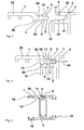
- FIG. 1 which represents a conventional construction bar forming a low sleeper crossbar
- the metal bars 502 and 522 are associated together through two insulating bars 501, in the same example.
- An insulating bar has two ends 503 and 523 respectively crimped into the metal bars 502 and 522.
- These ends 503 and 523 are, in the example, identical, and each constituted by a recessed triangular head whose base of the triangle constitutes the face d end of the insulating bar.
- Each recess housing 505, 525 in each metal bar 502, 522 for each triangular head of an insulating bar 501 is of substantially triangular cross-section, including a wall 511, 531, metal, or crimping metal head, accessible by means of crimping, is able to deform in order to exert a pressing force on one side of the triangular head.
- This pressure force has the effect of pressing the opposite side and the base of the triangular head against the corresponding bearing faces of the triangular groove of the metal bar constituting the housing of the triangular head of the insulating bar.
- a first disadvantage lies in the fact that the assembly of an insulating bar with a metal section, in particular by crimping, causes geometrical defects likely to modify the dimensioning of the bars of construction obtained, so as not to respect the tolerances of manufacturing.
- FIG. 1 shows the need to extend the metal crimping walls 611 and 631 towards the median plane of the construction bar, only to allow the action of the crimping tool, otherwise impeded by the grooves 637 and 638 of the seal located at ends of the metal profiles 622 and 602 respectively.
- a transverse end of an insulating section, nested in a metal section, has a longitudinal crimping head extended by a rib itself longitudinal; the crimping head of the insulating section is arranged to be machined by teeth formed in the metal section, when it is placed in force in the latter; the crimping head of the insulating profile forms a right angle with the plane of the insulating profile itself connecting the two metal profiles.
- Such an assembly technique requires a significant effort for the crimping operation.
- the first rib of the insulating bar adapted to be associated with the groove in the metal bar, combined with the profile having a form against undercut suitable for being associated with the housing, forms a new homogeneous and compact embedding head which confers the complete connection between the insulating bar and the metal bar, a great mechanical strength induced by the synergy of the shapes, and a better dimensional stability during the assembly of the bars, for example by crimping, and a fabrication facilitated by the compactness of the embedding head.
- the new embedding head of an insulating bar in a metal bar makes it possible to create new construction bars, some examples of embodiments of which will be described later.
- connection arrangement between the insulating bar and the metal bar makes it possible to crimp the construction bar according to the invention by means of a conventional crimping tool, for example a crimping wheel, without any additional effort.
- a conventional crimping tool for example a crimping wheel
- such an arrangement provides additional possibilities for bar constructions as will be further developed with the aid of exemplary embodiments.
- said first rib has a length of transverse extension beyond said undercut shape, substantially twice as large as its thickness.
- the construction bar according to the invention comprises a U-shape of which one of the two branches is formed by said insulating bar, the other of the two branches of the U being formed by said first metal bar.
- said first additional rib is formed on said first metal bar and said first additional groove is formed in said insulating bar, in a zone adjacent to said first end of the insulating bar.
- said at least one additional bearing surface of said first metal bar for the longitudinal support means of the insulating bar, located below said first profile having a form against undercut, is constituted by said first extra rib.
- said first rib has a length of transverse extension beyond said undercut shape, less than or equal to its thickness.
- the method according to the invention comprises a step of producing an insulating bar comprising a cellular section defining two connecting walls between said first bar and a second metal bar.
- said first rib has a length of transverse extension beyond said undercut shape, substantially twice as large as its thickness.
- said construction bar comprises a U-shape of which one of the two branches is formed by said insulating bar, the other of the two branches of the U being formed by said first metal bar.
- the first rib of the insulating bar is aligned or substantially aligned with the branch of the U formed by the insulating bar.
- said first additional rib is formed on said first metal bar and said first additional groove is formed in said insulating bar, in a zone adjacent to said first end of the insulating bar.
- said at least one additional bearing surface of said first metal bar for the longitudinal support means of the insulating bar, located below said first profile having a form against undercut, is constituted by said first extra rib.
- said first rib adopts a transverse extension length beyond said undercut shape, less than or equal to its thickness.
- the construction bar according to the invention comprises an insulating bar comprising a cellular section defining two connecting walls between said first metal bar and a second metal bar.
- FIGS. 1 and 2 are cross-sectional views of two building bars according to the prior art, respectively illustrating a lower cross member of sliding frame, and a sliding sash amount.
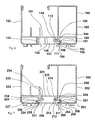
- FIG 3 is an enlarged cross-sectional view, before assembly, of a first exemplary embodiment of a construction bar (partial view) according to the invention and a first embodiment of an embodiment of an insulating bar.
- the figure 4 represents the examples bars, metallic (partial view) and insulating of the figure 3 , in an assembled position and crimped together.
- the figure 5 represents a view according to the figure 4 at normal scale, the metal bar being completely represented.
- the figure 6 represents a cross-sectional view, in an assembled but non-crimped position, of a second exemplary embodiment of a construction bar according to the invention and of a second exemplary embodiment of an insulating bar.
- the figure 7 represents a cross-sectional view, in assembled but unscrimped position, of a third exemplary embodiment of a construction bar according to the invention and a third embodiment of an embodiment of an insulating bar.
- the construction bar 10 shown on the Figures 3 to 5 comprises an insulating bar 1, of profiled type, adapted to be associated with a metal bar 2, of the profiled type, by a complete connection, having a cross section whose one end 3 is intended to be crimped to the metal bar 2.
- the first end 3 of the insulating bar 1 comprises a profile 4 with a form against undercut able to be engaged in a housing 5 of the metal bar.
- the cross section of the insulating bar 1 is extended, beyond the profile 4 having a shape against undercut, by a rib adapted to be disposed in a groove 7 of the metal bar 2.
- the rib 6 has a cross section complementary to the cross section of the groove 7, so as to form a connection of the insulating bar 1 and the metal bar 2, by embedding the undercut form and the rib respectively in the housing 5 and in the groove 7 of the metal bar 2.
- the first end 3 of the insulating bar 1 further comprises a longitudinal support means 50, located below the profile 4 having a form against undercut, adapted to come into contact with an additional bearing surface 12 of the metal bar 2, located below the housing 5 for the profile 4 with a shape against undercut.
- the rigid construction bar 10 obtained after assembly, by crimping as will be detailed below with an exemplary embodiment of a method of manufacturing the construction bar 10, the insulating bar 1 and the metal bar 2, as shown on the figure 5 is, in the example, a construction bar 10 whose cross-section adopts an H-shaped shape, one of the branches of the H being insulating, the other three, including the one 16 facing the insulating branch, being metallic, the central connecting branch being also metallic.
- This H-shape comprises, as shown in the drawings, a U-shaped shape defined by two of the branches of the H (insulating 15 and metal 16) for the two branches of the U, and by the transverse central branch of the H for the base of the A use of such a construction bar is, for example, after a cut to length, a sash amount.
- the outer shapes of the building bar 10 are shown by way of example in the figures and are otherwise known; they will not be described in more detail here.
- the connection zone between the insulating bar 1 and the metal bar, according to the invention, will now be described, according to the example of the Figures 3 to 5 .
- the form undercut advantageously adopts a triangular section 40 or substantially triangular
- the housing 5 of the metal bar 2 adopts a triangular section complementary to the triangular section of the insulating bar 1, as shown in FIG. figure 4
- the branch 39 of the insulating bar 1 forming the insulating branch 15 of the H of the construction bar 10 is attached to the triangular section 40 by the vertex of the triangle
- the rib 6 is attached to the base of the triangle 40, opposite to the vertex, advantageously extending perpendicularly to this base, in alignment or substantially in alignment with the branch 39 of the H, as shown in FIG. figure 3 .
- the rib 6 of the insulating bar 1 and the groove 7 of the metal bar 2 advantageously adopt respectively complementary sections with straight edges 8, 9 parallel.
- the cross section of the insulating bar 1 as represented on the figure 3 for example, is advantageously constant over the length of the bar, so that the embedding profile composed of the triangular shape against undercut and the right rib 6 is advantageously continuous over the length of the bar and thus the crimping.
- the rib 6 adopts a length of transverse extension beyond the form against undercut, ie a length taken between the base of the triangle 40 and the free end of the rib 6, substantially twice as large as the thickness of the rib 6.
- the thickness of the rib 6 is advantageously less than the base of the triangle 40 so that two bearing surfaces 41, 42 of the base of the triangular shape 40, on either side of the rib 6, can exert a pressing force against corresponding surfaces 43, 44 of reaction on the metal bar 2, during the crimping operation.
- the embedding end 3 of the insulating bar 1 is inserted in its corresponding recesses 5 and 7 made in the metal bar 2, by the longitudinal end of the bar and sliding from one to the other until alignment is achieved. respective ends of the bars.
- the crimping operation is then performed by deformation of the longitudinal wall 11 of the metal bar 2 forming the outer side of the triangular housing 5, as shown in FIGS. Figures 3 and 4 by means of a conventional crimping tool, for example by wheel.
- the figure 4 represents the wall 11 deformed after crimping.
- This wall advantageously comprises a pressure head in the form of a longitudinal edge which penetrates into the outer side of the triangular base of the insulating bar 1, as shown in FIG. figure 4 .
- first support force in the first direction 45 it is provided by the two faces 41 and 42 of the base of the triangle 40, on either side of the rib 6, pressing against the surfaces 43 and 44 corresponding, respectively, of the metal bar 2, which exerts a reaction to this first support force.
- the second support force in the second direction 46 it is provided by the longitudinal face 9 of the rib 6, opposite the side of the triangle 40 on which is exerted the crimping pressure, pressing against the surface 47 of the groove 7 of the metal bar, which exerts a reaction to this second support force.
- the crimping thanks to the embedding of the insulating bar 1 in the metal bar 2 as defined according to the invention, makes it possible to give the construction bar 10 a high mechanical strength.
- These supports are preferably provided along the length of bars 1 and 2.
- the crimping edge on the wall 11 exerts a force between the reaction of the groove 7 and the complementary bearing surface 12 opposite the wall 11, the complementary bearing surface 12 may for example be substantially aligned in the plane of the face 47 of the groove 7.
- the longitudinal bearing means 50 of the insulating bar may be, for example, as shown, constituted by a flat bearing surface which may preferably be aligned or substantially aligned with the longitudinal face 9 of the rib 6, but also parallel thereto.
- This additional bearing surface 12 may advantageously be formed on the metal bar 2, longitudinally, by a flat or substantially flat surface, directly in an area close to the housing 5, as shown in FIG. figure 4 .
- the insulating bar 1 will have a clearance 48 appropriate to allow the displacement of the wall 11 during crimping, as shown in the figure 4 .
- the construction bar 100 has a first 102 and a second 122 metal bars connected by an insulating bar 101 to a first 103 and a second 123 ends of the cross-section thereof, respectively.
- the metal bars 102 and 122 may each define any external appearance appropriate to the needs, and will not be described in more detail here. Only the connection interfaces with the insulating bar 101, according to the invention, will be detailed.
- the first transverse end 103 of the insulating bar is connected to the first metal bar 102 by a recess similar to that described in the first example, that is to say a recess comprising a profile 105 advantageously triangular against undercut, and a rib 106 in the extension of the profile 105.
- the metal bar 101 for example, advantageously comprises a first additional rib 113 associated with a first additional groove 114 formed in the insulating bar 101, the first additional rib 113 having a cross section complementary to the cross section of the first additional groove 114 so as to form a second connection of the insulating bar 101 and the first metal bar 102, by insertion or embedding of the first additional rib 113 in the first groove additional 114.
- the first additional rib 113 and the first additional groove 114 are formed in an area close to the first end 103 of the insulating bar 101, and preferably close to the profile 105 as shown in FIG. figure 6 .
- the first extra rib 113 and the first additional groove 114 are formed on the opposite side to the crimping wall 111 relative to the profile 105.
- the additional bearing surface 112 of the first metal bar 102 on the insulating bar 101 located below the first profile provided with of a form against undercut, is carried by the first additional rib 113, and more precisely defined by the face 112 of the rib 113 vis-à-vis the crimping wall 111, as shown in the figure 6 .
- the bearing surface complementary device 112 may for example be substantially aligned in the plane of the bearing face of the groove 107.
- the longitudinal support means 150 of the insulating bar 101 may be, for example, as shown, constituted by the flat surface of supporting the first additional groove 114, which may preferably be aligned or substantially aligned with the longitudinal face 109 of the rib 106, but also parallel thereto.
- the insulating bar 101 comprises for example a cellular section defining two walls 135, 136 connecting between the first 102 and second 122 metal bars, which is another difference with the first example.
- the connecting bar 101 thus has a first end 103 connecting these two walls 135 and 135, via a web perpendicular to the walls 135 and 136, in which are formed the groove 114 and the profile 105 against undercut provided with the extension rib 106, and a part of which may bear against the first metal bar.
- the ribs 106 and 113 are advantageously parallel so as to define parallel bearing faces during crimping.
- the rib 106 can be reduced to zero length, its effects then being replaced by those of the rib 113 associated with the groove 114.
- a such a configuration is less resistant than when the rib 106 is present and has for example, as shown, a length substantially equal to its thickness.
- the complete connection by crimping, according to the invention, between the first end 103 of the insulating bar 101 and the first metal profile 102 comprises a single crimping wall 111
- the complete connection by crimping, conventional, between the second end 123 of the insulating bar 101 and the second metal section 122 has two crimping walls, one for each conventional head.
- the connection according to the invention thus makes it possible to advantageously reduce the number of crimps to associate a cellular insulating bar with a metal bar, while obtaining a mechanical strength and a geometric dimensioning of the construction bar thus obtained, at least equal, and even superior in geometrical dimensioning due to the reduction of crimps and induced deformations.
- FIG. 7 A third example of building bar 200 and insulating bar 201 will now be described using the figure 7 .
- the third exemplary embodiment according to the figure 7 is different from the second example in that the second end 223 of the cross section of the insulating bar 201 is similar to the first end 203, and symmetrical thereto with respect to a median plane perpendicular to the walls 235 and 236 of the bar insulating 201.
- the construction bar according to the invention may comprise one or more aluminum-based profiles for example, and the insulating bar may be any insulating profile, in particular fiber-filled polyamide, or PVC.
- the insulating bar can adopt any external outline necessary for the needs of the construction bar.
- a primary application of the construction bar according to the invention is the metal joinery to provide thermal insulation, for frames, dormant, opening, fixed, frame, facade, etc ...
- An example of a manufacturing method of the construction bar 100 is very similar to that described above, with the exception of the structure of the insulating bar 101 and the two metal bars 102, 122, for which reference will be made to the descriptive part made above in support of the figure 6 .
- the insertion of the insulating bar 101 into the metal bars 102 and 122 can be done simultaneously or successively, longitudinally after the metal sections 102, 122 and the insulating section 101 have been placed end to end.
- the crimping of the three active parts, the part 111 is carried out in any known manner, with three knobs simultaneously, or with a wheel successively.
- An example of a method of manufacturing the bar 200 of construction is very similar to that described above for the manufacture of the bar 10, with the exception of the structure of the insulating bar 201 and the two metal bars 202, 222 , for which reference will be made to the descriptive part made above in support of the figure 7 .
- the insertion of the insulating bar 201 in the metal bars 202 and 222 can be done simultaneously or successively, longitudinally after the metal sections 202, 222 and the insulating section 201 have been put end to end.
- the crimping of the two active parts 211 and 231 is carried out in any known manner, with two wheels simultaneously, or with a wheel successively.
Landscapes
- Engineering & Computer Science (AREA)
- Civil Engineering (AREA)
- Structural Engineering (AREA)
- Manufacturing Of Electrical Connectors (AREA)
- Wing Frames And Configurations (AREA)
- Connector Housings Or Holding Contact Members (AREA)
Applications Claiming Priority (1)
| Application Number | Priority Date | Filing Date | Title |
|---|---|---|---|
| FR0707654A FR2922990B1 (fr) | 2007-10-31 | 2007-10-31 | Barre isolante, de type profile, destinee a etre associee a une barre metallique, de type profile, par une liaison complete, et barre de construction ainsi obtenue |
Publications (3)
| Publication Number | Publication Date |
|---|---|
| EP2055883A2 true EP2055883A2 (de) | 2009-05-06 |
| EP2055883A3 EP2055883A3 (de) | 2011-01-19 |
| EP2055883B1 EP2055883B1 (de) | 2013-12-18 |
Family
ID=39590727
Family Applications (1)
| Application Number | Title | Priority Date | Filing Date |
|---|---|---|---|
| EP08352022.1A Not-in-force EP2055883B1 (de) | 2007-10-31 | 2008-10-23 | Verfahren zur Herstellung einer Baustrebe durch Crimpen, und so erhaltene Baustrebe |
Country Status (2)
| Country | Link |
|---|---|
| EP (1) | EP2055883B1 (de) |
| FR (1) | FR2922990B1 (de) |
Cited By (2)
| Publication number | Priority date | Publication date | Assignee | Title |
|---|---|---|---|---|
| EP4390036A1 (de) * | 2022-12-22 | 2024-06-26 | Arconic Technologies LLC | Entwurf für thermische trennung |
| US20240209679A1 (en) * | 2022-12-22 | 2024-06-27 | Arconic Technologies Llc | Fenestration thermal break design |
Citations (1)
| Publication number | Priority date | Publication date | Assignee | Title |
|---|---|---|---|---|
| EP0235493A1 (de) | 1986-02-25 | 1987-09-09 | Geilinger AG | Wärmedämmendes Verbundprofil |
Family Cites Families (5)
| Publication number | Priority date | Publication date | Assignee | Title |
|---|---|---|---|---|
| DE7914521U1 (de) * | 1979-05-18 | 1979-10-25 | HEF Technische Entwicklung GmbH & Co KG, 4000 Düsseldorf | Anordnung zum verbinden zweier profilteile, insbesondere rahmenteile von metallfenstern |
| ES2076881B1 (es) * | 1993-12-02 | 1998-09-01 | Maricurreina Lorenzo Diaz | Sistema modular para la formacion de cerramientos acristalados. |
| FR2755995B1 (fr) * | 1996-11-15 | 1999-05-28 | Isapal Ingenierie Sarl | Chassis pour vantail coulissant dans un bati dormant a rainures |
| ATE310886T1 (de) * | 1998-03-13 | 2005-12-15 | All Co Spa | Zusammenbau aus strukturelementen, insbesondere ein profil und ein wärmeisolierendes element |
| FR2800791B1 (fr) * | 1999-11-05 | 2002-02-15 | Millet Et Cie | Menuiserie aluminium pour fenetre |
-
2007
- 2007-10-31 FR FR0707654A patent/FR2922990B1/fr not_active Expired - Fee Related
-
2008
- 2008-10-23 EP EP08352022.1A patent/EP2055883B1/de not_active Not-in-force
Patent Citations (1)
| Publication number | Priority date | Publication date | Assignee | Title |
|---|---|---|---|---|
| EP0235493A1 (de) | 1986-02-25 | 1987-09-09 | Geilinger AG | Wärmedämmendes Verbundprofil |
Cited By (3)
| Publication number | Priority date | Publication date | Assignee | Title |
|---|---|---|---|---|
| EP4390036A1 (de) * | 2022-12-22 | 2024-06-26 | Arconic Technologies LLC | Entwurf für thermische trennung |
| US20240209679A1 (en) * | 2022-12-22 | 2024-06-27 | Arconic Technologies Llc | Fenestration thermal break design |
| US12540502B2 (en) * | 2022-12-22 | 2026-02-03 | Arconic Technologies Llc | Fenestration thermal break design |
Also Published As
| Publication number | Publication date |
|---|---|
| FR2922990B1 (fr) | 2013-03-29 |
| EP2055883B1 (de) | 2013-12-18 |
| EP2055883A3 (de) | 2011-01-19 |
| FR2922990A1 (fr) | 2009-05-01 |
Similar Documents
| Publication | Publication Date | Title |
|---|---|---|
| CA2628810A1 (fr) | Procede de montage de lames sur une structure de support et organe de fixation ameliore | |
| EP3494315A1 (de) | Klammer zum zusammenhalten zweier flächiger teile | |
| FR2714686A1 (fr) | Revêtement de façade. | |
| EP2055883B1 (de) | Verfahren zur Herstellung einer Baustrebe durch Crimpen, und so erhaltene Baustrebe | |
| EP0186217B1 (de) | Rahmen | |
| EP1956173B1 (de) | Rahmen einer Schiebetür oder eines Schiebefensters, der einen verdeckten hohen Querriegel, Typ Monoblock, umfasst | |
| FR2594905A1 (fr) | Piece de jonction permettant d'assembler par rapprochement deux profiles tubulaires coupes a un angle donne | |
| WO2000050183A1 (fr) | Bague a retreindre et son procede de fabrication | |
| FR2802611A1 (fr) | Procede pour l'assemblage de profiles mixtes pour la realisation de chassis de porte ou fenetre | |
| EP0421836B1 (de) | Verfahren zur Herstellung eines Verbundprofils aus Holz und Metall und danach hergestelltes Profil | |
| FR3012839A1 (fr) | Raccord d'angle pour assembler des profiles creux, coupes en onglet, d'un chassis de porte ou de fenetre | |
| EP0142413B1 (de) | Mechanisches Mittel zum Zusammenbauen und Verstärken von Profilen und Verfahren zum Zusammenbauen von Profilen | |
| FR2702014A1 (fr) | Joint d'assemblage d'angle en onglet. | |
| EP1251233B1 (de) | Fensterrahmen mit einer metallischen Rahmenprofilanordnung | |
| EP1251230B1 (de) | Verfahren zum Verzieren eines Tür- oder Fensterbauteils aus Metall | |
| EP2317061B1 (de) | Pfosten für Türrahmen eines Gebäudes | |
| BE1020073A3 (fr) | Accessoire de finition tel que notamment un nez de marche ou une tablette, et son procede de fabrication. | |
| EP3043003B1 (de) | Pfette für die erstellung eines plattenrahmens für blindwand, die volle zonen umfasst, die die verstärkungszonen darstellen | |
| FR3007785A1 (fr) | Chassis dormant pour ouverture de batiment | |
| EP2226442B1 (de) | Profilzusammenbau vom Typ starre Kopplung | |
| EP0712975A1 (de) | Vorrichtung zum Zusammenbau und zur Befestigung von Verkleidungsplatten | |
| CH642525A5 (fr) | Procede de fabrication de meubles a assemblage par profiles et meuble obtenu. | |
| FR2847935A1 (fr) | Element de construction pour cadres en charpente, encadrement, menuiserie et notamment de portes et fenetres | |
| EP0072333A1 (de) | Verfahren zur Herstellung von vollen und steifen Wandelementen | |
| FR3125842A1 (fr) | Ensemble de menuiserie comportant un profile structural et un profile d’habillage |
Legal Events
| Date | Code | Title | Description |
|---|---|---|---|
| PUAI | Public reference made under article 153(3) epc to a published international application that has entered the european phase |
Free format text: ORIGINAL CODE: 0009012 |
|
| AK | Designated contracting states |
Kind code of ref document: A2 Designated state(s): AT BE BG CH CY CZ DE DK EE ES FI FR GB GR HR HU IE IS IT LI LT LU LV MC MT NL NO PL PT RO SE SI SK TR |
|
| AX | Request for extension of the european patent |
Extension state: AL BA MK RS |
|
| PUAL | Search report despatched |
Free format text: ORIGINAL CODE: 0009013 |
|
| AK | Designated contracting states |
Kind code of ref document: A3 Designated state(s): AT BE BG CH CY CZ DE DK EE ES FI FR GB GR HR HU IE IS IT LI LT LU LV MC MT NL NO PL PT RO SE SI SK TR |
|
| AX | Request for extension of the european patent |
Extension state: AL BA MK RS |
|
| RIC1 | Information provided on ipc code assigned before grant |
Ipc: E06B 3/273 20060101AFI20090105BHEP Ipc: E06B 3/263 20060101ALI20101215BHEP |
|
| 17P | Request for examination filed |
Effective date: 20110708 |
|
| AKX | Designation fees paid |
Designated state(s): AT BE BG CH CY LI |
|
| REG | Reference to a national code |
Ref country code: DE Ref legal event code: R108 Ref document number: 602008029372 Country of ref document: DE Effective date: 20110921 |
|
| RBV | Designated contracting states (corrected) |
Designated state(s): AT BE BG CH CY CZ DE DK EE ES FI FR GB GR HR HU IE IS IT LI LT LU LV MC MT NL NO PL PT RO SE SI SK TR |
|
| GRAP | Despatch of communication of intention to grant a patent |
Free format text: ORIGINAL CODE: EPIDOSNIGR1 |
|
| GRAS | Grant fee paid |
Free format text: ORIGINAL CODE: EPIDOSNIGR3 |
|
| GRAP | Despatch of communication of intention to grant a patent |
Free format text: ORIGINAL CODE: EPIDOSNIGR1 |
|
| INTG | Intention to grant announced |
Effective date: 20130709 |
|
| GRAA | (expected) grant |
Free format text: ORIGINAL CODE: 0009210 |
|
| AK | Designated contracting states |
Kind code of ref document: B1 Designated state(s): AT BE BG CH CY CZ DE DK EE ES FI FR GB GR HR HU IE IS IT LI LT LU LV MC MT NL NO PL PT RO SE SI SK TR |
|
| REG | Reference to a national code |
Ref country code: GB Ref legal event code: FG4D Free format text: NOT ENGLISH |
|
| REG | Reference to a national code |
Ref country code: CH Ref legal event code: EP |
|
| REG | Reference to a national code |
Ref country code: AT Ref legal event code: REF Ref document number: 645742 Country of ref document: AT Kind code of ref document: T Effective date: 20140115 |
|
| REG | Reference to a national code |
Ref country code: IE Ref legal event code: FG4D Free format text: LANGUAGE OF EP DOCUMENT: FRENCH |
|
| REG | Reference to a national code |
Ref country code: DE Ref legal event code: R096 Ref document number: 602008029372 Country of ref document: DE Effective date: 20140213 |
|
| REG | Reference to a national code |
Ref country code: NL Ref legal event code: VDEP Effective date: 20131218 |
|
| PG25 | Lapsed in a contracting state [announced via postgrant information from national office to epo] |
Ref country code: FI Free format text: LAPSE BECAUSE OF FAILURE TO SUBMIT A TRANSLATION OF THE DESCRIPTION OR TO PAY THE FEE WITHIN THE PRESCRIBED TIME-LIMIT Effective date: 20131218 Ref country code: NO Free format text: LAPSE BECAUSE OF FAILURE TO SUBMIT A TRANSLATION OF THE DESCRIPTION OR TO PAY THE FEE WITHIN THE PRESCRIBED TIME-LIMIT Effective date: 20140318 Ref country code: HR Free format text: LAPSE BECAUSE OF FAILURE TO SUBMIT A TRANSLATION OF THE DESCRIPTION OR TO PAY THE FEE WITHIN THE PRESCRIBED TIME-LIMIT Effective date: 20131218 Ref country code: SE Free format text: LAPSE BECAUSE OF FAILURE TO SUBMIT A TRANSLATION OF THE DESCRIPTION OR TO PAY THE FEE WITHIN THE PRESCRIBED TIME-LIMIT Effective date: 20131218 Ref country code: LT Free format text: LAPSE BECAUSE OF FAILURE TO SUBMIT A TRANSLATION OF THE DESCRIPTION OR TO PAY THE FEE WITHIN THE PRESCRIBED TIME-LIMIT Effective date: 20131218 |
|
| REG | Reference to a national code |
Ref country code: AT Ref legal event code: MK05 Ref document number: 645742 Country of ref document: AT Kind code of ref document: T Effective date: 20131218 |
|
| REG | Reference to a national code |
Ref country code: LT Ref legal event code: MG4D |
|
| PG25 | Lapsed in a contracting state [announced via postgrant information from national office to epo] |
Ref country code: LV Free format text: LAPSE BECAUSE OF FAILURE TO SUBMIT A TRANSLATION OF THE DESCRIPTION OR TO PAY THE FEE WITHIN THE PRESCRIBED TIME-LIMIT Effective date: 20131218 |
|
| PG25 | Lapsed in a contracting state [announced via postgrant information from national office to epo] |
Ref country code: IS Free format text: LAPSE BECAUSE OF FAILURE TO SUBMIT A TRANSLATION OF THE DESCRIPTION OR TO PAY THE FEE WITHIN THE PRESCRIBED TIME-LIMIT Effective date: 20140418 Ref country code: EE Free format text: LAPSE BECAUSE OF FAILURE TO SUBMIT A TRANSLATION OF THE DESCRIPTION OR TO PAY THE FEE WITHIN THE PRESCRIBED TIME-LIMIT Effective date: 20131218 |
|
| PG25 | Lapsed in a contracting state [announced via postgrant information from national office to epo] |
Ref country code: PL Free format text: LAPSE BECAUSE OF FAILURE TO SUBMIT A TRANSLATION OF THE DESCRIPTION OR TO PAY THE FEE WITHIN THE PRESCRIBED TIME-LIMIT Effective date: 20131218 Ref country code: RO Free format text: LAPSE BECAUSE OF FAILURE TO SUBMIT A TRANSLATION OF THE DESCRIPTION OR TO PAY THE FEE WITHIN THE PRESCRIBED TIME-LIMIT Effective date: 20131218 Ref country code: PT Free format text: LAPSE BECAUSE OF FAILURE TO SUBMIT A TRANSLATION OF THE DESCRIPTION OR TO PAY THE FEE WITHIN THE PRESCRIBED TIME-LIMIT Effective date: 20140418 Ref country code: NL Free format text: LAPSE BECAUSE OF FAILURE TO SUBMIT A TRANSLATION OF THE DESCRIPTION OR TO PAY THE FEE WITHIN THE PRESCRIBED TIME-LIMIT Effective date: 20131218 Ref country code: ES Free format text: LAPSE BECAUSE OF FAILURE TO SUBMIT A TRANSLATION OF THE DESCRIPTION OR TO PAY THE FEE WITHIN THE PRESCRIBED TIME-LIMIT Effective date: 20131218 Ref country code: CZ Free format text: LAPSE BECAUSE OF FAILURE TO SUBMIT A TRANSLATION OF THE DESCRIPTION OR TO PAY THE FEE WITHIN THE PRESCRIBED TIME-LIMIT Effective date: 20131218 Ref country code: AT Free format text: LAPSE BECAUSE OF FAILURE TO SUBMIT A TRANSLATION OF THE DESCRIPTION OR TO PAY THE FEE WITHIN THE PRESCRIBED TIME-LIMIT Effective date: 20131218 Ref country code: SK Free format text: LAPSE BECAUSE OF FAILURE TO SUBMIT A TRANSLATION OF THE DESCRIPTION OR TO PAY THE FEE WITHIN THE PRESCRIBED TIME-LIMIT Effective date: 20131218 Ref country code: CY Free format text: LAPSE BECAUSE OF FAILURE TO SUBMIT A TRANSLATION OF THE DESCRIPTION OR TO PAY THE FEE WITHIN THE PRESCRIBED TIME-LIMIT Effective date: 20131218 |
|
| REG | Reference to a national code |
Ref country code: DE Ref legal event code: R097 Ref document number: 602008029372 Country of ref document: DE |
|
| PLBE | No opposition filed within time limit |
Free format text: ORIGINAL CODE: 0009261 |
|
| STAA | Information on the status of an ep patent application or granted ep patent |
Free format text: STATUS: NO OPPOSITION FILED WITHIN TIME LIMIT |
|
| PG25 | Lapsed in a contracting state [announced via postgrant information from national office to epo] |
Ref country code: DK Free format text: LAPSE BECAUSE OF FAILURE TO SUBMIT A TRANSLATION OF THE DESCRIPTION OR TO PAY THE FEE WITHIN THE PRESCRIBED TIME-LIMIT Effective date: 20131218 |
|
| 26N | No opposition filed |
Effective date: 20140919 |
|
| REG | Reference to a national code |
Ref country code: DE Ref legal event code: R097 Ref document number: 602008029372 Country of ref document: DE Effective date: 20140919 |
|
| REG | Reference to a national code |
Ref country code: DE Ref legal event code: R119 Ref document number: 602008029372 Country of ref document: DE |
|
| PG25 | Lapsed in a contracting state [announced via postgrant information from national office to epo] |
Ref country code: SI Free format text: LAPSE BECAUSE OF FAILURE TO SUBMIT A TRANSLATION OF THE DESCRIPTION OR TO PAY THE FEE WITHIN THE PRESCRIBED TIME-LIMIT Effective date: 20131218 Ref country code: MC Free format text: LAPSE BECAUSE OF FAILURE TO SUBMIT A TRANSLATION OF THE DESCRIPTION OR TO PAY THE FEE WITHIN THE PRESCRIBED TIME-LIMIT Effective date: 20131218 Ref country code: LU Free format text: LAPSE BECAUSE OF FAILURE TO SUBMIT A TRANSLATION OF THE DESCRIPTION OR TO PAY THE FEE WITHIN THE PRESCRIBED TIME-LIMIT Effective date: 20141023 |
|
| REG | Reference to a national code |
Ref country code: CH Ref legal event code: PL |
|
| GBPC | Gb: european patent ceased through non-payment of renewal fee |
Effective date: 20141023 |
|
| PG25 | Lapsed in a contracting state [announced via postgrant information from national office to epo] |
Ref country code: BE Free format text: LAPSE BECAUSE OF NON-PAYMENT OF DUE FEES Effective date: 20141031 |
|
| REG | Reference to a national code |
Ref country code: IE Ref legal event code: MM4A |
|
| PG25 | Lapsed in a contracting state [announced via postgrant information from national office to epo] |
Ref country code: DE Free format text: LAPSE BECAUSE OF NON-PAYMENT OF DUE FEES Effective date: 20150501 Ref country code: GB Free format text: LAPSE BECAUSE OF NON-PAYMENT OF DUE FEES Effective date: 20141023 Ref country code: CH Free format text: LAPSE BECAUSE OF NON-PAYMENT OF DUE FEES Effective date: 20141031 Ref country code: LI Free format text: LAPSE BECAUSE OF NON-PAYMENT OF DUE FEES Effective date: 20141031 |
|
| REG | Reference to a national code |
Ref country code: FR Ref legal event code: ST Effective date: 20150630 |
|
| PG25 | Lapsed in a contracting state [announced via postgrant information from national office to epo] |
Ref country code: FR Free format text: LAPSE BECAUSE OF NON-PAYMENT OF DUE FEES Effective date: 20141031 |
|
| PG25 | Lapsed in a contracting state [announced via postgrant information from national office to epo] |
Ref country code: IE Free format text: LAPSE BECAUSE OF NON-PAYMENT OF DUE FEES Effective date: 20141023 |
|
| PG25 | Lapsed in a contracting state [announced via postgrant information from national office to epo] |
Ref country code: BG Free format text: LAPSE BECAUSE OF FAILURE TO SUBMIT A TRANSLATION OF THE DESCRIPTION OR TO PAY THE FEE WITHIN THE PRESCRIBED TIME-LIMIT Effective date: 20131218 |
|
| PG25 | Lapsed in a contracting state [announced via postgrant information from national office to epo] |
Ref country code: GR Free format text: LAPSE BECAUSE OF FAILURE TO SUBMIT A TRANSLATION OF THE DESCRIPTION OR TO PAY THE FEE WITHIN THE PRESCRIBED TIME-LIMIT Effective date: 20140319 Ref country code: IT Free format text: LAPSE BECAUSE OF FAILURE TO SUBMIT A TRANSLATION OF THE DESCRIPTION OR TO PAY THE FEE WITHIN THE PRESCRIBED TIME-LIMIT Effective date: 20131218 |
|
| PG25 | Lapsed in a contracting state [announced via postgrant information from national office to epo] |
Ref country code: MT Free format text: LAPSE BECAUSE OF FAILURE TO SUBMIT A TRANSLATION OF THE DESCRIPTION OR TO PAY THE FEE WITHIN THE PRESCRIBED TIME-LIMIT Effective date: 20131218 Ref country code: TR Free format text: LAPSE BECAUSE OF FAILURE TO SUBMIT A TRANSLATION OF THE DESCRIPTION OR TO PAY THE FEE WITHIN THE PRESCRIBED TIME-LIMIT Effective date: 20131218 Ref country code: HU Free format text: LAPSE BECAUSE OF FAILURE TO SUBMIT A TRANSLATION OF THE DESCRIPTION OR TO PAY THE FEE WITHIN THE PRESCRIBED TIME-LIMIT; INVALID AB INITIO Effective date: 20081023 |