EP2055902A1 - Turbine de centrale thermique comprenant une aube mobile et un aube statorique - Google Patents
Turbine de centrale thermique comprenant une aube mobile et un aube statorique Download PDFInfo
- Publication number
- EP2055902A1 EP2055902A1 EP07021317A EP07021317A EP2055902A1 EP 2055902 A1 EP2055902 A1 EP 2055902A1 EP 07021317 A EP07021317 A EP 07021317A EP 07021317 A EP07021317 A EP 07021317A EP 2055902 A1 EP2055902 A1 EP 2055902A1
- Authority
- EP
- European Patent Office
- Prior art keywords
- bucket
- turbine
- edge
- respect
- protrusion
- Prior art date
- Legal status (The legal status is an assumption and is not a legal conclusion. Google has not performed a legal analysis and makes no representation as to the accuracy of the status listed.)
- Withdrawn
Links
Images


Classifications
-
- F—MECHANICAL ENGINEERING; LIGHTING; HEATING; WEAPONS; BLASTING
- F01—MACHINES OR ENGINES IN GENERAL; ENGINE PLANTS IN GENERAL; STEAM ENGINES
- F01D—NON-POSITIVE DISPLACEMENT MACHINES OR ENGINES, e.g. STEAM TURBINES
- F01D5/00—Blades; Blade-carrying members; Heating, heat-insulating, cooling or antivibration means on the blades or the members
- F01D5/12—Blades
- F01D5/22—Blade-to-blade connections, e.g. for damping vibrations
- F01D5/225—Blade-to-blade connections, e.g. for damping vibrations by shrouding
-
- F—MECHANICAL ENGINEERING; LIGHTING; HEATING; WEAPONS; BLASTING
- F01—MACHINES OR ENGINES IN GENERAL; ENGINE PLANTS IN GENERAL; STEAM ENGINES
- F01D—NON-POSITIVE DISPLACEMENT MACHINES OR ENGINES, e.g. STEAM TURBINES
- F01D11/00—Preventing or minimising internal leakage of working-fluid, e.g. between stages
- F01D11/08—Preventing or minimising internal leakage of working-fluid, e.g. between stages for sealing space between rotor blade tips and stator
-
- F—MECHANICAL ENGINEERING; LIGHTING; HEATING; WEAPONS; BLASTING
- F05—INDEXING SCHEMES RELATING TO ENGINES OR PUMPS IN VARIOUS SUBCLASSES OF CLASSES F01-F04
- F05B—INDEXING SCHEME RELATING TO WIND, SPRING, WEIGHT, INERTIA OR LIKE MOTORS, TO MACHINES OR ENGINES FOR LIQUIDS COVERED BY SUBCLASSES F03B, F03D AND F03G
- F05B2240/00—Components
- F05B2240/20—Rotors
- F05B2240/33—Shrouds which are part of or which are rotating with the rotor
Definitions
- This invention relates to a turbine for a thermal power plant, e.g. a gas turbine or a steam turbine, comprising a rotor shaft having a rotational axis, a rotor bucket and a guide bucket, wherein each bucket is mounted in the turbine and comprises a respective blade section providing a working surface for a propulsion fluid powering the turbine, each of the blade sections comprises an edge extending radially with respect to the rotational axis, the edges being separated from each other by a gap between the respective blade sections, which gap has a given axial extension, and a first one of said buckets comprises a shroud, which is arranged on a radial end portion of its blade section and is configured for delimiting the flow of the propulsion fluid in a radial direction.
- a turbine for a thermal power plant e.g. a gas turbine or a steam turbine
- each bucket is mounted in the turbine and comprises a respective blade section providing a working surface for a propulsion fluid powering the turbine
- the present invention relates to a guide bucket for a turbine of a thermal power plant comprising a foot section and a blade section, wherein the foot section is configured for mounting the guide bucket to a housing of the turbine surrounding a rotor shaft of the turbine having a rotational axis, the blade section provides a working surface for a propulsion fluid powering the turbine and comprises an edge extending radially with respect to the rotational axis, and the foot section has an exposed portion, which is exposed to the propulsion fluid during the operation of the turbine.
- a propulsion fluid or working fluid is expected to follow a predefined path, the so-called flow-path within the main flow channel of the turbine.
- the propulsion fluid alternately passes stationary rings of guide buckets and rings of rotor buckets, which rotor buckets are mounted on a rotor shaft of the turbine.
- the propulsion fluid interacts with the blade sections of the buckets and thereby rotates the rotor buckets to propel the rotor shaft.
- the rotor shaft typically is connected to a generator, which converts the mechanical energy of the rotor shaft into electrical energy.
- the rotating components like the rotor shaft and the rotor buckets, are sealed against stationary components, like the housing and the guide buckets. The sealing is required to prohibit the propulsion fluid to bypass the blade sections of the turbine buckets.
- the sealing technology typically used is configured such that under all possible boundary conditions of operation contact between the rotating components and the stationary components is avoided to protect the turbine from mechanical damage. Due to comparatively large axial and radial movements of the stationary components and the rotating components relative to one another during operation of the turbine the sealing designs usually are of the so-called non-contacting sealing type. In this sealing type there is no sealing device contacting both components. Instead, residual axial and radial clearances are remaining.
- a turbine of the afore mentioned kind in which the shroud has a protrusion protruding with respect to the edge of the first bucket by a distance of at least 10% of the given axial extension of the gap.
- the first bucket can be the rotor bucket or the guide bucket of the turbine.
- the guide bucket and the rotor bucket are arranged at different locations along the rotational axis of the rotor shaft such that there is a gap between them, which gap has a given axial extension.
- the rotor bucket is mounted in a turbine by moving the rotor bucket in an axial direction from an assembly position into a mounted position.
- the gap referred to above is the gap between the respective blade sections in the mounted position of the rotor bucket.
- the given axial extension is preferably determined in the area of a radially outer end of the blade sections.
- the rotor bucket can be rotated into a position, in which the edge of its blade section facing towards the guide bucket is arranged directly opposite of the neighbouring edge of the guide bucket. In this arrangement the distance between the two neighbouring edges corresponds to the axial extension of the gap.
- a shroud arranged on a radially outer end of the blade section of the rotor bucket and typically used for connecting several rotor buckets to each other has a protrusion.
- This protrusion protrudes with respect to the afore mentioned edge of the rotor bucket by a distance of at least 10% of the given axial extension of the gap. Therefore, the protrusion protrudes towards the guide bucket, advantageously towards a foot section of the guide bucket.
- the inventive protrusion influences the fluid flow of propulsion fluid entering into a non-contacting seal between the shroud and a housing of the turbine or a non-contacting seal between the shroud and the rotor shaft in case of said protrusion being on a shroud of said guide bucket.
- the non-contacting seal comprises a so-called sealing cavity extending in a radial direction with respect to the rotational axis between the shroud e.g. and the housing of the turbine.
- the portion of the propulsion fluid diverted off the main fluid flow and headed for entering into the sealing cavity is referred to as leakage fluid.
- the leakage fluid is diverted off the main flow of propulsion fluid flowing in the direction of the rotational axis in a main flow channel of the turbine, in which the blade sections of the buckets are arranged.
- a turbine for a thermal power plant comprising a rotor shaft having a rotational axis, and a bucket, which bucket comprises a foot section and a blade section, wherein the blade section provides a working surface for a propulsion fluid powering the turbine and comprises an edge extending radially with respect to the rotational axis, and the foot section has an exposed portion, which is during the operation of the turbine exposed to the propulsion fluid, wherein the exposed portion of the foot section has a recess being recessed with respect to the edge of the guide bucket.
- the bucket can be a guide bucket or a rotor bucket.
- the above object is achieved according to the present invention by providing a guide bucket of the afore mentioned kind in which the exposed portion of the foot section has a recess being recessed with respect to the edge of the guide bucket.
- the foot section is used for mounting the guide bucket to the housing of the turbine.
- a main portion of the foot section also referred to as inserted portion, is generally inserted into the housing and therewith not exposed to the propulsion fluid.
- a generally smaller portion of the foot section adjacent to the blade section sticks out of the housing and is exposed to the propulsion fluid, mostly the leakage fluid, during the operation of the turbine.
- the exposed portion of the foot section has a recess or a depression being recessed with respect to the respective edge of the bucket.
- the depression therefore receeds behind a line formed by an extension of the edge of the bucket into the area of the foot section.
- the inventive recess in the exposed portion of the foot section influences the fluid dynamics of the propulsion fluid entering into a sealing cavity forming a non-contacting seal, e.g. between a shroud of a rotor bucket arranged next to the guide bucket and a housing of the turbine. This fluid is referred to as leakage fluid.
- the recess has the effect that the leakage fluid diverted from the main stream of propulsion fluid in the turbine gets oriented in a direction in which it can pass into the sealing cavity without additional turning or turbulences. Therefore, mixing effects between the leakage fluid and the propulsion fluid in the main flow channel of the turbine are reduced. Therefore, possible losses in the momentum of the propulsion fluid in the main flow channel are reduced and the power output of the turbine is improved.
- the before mentioned inventive turbine having a protrusion in the shroud of the first bucket comprises an other bucket, like a guide bucket, having the recess described before.
- the protrusion and the recess in combination have the effect to minimize the mixing effect between the leakage fluid flow and the main fluid to a particularly large extent. A possible vortex developing in the leakage fluid before entering the sealing cavity can thus be minimized in its extent or prevented completely.
- the provision of the recess in the other bucket reduces the risk of damaging the protrusion of the first bucket during assembly of the turbine. During assembly of the turbine the rotor bucket is axially shifted towards the guide bucket.
- the protrusion protrudes with respect to the edge of the rotor bucket by a distance of at least 20%, preferably at least 30% of the given axial extension of the gap.
- the protrusion protrudes by a distance of about 50% of the given axial extension of the gap.
- the guide bucket comprises a foot section, which is mounted to a housing of the turbine
- the turbine comprises an inlet cavity extending in an axial direction between the shroud and the foot section and being configured for accepting a flow of leakage fluid from the propulsion fluid, which leakage fluid is ducted through a non-contacting seal between the shroud and the housing or the rotor shaft, depending on the type of the other bucket, wherein the protrusion extends into the inlet cavity.
- the flow path of the propulsion fluid diverted from the main flow channel also referred to as leakage fluid passes through a well defined area of the inlet cavity and is therewith guided such that an interaction with the propulsion fluid in the main flow channel is prevented to a large extent.
- protrusion protrudes in an axial direction of the rotor shaft of the turbine towards the other one of the buckets, in particular the guide bucket, in particular towards a foot section of the other bucket. This way, the leakage fluid diverted from the main fluid flow for entering into the sealing cavity is prevented from interacting with the fluid in the main flow channel in a particularly effective manner.
- the turbine is configured for being powered with the propulsion fluid flowing in a given flow direction along the longitudinal axis, and if the edge of the first bucket, in particular the rotor bucket, is an upstream edge facing opposite to the flow direction.
- the protrusion is protruding with respect to the upstream edge of the rotor bucket in a direction opposite to the flow direction.
- the protrusion protrudes with respect to the edge of the first bucket, in particular the rotor bucket, by a distance of at least 5%, preferably 15% of an extension of the shroud in the axial direction.
- Such a protrusion reduces the amount of leakage fluid entering the sealing cavity as well as mixing effects between the diverted leakage fluid and the main fluid flow.
- the protrusion is tapered in a direction facing away from the edge of the first bucket, in particular the rotor bucket.
- the extension of the protrusion in a radial direction of the turbine is reduced in a direction facing away from the edge of the first bucket. The taper in the protrusion improves the guidance of the leakage fluid diverted from the main fluid flow and detrimental turbulences in the propulsion fluid are suppressed even more.
- the protrusion has a surface, which is tilted with respect to the longitudinal axis of the rotor shaft, in particular such that the surface includes an obtuse angle with the edge of the first bucket.
- the protrusion has a flat surface, which faces in an axial direction and extends parallel to the edge of the first bucket.
- the flat surface in particular extends perpendicular to the rotational axis. It faces upstream with regards to the flow direction of the propulsion fluid in the main flow channel.
- the shroud comprises a sealing surface, which faces in a radial direction and is configuard to form a non-contacting seal with a housing of the turbine or the rotor shaft, depending on the type of the first bucket, wherein the sealing surface has a stepped profile and/or at least one recess.
- the turbine is configured for being powered with the propulsion fluid flowing in a given flow direction in the main flow channel along the rotational axis and the edge of the other bucket, in particular the guide bucket is a downstream edge facing in the flow direction of the propulsion fluid.
- the recess in the foot section is recessed with respect to the edge in a direction opposite to the flow direction.
- the leakage fluid diverted from the main fluid flow is therefore essentially redirected twice before entering the sealing cavity. This reduces the amount of leakage fluid being diverted as well as possible mixing effects between the leakage fluid and the fluid in the main flow channel.
- the protrusion of the shroud of the other bucket, in particular the rotor bucket faces towards the recess in the foot section of the neighbouring bucket. This way, between the recess and the protrusion a defined channel for guiding the diverted leakage fluid is formed. Mixing effects between the diverted leakage fluid and the fluid in the main flow channel can thereby be reduced to a large extent.
- the recess is recessed with respect to the edge of the first bucket, in particular the guide bucket by a distance of at least 10%, preferably at least 30% of the given axial extension of the gap.
- the protrusion of the shroud protrudes with respect to the edge of the first bucket, in particular the rotor bucket, by at least the distance, by which the recess is recessed with respect to the edge of the other bucket, in particular the guide bucket. That means the protrusions sticks out relative to the edge of the blade section of the first bucket to the same extent or more than the recess in the foot section of the other bucket receeds with respect to the edge of the other bucket. This way, the channel formed between the recess and the protrusion becomes relatively narrow, which reduces the amount of leakage fluid being diverted.
- the recess portion has a rounded shape, in particular a profile in the form of a segment of a circle. With such a shape the fluid is guided particularly smoothly along the recess and possible turbulences affecting the main fluid flow are avoided.
- Fig. 1 shows a portion of a turbine 10 in a first embodiment according to the invention.
- the turbine 10 comprises a rotor shaft 12 having a rotational axis 14.
- the turbine 10 further includes by a housing 16 surrounding the rotor shaft 12 at a radial distance therefrom. Between the rotor shaft 12 and the housing 16 a main flow channel 18 for ducting a propulsion fluid is provided.
- the propulsion fluid flows in a given flow direction 19 parallel to the rotational axis 14.
- the turbine 10 further contains a rotor bucket 20 and a guide bucket 22.
- the rotor bucket 20 is mounted via a foot section 24 to the rotor shaft 12.
- the rotor bucket 20 is a single rotor bucket 20 within a row of rotor buckets 20.
- the row of rotor buckets 20 contains a number of rotor buckets 20 arranged around the circumference of the rotor shaft 12 in a given axial position, wherein each rotor bucket 20 extends radially with respect to the rotor shaft 12. Such a row of rotor buckets 20 extends in a plane perpendicular to the rotational axis 14. Therefore, only one rotor bucket 20 is shown in the drawing of fig. 1 .
- a guide bucket 22 is arranged in an axially shifted position next to the rotor bucket 20 .
- the guide bucket 22 also comprises a foot section 34, which is mounted in the housing 16.
- the guide bucket 22 is also part of a row of guide buckets 22 arranged at the inside of circumference of the housing 16 at one axial position.
- Each guide bucket 22 extends radially with respect to the rotational axis 14.
- several rows of guide buckets 22 and rotor buckets 20 are arranged in an alternating sequence.
- the rotor bucket 20 further comprises a blade section 26 and a shroud 28.
- the shroud 28 is arranged on the radially outer end of the blade section 26.
- the shroud 28 connects this end 27 of the blade section 26 with ends 27 of other blade sections within the row of rotor buckets 20 and therefore extends circumferentially with respect to the rotor shaft 12.
- the guide bucket 22 comprises a blade section 36 and a shroud 38, which in this case is arranged at a radially inner end 37 of the blade section 36.
- the blade sections 26 and 36 of the rotor bucket 20 and the guide bucket 22 respectively each have an upstream edge 30 and 39, respectively, extending radially with respect to the rotational axis 14 and facing oppositely to the flow direction 19 of the propulsion fluid.
- each of the blade sections 26 and 36 have downstream edges 32 and 40, respectively, also extending radially and facing in the flow direction 19.
- the downstream edge 40 of the guide bucket 22 and the upstream edge 30 of the rotor bucket 20 are separated from each other by a gap 41.
- the gap 41 has an axial extension d being the distance between the respective edges 40 and 30 in the state, in which the rotor bucket 20 is arranged in the mounted position shown in fig. 1 .
- the shroud 28 of the rotor bucket 20 and the housing 16 are separated from each other by a so-called non-contacting seal. That means the shroud 28 and the housing 16 are separated by a sealing cavity 48.
- the portion of the propulsion fluid diverted into the sealing cavity 48 is subsequently referred to as leakage fluid.
- the leakage fluid splits off the main fluid flow in an area between the foot section 34 of the guide bucket 22 and the shroud 28 of the rotor bucket 20. This area is referred to as inlet cavity 46. From the inlet cavity 46 the leakage fluid enters the sealing cavity 48, wherein a labyrinth-like duct structure is provided.
- the labyrinth-like duct structure is in part formed by a stepped profile of a sealing surface 50 of the shroud 28 facing towards the inside the sealing cavity 48.
- the shroud 28 has a protrusion 42 protruding with respect to the upstream edge 30 of the rotor bucket 20 in an axial direction of the rotor shaft 12 and facing towards the foot section 34 of the guide bucket 22.
- the protrusion 42 thereby extends about 50% of the axial extension d of the gap 41 with respect to the upstream edge 30.
- the protrusion 42 has a surface 43, which faces towards the rotor shaft 12 and is tilted with respect to the rotational axis 14 such that the distance between the surface 43 and the rotor shaft 12 narrows in the flow direction 19 of the propulsion fluid.
- the surface 43 therefore includes an obtuse angle ⁇ with the upstream edge 30 of the rotor bucket 20.
- the foot section 34 of the guide bucket 22 comprises an inserted portion 34, which is inserted into the housing 16 and is therefore not exposed to the propulsion fluid during operation. Further, the foot section 34 has an exposed portion 35, which sticks out of the housing 16 in a radially inward direction and is therefore exposed to the propulsion fluid during operation of the turbine 10.
- the exposed portion 35 has a recess 44, which is located on the downstream side of the foot section 34.
- the recess 44 is recessed with respect to the downstream edge 40 of the guide bucket 22 by a distance of about 30% of the axial extension d of the gap 41.
- the protrusion 42 faces towards the recess 44 and forms together with the recess 44 a channel for redirecting the leakage fluid after its diversion off the main fluid flow.
- the recess 44 has a profile in the form of a segment of a circle in a section along a longitudinal plane of the turbine 10, as shown in fig. 1 .
- the recess 44 therefore guides the leakage fluid together with the protrusion 42 smoothly into the sealing cavity 48.
- the provision of the recess 44 and the protrusion 42 prevents the formation of a vortex, which would cause some of the leakage fluid to re-enter the main flow channel 18 and therefore cause an undesired interaction of the leakage fluid with the main fluid flow slowing the momentum of the propulsion fluid in the main flow channel 18.
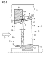
- fig. 2 depicts the portion of the turbine 10 shown in fig. 1 with the rotor bucket 20 being arranged in an assembly position. In this position the rotor bucket 20 is shifted in the axial direction toward the guide bucket 22. It can be seen from fig. 2 that the provision of the recess 44 reduces the risk of damaging the protrusion 42 during the assembly process as it provides a dent in the foot section 34 of the guide bucket 22 corresponding to the protrusion 42. At this point it is noted that depending on the operation of the turbine 10 the clearances between the guide bucket 22 and the rotor bucket 20 can also change in reverse when moving the rotor bucket 20 from the mounted position into the assembly position.
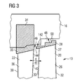
- Fig. 3 depicts a portion of a second embodiment of a turbine 10 according to the invention corresponding to the upper half of fig. 1 .
- Corresponding parts in the embodiments of figs. 1 and 2 are referred to with the same reference numerals.
- the embodiment according to fig. 3 differs from the embodiment according to fig. 1 only in the shape the protrusion 42, which in fig. 3 is referred to by reference numerous 142.
- the protrusion 142 has a flat surface 144, which faces in an axial direction with respect to the rotational axis 14 and extends parallel to the edge 30 of the rotor bucket 20.
- the foot section 34 in the embodiment according to fig. 3 differs from the foot section 34 in the embodiment according to fig. 1 in that no recess 44 is provided in the embodiment according to fig. 3 .
- Fig. 4 depicts a portion of a third embodiment of a turbine 10 according to the invention in an area around the rotor shaft 12. Parts corresponding to respective parts in the embodiments of fig. 1 and 2 are referred to with the same reference numbers wherever feasible.
- the embodiment according to fig. 4 differs form the embodiment according to fig. 1 in that the protrusion 42, which in the embodiment according to fig. 1 is part of the shroud 28 of the rotor bucket 20, according to fig. 4 is referred to as protrusion 242 and is part of the shroud 38 of the guide bucket 22.
- a recess 244 is contained in an exposed portion 225 of the foot section 24 of the rotor bucket 20.
- the recess is located on the side of the downstream edge 32 of the blade section 26 of the rotor bucket 20.
- the protrusion 242 is located on the side of the upstream edge 39 of the blade section 36 of the guide bucket 22.
- the upstream edge 39 and the downstream edge 32 are separated from each other by a gap 241.
- the gap 241 has an axial extension d' being the distance between the respective edges 39 and 32 in the state, in which the rotor bucket 20 is arranged in a mounted position.
- the protrusion 242 extends about 50 % of the axial extension d' of the gap 241 with respect to the upstream edge 39.
- the protrusion 242 has a surface 243, which faces away from the rotor shaft 12 and is tilted with respect to the rotational axis 14 such that the distance between the surface 243 and the rotor shaft widens in the flow direction 19 of the propulsion fluid.
- the surface 243 therefore includes an obtuse angle ⁇ with the upstream edge 39 of the guide bucket 22.
- the shroud 38 of the guide bucket 22 and the rotor shaft 12 are separated from each other by a so called non-contacting seal. That means, the shroud 38 and the rotor shaft 12 are separated by a sealing cavity 248.
- the portion of the propulsion fluid diverted into the sealing cavity 248 is referred to as leakage fluid.
- the leakage fluid splits off the main fluid flow in an area between the foot section 24 of the rotor bucket 20 and the shroud 38 of the guide bucket 22. This area is referred to as inlet cavity 246.
- the labyrinth - like duct structure is in part formed by a stepped profile of a sealing surface 250 of the shroud 38 facing towards the inside of the sealing cavity 248.
- a guide bucket 22 having a foot section 33 according to fig. 1 can be configured with a shroud 38 according to fig. 4 .
Landscapes
- Engineering & Computer Science (AREA)
- Mechanical Engineering (AREA)
- General Engineering & Computer Science (AREA)
- Turbine Rotor Nozzle Sealing (AREA)
Priority Applications (1)
| Application Number | Priority Date | Filing Date | Title |
|---|---|---|---|
| EP07021317A EP2055902A1 (fr) | 2007-10-31 | 2007-10-31 | Turbine de centrale thermique comprenant une aube mobile et un aube statorique |
Applications Claiming Priority (1)
| Application Number | Priority Date | Filing Date | Title |
|---|---|---|---|
| EP07021317A EP2055902A1 (fr) | 2007-10-31 | 2007-10-31 | Turbine de centrale thermique comprenant une aube mobile et un aube statorique |
Publications (1)
| Publication Number | Publication Date |
|---|---|
| EP2055902A1 true EP2055902A1 (fr) | 2009-05-06 |
Family
ID=39154084
Family Applications (1)
| Application Number | Title | Priority Date | Filing Date |
|---|---|---|---|
| EP07021317A Withdrawn EP2055902A1 (fr) | 2007-10-31 | 2007-10-31 | Turbine de centrale thermique comprenant une aube mobile et un aube statorique |
Country Status (1)
| Country | Link |
|---|---|
| EP (1) | EP2055902A1 (fr) |
Cited By (1)
| Publication number | Priority date | Publication date | Assignee | Title |
|---|---|---|---|---|
| DE102023212298A1 (de) | 2023-12-06 | 2025-06-12 | Siemens Energy Global GmbH & Co. KG | Anordnung für eine Strömungsmaschine |
Citations (12)
| Publication number | Priority date | Publication date | Assignee | Title |
|---|---|---|---|---|
| FR703653A (fr) * | 1929-10-18 | 1931-05-04 | Gen Electric | Perfectionnements aux turbines à fluide élastique |
| US2336323A (en) * | 1942-03-12 | 1943-12-07 | Gen Electric | Sealing arrangement for elastic fluid turbines and the like |
| DE2462465A1 (de) * | 1974-03-21 | 1977-04-28 | Maschf Augsburg Nuernberg Ag | Einrichtung zum dynamischen stabilisieren des laeufers eines verdichters |
| FR2384949A1 (fr) * | 1977-03-26 | 1978-10-20 | Rolls Royce | Dispositif d'etancheite pour rotor de turbine a gaz |
| JPS55146201A (en) * | 1979-05-04 | 1980-11-14 | Hitachi Ltd | Moving blade for turbine |
| JPS5728810A (en) * | 1980-07-28 | 1982-02-16 | Hitachi Ltd | Fluid turbine |
| EP1001139A1 (fr) * | 1998-11-10 | 2000-05-17 | Asea Brown Boveri AG | Dispositif d'étanchéité pour les extrémités des aubes de turbine |
| WO2001081731A1 (fr) * | 2000-04-20 | 2001-11-01 | Alstom (Switzerland) Ltd | Turbine a vapeur comportant un porte-aubes associe a un rotor et/ou un stator |
| US20040223844A1 (en) * | 2003-05-07 | 2004-11-11 | Farrell Alison Carol | Method and apparatus to facilitate sealing within turbines |
| EP1515000A1 (fr) * | 2003-09-09 | 2005-03-16 | ALSTOM Technology Ltd | Aubage d'une turbomachine avec un carenage contouré |
| FR2883920A1 (fr) * | 2005-04-01 | 2006-10-06 | Gen Electric | Distributeur de turbine avec angle adouci de la cavite de purge |
| EP1767746A1 (fr) * | 2005-09-22 | 2007-03-28 | Siemens Aktiengesellschaft | Aube statorique et aube de rotor d'une turbine et section de turbine comportant de telles aubes |
-
2007
- 2007-10-31 EP EP07021317A patent/EP2055902A1/fr not_active Withdrawn
Patent Citations (12)
| Publication number | Priority date | Publication date | Assignee | Title |
|---|---|---|---|---|
| FR703653A (fr) * | 1929-10-18 | 1931-05-04 | Gen Electric | Perfectionnements aux turbines à fluide élastique |
| US2336323A (en) * | 1942-03-12 | 1943-12-07 | Gen Electric | Sealing arrangement for elastic fluid turbines and the like |
| DE2462465A1 (de) * | 1974-03-21 | 1977-04-28 | Maschf Augsburg Nuernberg Ag | Einrichtung zum dynamischen stabilisieren des laeufers eines verdichters |
| FR2384949A1 (fr) * | 1977-03-26 | 1978-10-20 | Rolls Royce | Dispositif d'etancheite pour rotor de turbine a gaz |
| JPS55146201A (en) * | 1979-05-04 | 1980-11-14 | Hitachi Ltd | Moving blade for turbine |
| JPS5728810A (en) * | 1980-07-28 | 1982-02-16 | Hitachi Ltd | Fluid turbine |
| EP1001139A1 (fr) * | 1998-11-10 | 2000-05-17 | Asea Brown Boveri AG | Dispositif d'étanchéité pour les extrémités des aubes de turbine |
| WO2001081731A1 (fr) * | 2000-04-20 | 2001-11-01 | Alstom (Switzerland) Ltd | Turbine a vapeur comportant un porte-aubes associe a un rotor et/ou un stator |
| US20040223844A1 (en) * | 2003-05-07 | 2004-11-11 | Farrell Alison Carol | Method and apparatus to facilitate sealing within turbines |
| EP1515000A1 (fr) * | 2003-09-09 | 2005-03-16 | ALSTOM Technology Ltd | Aubage d'une turbomachine avec un carenage contouré |
| FR2883920A1 (fr) * | 2005-04-01 | 2006-10-06 | Gen Electric | Distributeur de turbine avec angle adouci de la cavite de purge |
| EP1767746A1 (fr) * | 2005-09-22 | 2007-03-28 | Siemens Aktiengesellschaft | Aube statorique et aube de rotor d'une turbine et section de turbine comportant de telles aubes |
Cited By (1)
| Publication number | Priority date | Publication date | Assignee | Title |
|---|---|---|---|---|
| DE102023212298A1 (de) | 2023-12-06 | 2025-06-12 | Siemens Energy Global GmbH & Co. KG | Anordnung für eine Strömungsmaschine |
Similar Documents
| Publication | Publication Date | Title |
|---|---|---|
| KR101536057B1 (ko) | 축류 터빈 | |
| JP6216643B2 (ja) | スワール阻止シールを有するターボ機械 | |
| US7971882B1 (en) | Labyrinth seal | |
| EP2039886B1 (fr) | Soupape de retenue composite | |
| KR101516102B1 (ko) | 축 시일 장치 및 이것을 구비하는 회전 기계 | |
| CN102200036A (zh) | 用于带护罩的燃气涡轮机叶片的主动顶隙控制和相关方法 | |
| US20110085892A1 (en) | Vortex chambers for clearance flow control | |
| CA2673079C (fr) | Turbo machine, en particulier turbine a gaz | |
| EP2894377B1 (fr) | Turbo-machine | |
| US20180171804A1 (en) | Turbine rotor blade arrangement for a gas turbine and method for the provision of sealing air in a turbine rotor blade arrangement | |
| EP3012409B1 (fr) | Ensemble de turbine | |
| KR102545920B1 (ko) | 터빈을 위한 팁 밸런스 슬릿 | |
| JP2017155859A (ja) | シール装置、回転機械 | |
| US9574453B2 (en) | Steam turbine and methods of assembling the same | |
| JP2004011553A (ja) | 軸流型ターボ機械 | |
| EP2055902A1 (fr) | Turbine de centrale thermique comprenant une aube mobile et un aube statorique | |
| US11066946B2 (en) | Axial turbomachinery | |
| EP2055896A1 (fr) | Aube dotée d'une pied pour turbine de centrale thermique | |
| EP2055901A1 (fr) | Aubage doté d'une section à pied pour turbine de centrale thermique | |
| JP7130575B2 (ja) | 軸流タービン | |
| JP5404187B2 (ja) | 端壁部材及びガスタービン | |
| JP2014199059A (ja) | 端壁部材及びガスタービン | |
| CN113374532B (zh) | 蒸汽轮机 | |
| JP2005214051A (ja) | 軸流タービン段落及び軸流タービン | |
| JP5852190B2 (ja) | 端壁部材及びガスタービン |
Legal Events
| Date | Code | Title | Description |
|---|---|---|---|
| PUAI | Public reference made under article 153(3) epc to a published international application that has entered the european phase |
Free format text: ORIGINAL CODE: 0009012 |
|
| AK | Designated contracting states |
Kind code of ref document: A1 Designated state(s): AT BE BG CH CY CZ DE DK EE ES FI FR GB GR HU IE IS IT LI LT LU LV MC MT NL PL PT RO SE SI SK TR |
|
| AX | Request for extension of the european patent |
Extension state: AL BA HR MK RS |
|
| AKX | Designation fees paid | ||
| STAA | Information on the status of an ep patent application or granted ep patent |
Free format text: STATUS: THE APPLICATION IS DEEMED TO BE WITHDRAWN |
|
| 18D | Application deemed to be withdrawn |
Effective date: 20091107 |
|
| REG | Reference to a national code |
Ref country code: DE Ref legal event code: 8566 |