EP2055914B1 - Mehrfachverbindungs-Motor mit variablem Verdichtungsverhältnis - Google Patents
Mehrfachverbindungs-Motor mit variablem Verdichtungsverhältnis Download PDFInfo
- Publication number
- EP2055914B1 EP2055914B1 EP08167313.9A EP08167313A EP2055914B1 EP 2055914 B1 EP2055914 B1 EP 2055914B1 EP 08167313 A EP08167313 A EP 08167313A EP 2055914 B1 EP2055914 B1 EP 2055914B1
- Authority
- EP
- European Patent Office
- Prior art keywords
- control shaft
- compression ratio
- link
- shaft
- control
- Prior art date
- Legal status (The legal status is an assumption and is not a legal conclusion. Google has not performed a legal analysis and makes no representation as to the accuracy of the status listed.)
- Ceased
Links
- 230000006835 compression Effects 0.000 title claims description 170
- 238000007906 compression Methods 0.000 title claims description 170
- 230000007246 mechanism Effects 0.000 claims description 61
- 230000009467 reduction Effects 0.000 claims description 56
- 230000008859 change Effects 0.000 claims description 7
- 230000008878 coupling Effects 0.000 claims description 2
- 238000010168 coupling process Methods 0.000 claims description 2
- 238000005859 coupling reaction Methods 0.000 claims description 2
- 238000010586 diagram Methods 0.000 description 11
- 238000005452 bending Methods 0.000 description 7
- 230000000694 effects Effects 0.000 description 5
- 230000007423 decrease Effects 0.000 description 3
- 239000000446 fuel Substances 0.000 description 3
- 230000001133 acceleration Effects 0.000 description 2
- 230000002146 bilateral effect Effects 0.000 description 2
- 238000002485 combustion reaction Methods 0.000 description 2
- 238000007796 conventional method Methods 0.000 description 2
- 230000003247 decreasing effect Effects 0.000 description 2
- 230000009471 action Effects 0.000 description 1
- 238000013459 approach Methods 0.000 description 1
- 230000000052 comparative effect Effects 0.000 description 1
- 230000009977 dual effect Effects 0.000 description 1
- 238000005516 engineering process Methods 0.000 description 1
- 238000012986 modification Methods 0.000 description 1
- 230000004048 modification Effects 0.000 description 1
- 230000004043 responsiveness Effects 0.000 description 1
Images



Classifications
-
- F—MECHANICAL ENGINEERING; LIGHTING; HEATING; WEAPONS; BLASTING
- F02—COMBUSTION ENGINES; HOT-GAS OR COMBUSTION-PRODUCT ENGINE PLANTS
- F02B—INTERNAL-COMBUSTION PISTON ENGINES; COMBUSTION ENGINES IN GENERAL
- F02B75/00—Other engines
- F02B75/04—Engines with variable distances between pistons at top dead-centre positions and cylinder heads
- F02B75/048—Engines with variable distances between pistons at top dead-centre positions and cylinder heads by means of a variable crank stroke length
Definitions
- the present invention generally relates to a multi-link variable compression ratio engine and particularly, but not exclusively, to a variable compression ratio mechanism for an engine which uses, non-exclusively, a control shaft, multiple links, a drive motor, and a reduction mechanism to change a top dead center position of a piston.
- aspects of the invention relate to an apparatus, to an engine and to a vehicle.
- a known example of a variable compression ratio mechanism of an engine is one in which a piston and a crank are connected via a plurality of links.
- the piston and the crank are connected via an upper link and a lower link, and the compression ratio is variably controlled by controlling the orientation of the lower link.
- the mechanism comprises a control link connected to an eccentric axle provided to a control shaft that is connected at one end to the lower link and extends substantially parallel to the crankshaft at the other end.
- the orientation of the lower link is controlled via the control link by varying the angle of rotation of the control shaft.
- the angle of rotation of the control shaft is controlled by a shaft control mechanism comprising a fork provided integrally to the control shaft, an actuator rod connected to the fork via a connecting pin, and a drive motor for causing the actuator rod to advance and retract in a direction orthogonal to the control shaft.
- connection mechanism using a fork such as in Patent Document 1 (hereinafter referred to as "fork-type connection mechanism") is configured so that the fork oscillates with bilateral symmetry in relation to the rotational axis of the control shaft, and the reduction ratio between the drive motor and the control shaft varies according to the advanced or retracted position of the actuator rod.
- the reduction ratio is large at a high compression ratio, the control shaft loses responsiveness when the compression ratio is changed from a high compression ratio to an intermediate compression ratio.
- Embodiments of the invention therefore provide an improved multi-link variable compression ratio engine in which it is possible to suppress the occurrence of knocking caused by changes in the compression ratio.
- an apparatus for an engine comprising a crankshaft, a cylinder and a piston operatively coupled to the crankshaft to move back and forth within the cylinder
- the apparatus comprising a control shaft rotatably supported on the engine, the control shaft having an eccentric axle that is eccentric relative to a rotational center axis of the control shaft, a linkage operatively connecting the piston to the crankshaft and the crankshaft to the eccentric axle of the control shaft, a drive motor operatively coupled to the control shaft to rotate the control shaft about the rotational center axis such that a top dead center position of the piston is changed so as to vary a compression ratio of the engine, and a reduction mechanism coupling the drive motor to the control shaft to reduce the rotation of the drive motor and transmit the rotation to the control shaft such that a reduction ratio of a rotation angle of the drive motor to a rotation angle of the control shaft is less at a high compression ratio than at an intermediate compression ratio.
- the reduction mechanism is configured such that the reduction ratio is less at a low compression ratio than at the intermediate compression ratio.
- the reduction mechanism further includes a threaded drive mechanism connecting the actuator rod to the drive motor by a screw structure to convert the rotational motion of the drive motor to the actuator rod for advancing and retracting the actuator rod.
- the reduction mechanism includes an elliptically shaped shaft-side pinion gear mounted on the control shaft to rotate integrally with the control shaft.
- the reduction mechanism may further comprise an elliptically shaped drive-side pinion gear meshed with the shaft-side pinion gear and turned by the drive motor.
- the drive motor may be arranged to turn the drive-side pinion gear in accordance with an operating state of the engine and turn the control shaft via the shaft-side pinion gear to vary the compression ratio of the engine.
- the linkage includes an upper link rotatably connected to the piston via a piston pin, a lower link rotatably mounted on a crank pin of the crankshaft and rotatably connected to the upper link via an upper pin and a control link rotatably connected at one end to the lower link via a control pin and rotatably connected at the other end to the eccentric axle of the control shaft.
- the reduction mechanism includes an intermediate control link connected to the control shaft at a position offset from the rotational center axis of the control shaft and a connecting link connected to the intermediate control link at one end of the connecting link and to the control shaft at another end of the connecting link.
- the intermediate control link, the connecting link, and the actuator rod may be arranged such that, at an intermediate compression ratio, a 180° angle is formed by the control shaft and the connecting link, a 90° angle is formed by the connecting link and the intermediate control link, and a 180° angle is formed by the intermediate control link and the actuator rod.
- a multi-link variable compression ratio engine may comprise a crankshaft, a piston, a control shaft, linkage, a drive motor, and a reduction mechanism.
- the piston is operatively coupled to the crankshaft to move back and forth within a cylinder of the engine.
- the control shaft is rotatably supported on the engine.
- the control shaft also has an eccentric axle that is eccentric relative to a rotational center axis of the control shaft.
- the linkage operatively connects the piston to the crankshaft and the crankshaft to the eccentric axle of the control shaft.
- the drive motor is operatively coupled to the control shaft to rotate the control shaft about the rotational center axis. This rotation causes a top dead center position of the piston to change by turning the control shaft.
- the reduction mechanism couples the drive motor to the control shaft to reduce the rotation of the drive motor and transmit the rotation to the control shaft. This transmitting of rotation causes a reduction ratio of a rotation angle of the drive motor to a rotation angle of the control shaft to be less at a high compression ratio than at an intermediate compression ratio, and to be less at a low compression ratio than at the intermediate compression ratio.
- a multi-link variable compression ratio engine 1 as seen from the direction of the crankshaft is illustrated in accordance with a first embodiment of the present invention.
- a multi-link variable compression ratio engine 1 comprises a compression ratio varying mechanism 10 for varying the top dead center position of a piston in order to vary the compression ratio.
- a piston 11 and a crankshaft 12 are connected by an upper link 13 and a lower link 14, and the compression ratio is varied by controlling the orientation of the lower link 14 with the aid of a control link 15.
- the upper link, the lower link, and the control link may be considered a linkage.
- the upper link 13 is connected to the piston 11 at the top end via a piston pin 13a.
- the bottom end of the upper link 13 is connected to one end of the lower link 14 via an upper pin 14a.
- the other end of the lower link 14 is connected to the control link 15 via a control pin 14b.
- the lower link 14 has a connecting hole 14c, and a crank pin 12a of the crankshaft 12 is inserted through the connecting hole 14c.
- the lower link 14 oscillates around the crank pin 12a which serves as a center axis for the lower link 14.
- the crankshaft 12 comprises the crank pin 12a, a journal 12b, and a counterweight 12c.
- the center of the crank pin 12a is eccentric relative to the center of the journal 12b by a predetermined amount.
- the counterweight 12c is formed integrally with a crank arm connecting the journal 12b to the crank pin 12a, reducing the rotational first-order vibration component of the piston movement.
- control link 15 The top end of the control link 15 is rotatably connected to the lower link 14 via the control pin 14b.
- the bottom end of the control link 15 is connected to a control shaft 20.
- the control shaft 20 is disposed substantially parallel to the crankshaft 12, and is supported in a rotatable manner on the engine body.
- the control shaft 20 comprises an eccentric axle 21 and a shaft-controlling axle 22.
- the eccentric axle 21 is eccentric relative to the rotational axis of the control shaft 20 by a predetermined amount.
- the control link 15 oscillates in relation to the eccentric axle 21.
- the shaft-controlling axle 22 is provided so that the center of the axle coincides with the rotational axis of the control shaft 20.
- a connecting link 31 of a shaft control mechanism 30 is fixed to the shaft-controlling axle 22, and the connecting link 31 thereby turns integrally with the control shaft 20.
- the connecting link 31 is a separate structure assembled on the control shaft 20, but the link may also be formed integrally with the control shaft 20.
- the control shaft of the claims can be understood to include the connecting link 31 of the shaft control mechanism 30 as well.
- the shaft control mechanism 30 comprises the connecting link 31, an intermediate control link 32, an actuator rod 33, a ball screw nut 34, and a drive motor 35.
- the shaft control mechanism 30 controls the angle of rotation of the control shaft 20.
- One end of the connecting link 31 is fixed to the shaft-controlling axle 22 so as to rotate integrally with the control shaft 20.
- the other end of the connecting link 31 is rotatably connected to one end of the intermediate control link 32 via a connecting pin 36.
- the other end of the intermediate control link 32 is rotatably connected to one end of the actuator rod 33 via a connecting pin 37.
- the actuator rod 33 has, in the outer periphery of the proximal end side (the right side in the drawing), a ball screw part 33a in which a male thread is formed.
- the ball screw part 33a is screwed into a female thread formed in the interior of the ball screw nut 34.
- the actuator rod 33 is provided to the ball screw nut 34 in a manner that allows the actuator rod to advance and retract.
- the actuator rod 33 moves back and forth relative to the ball screw nut 34.
- the drive motor 35 has a mechanism (hereinafter referred to as “holding mechanism”) for switching between permitting and halting the rotation of the control shaft 20 to hold the control shaft 20 at a predetermined angle of rotation.
- the combustion pressure in the cylinder, the inertial force of the piston 11, and the like are transmitted to the control shaft 20 via the upper link 13, the lower link 14, and the control link 15. These transmitted loads act as torque for turning the control shaft 20 (hereinafter referred to as “control shaft torque”), because the eccentric axle 21 is eccentric relative to the rotational axis of the control shaft 20.
- the drive motor 35 holds the control shaft 20 at a predetermined angle of rotation against the control shaft torque due to the flow of an electric current in the opposite direction from the control shaft torque during driving.
- the variable compression ratio engine 1 has a controller 40 configured to vary the compression ratio in accordance with the operating state of the engine.
- the controller 40 has a CPU, ROM, RAM and an I/O interface.
- the controller 40 controls the driving of the drive motor 35 of the shaft control mechanism 30 in order to vary the compression ratio in accordance with the operating state of the engine.
- variable compression ratio engine 1 configured as described above, the driving of the drive motor 35 is controlled by the controller 40, and the actuator rod 33 is made to advance and retract linearly in accordance with the operating state of the engine, whereby the angle of rotation of the control shaft 20 is controlled and the compression ratio is varied.
- the control shaft 20 turns counterclockwise in the drawing via the intermediate control link 32 and the connecting link 31 around the shaft-controlling axle 22 as a rotational axis when the actuator rod 33 of the shaft control mechanism 30 retracts toward the right side of the drawing in FIG. 1 .
- the position of the eccentric axle 21 to which the control link 15 is connected is thereupon lowered.
- the eccentric axle 21 is thus lowered, the lower link 14 tilts counterclockwise in the drawing around the crank pin 12a, raising the position of the upper pin 14a, and the top dead center position of the piston 11 therefore rises, increasing the compression ratio.
- the control shaft 20 turns clockwise in the drawing via the intermediate control link 32 and the connecting link 31 around the shaft-controlling axle 22 as a rotational axis when the actuator rod 33 advances to the left in the drawing.
- the position of the eccentric axle 21 thereupon rises, the lower link 14 tilts, and the position of the upper pin 14a is lowered, causing the top dead center position of the piston 11 to be lowered, decreasing the compression ratio.
- the rotation of the drive motor 35 causes the control shaft 20 to be turned by the back-and-forth movement of the actuator rod 33 accompanying the relative rotation between the ball screw nut 34 and the ball screw part 33a, and then by the resulting movement of the intermediate control link 32 and the connecting link 31.
- the rotational speed of the drive motor 35 is reduced by the arrangement of these links (hereinafter referred to as the "link geometry") and is converted to rotation of the control shaft 20.
- the link geometry changes and the control shaft 20 turns when there is a change in the advanced or retracted position of the actuator rod 33.
- the reduction ratio between the drive motor 35 and the control shaft 20 is equal to the angle of rotation of the drive motor 35 divided by the angle of rotation of the control shaft 20.
- the reduction ratio changes when there is such a change in the link geometry.
- a reduction mechanism is configured from the connecting link 31, the intermediate control link 32, the actuator rod 33, and the ball screw nut 34 in the shaft control mechanism 30.
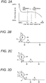
- FIG. 2A is a graph showing the relationship between the reduction ratio and the control shaft angle which depends on the link geometry.
- the horizontal axis represents the angle of rotation ⁇ cs of the control shaft 20 (hereinafter referred to as the "control shaft angle").
- the vertical axis represents the relationship in reduction ratios between the drive motor and the control shaft.
- the control shaft angle ⁇ cs is the angle of rotation from a predetermined position, and the angle is positive when the control shaft 20 turns counterclockwise in FIG. 1 .
- the reduction ratio changes as shown in FIG. 2A when there is a change in the link geometry which causes the control shaft 20 to turn. Particularly, the reduction ratio increases from ⁇ 1 to ⁇ 2, and the reduction ratio decreases from ⁇ 2 to ⁇ 3 when the control shaft angle ⁇ cs is in a range from ⁇ 1 to ⁇ 3.
- the control shaft angle ⁇ cs is varied to control the compression ratio of the variable compression ratio engine 1.
- the settings are designed so that when the control shaft angle ⁇ cs is ⁇ 1, the compression ratio is at the minimum level, and when the control shaft angle ⁇ cs is ⁇ 3, the compression ratio is at the maximum level.
- FIGS. 2B through 2D are diagrams, as seen from the axial direction of the control shaft, showing the angles of the link geometry between the connecting link 31, the intermediate control link 32, and the actuator rod 33 when the control shaft angle ⁇ cs is at ⁇ 1, ⁇ 2, or ⁇ 3 at various compression ratios.
- the angle ⁇ a formed by the connecting link 31 and the intermediate control link 32 is less than 90°, and the angle ⁇ b formed by the intermediate control link 32 and the actuator rod 33 is less than 180°, as shown in FIG. 2B .
- the angle ⁇ a formed by the connecting link 31 and the intermediate control link 32 is substantially 90°
- the angle ⁇ b formed by the intermediate control link 32 and the actuator rod 33 is substantially 180°, as shown in FIG. 2C .
- the angle ⁇ a formed by the connecting link 31 and the intermediate control link 32 is greater than 90°, and the angle ⁇ b formed by the intermediate control link 32 and the actuator rod 33 is less than 180°, as shown in FIG. 2D .
- a fork-type connection mechanism based on a conventional method is configured so that the fork oscillates in bilateral symmetry in relation to the rotational axis of the control shaft 20, and the reduction ratio is greater at a low compression ratio and a high compression ratio than at an intermediate compression ratio, as shown by the dashed line B in FIG. 3 . Therefore, in cases in which a sudden acceleration is made from a low rotational speed or a low-load operating area, which is a state having a high compression ratio, the compression ratio cannot be rapidly changed from a high compression ratio to an intermediate compression ratio, and a problem is encountered in which knocking readily occurs. Since the changes in the compression ratio are not very responsive at a low compression ratio, the compression ratio cannot be rapidly changed in accordance with the operating state of the engine, and the potential to improve fuel consumption performance by lowering the compression ratio is reduced.
- the reduction ratio between the drive motor 35 and the control shaft 20 is constant, as shown by the single-dotted line C in FIG. 3 .
- the reduction ratio at a low compression ratio and a high compression ratio can be kept lower than in a fork-type connection mechanism, but since the reduction ratio remains low even at an intermediate compression ratio in which the control shaft torque is at a maximum, a large torque is inputted to the drive motor 35 as a result of the control shaft torque, and a problem is encountered in which the load on the drive motor increases in order to resist this torque.
- the reduction ratio is kept lower at a high compression ratio and a low compression ratio than at an intermediate compression ratio, as shown by the solid line A in FIG. 3 , in order to resolve the problems described above. Therefore, the compression ratio can be rapidly changed from a high compression ratio and a low compression ratio because the rotation is transmitted to the control shaft 20 without reducing much of the rotational speed of the drive motor 35.
- occurrences of knocking can be reduced because the compression ratio can be rapidly changed from a high compression ratio to an intermediate compression ratio even in cases in which the vehicle suddenly accelerates from a low rotational speed or a low-load operating area, which is a state having a high compression ratio. Since the compression ratio can be rapidly changed in accordance with the operating state of the engine even at a low compression ratio, the effects of improving fuel consumption performance by lowering the compression ratio are greater.
- the amount of drive torque Tm needed for the drive motor 35 to rotate the control shaft 20 during changes to the compression ratio can be reduced.
- the reduction ratio between the drive motor 35 and the control shaft 20 is high at an intermediate compression ratio, an increase is seen in the rotational speed N of the drive motor when the control shaft 20 is turned by a unit angle. Therefore, in cases in which the motor workload W is constant regardless of the compression ratio of the variable compression ratio engine 1, the drive torque Tm of the drive motor 35 is smallest at an intermediate compression ratio at which the reduction ratio is large.
- the actual motor workload W varies according to the compression ratio, but it is nevertheless possible, as described above, for the reduction ratio at an intermediate compression ratio to be kept high in the present embodiment even in cases in which the motor workload W is brought to a maximum at an intermediate compression ratio by the pressure in the cylinder, the arrangement of links in the compression ratio varying mechanism 10, and other factors. It is therefore possible to suppress increases in the drive torque Tm of the drive motor 35 and increases in the load of the drive motor 35 when the compression ratio is varied at an intermediate level.
- the shaft control mechanism 30 has the link geometry such as is shown in FIG. 2C at an intermediate compression ratio at which the reduction ratio is large, it is possible to reduce the bending load produced in the actuator rod 33 by the control shaft torque, and to suppress increases in the load of the drive motor 35 when the control shaft 20 is held against the control shaft torque.
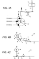
- FIG. 4A-4C show the relationship between the control shaft torque and the link geometry at various compression ratios and display the effects of reducing the bending load occurring in the actuator rod 33.
- FIG. 4A is a diagram that illustrates this relationship.
- the compression ratio is at a minimum when the eccentric axle 21 of the control shaft 20 is in position A, and the compression ratio is at a maximum when the eccentric axle 21 is in position C, as shown in FIG. 4A .
- the compression ratio is intermediate when the eccentric axle 21 is in position B. Therefore, as the compression ratio changes from the lowest level (position A) toward an intermediate level (position B), there is an increase in the effective arm length L over which the load F0 transmitted from the control link 15 is converted to the control shaft torque Tcs about the shaft-controlling axle 22.
- the effective arm length L decreases as the compression ratio changes from the intermediate level (position B) toward a maximum level (position C). Therefore, the control shaft torque Tcs is greatest at an intermediate compression ratio at which the effective arm length L is at a maximum.
- the link geometry of the shaft control mechanism 30 at an intermediate compression ratio is set so that the angle ⁇ a formed by the connecting link 31 and the intermediate control link 32 is greater than 90°, and the angle ⁇ b formed by the intermediate control link 32 and the actuator rod 33 is less than 180°, as shown in FIG. 4B .
- the control shaft torque Tcs causes the connecting link 31 to be subjected to a load F1 in the axial direction of the connecting link 31 and a load F2 in a direction orthogonal to the connecting link 31.
- the load F1 and the load F2 cause a tensile load F3 to act on the intermediate control link 32 in the axial direction of the intermediate control link 32.
- the actuator rod 33 is thereupon subjected to the tensile load F3 from the intermediate control link 32, and a tensile load F4 acts in the axial direction of the actuator rod 33 while a bending load F5 acts in a direction orthogonal (upward in the diagram) to the axial direction of the actuator rod 33.
- a bending load F5 on the actuator rod 33 also increases at an intermediate compression ratio at which the control shaft torque Tcs is at a maximum, and friction between the actuator rod 33 and the ball screw nut 34 therefore becomes extremely large. Accordingly, when the control shaft 20 is held, the load of the drive motor 35 increases with the loads on the link geometry of the shaft control mechanism 30 such as the one shown in FIG. 4B .
- the control shaft torque Tcs causes a tensile load F2 to act on the intermediate control link 32 in the axial direction of the intermediate control link 32, as shown in FIG. 4C . Since the angle ⁇ b formed by the intermediate control link 32 and the actuator rod 33 is substantially 180°, the tensile load F2 acts unchanged on the actuator rod 33 as well. Thus, in the present embodiment, the load produced on the actuator rod 33 by the control shaft torque Tcs at an intermediate compression ratio acts only in the axial direction of the actuator rod 33.
- the compression ratio at a high compression ratio is kept lower than at an intermediate compression ratio, the compression ratio can be rapidly changed from a high compression ratio to an intermediate compression ratio even in cases in which the vehicle suddenly accelerates from a low rotational speed or a low-load operating area, which is a state having a high compression ratio. The occurrence of knocking can thereby be reduced.
- the compression ratio at a low compression ratio is kept below that at an intermediate compression ratio, the compression ratio can be rapidly changed in accordance with the operating state of the engine even at a low compression ratio, and the effects of improving fuel consumption performance by lowering the compression ratio are greater.
- the reduction ratio is greater at an intermediate compression ratio than at a high compression ratio and a low compression ratio, the drive torque Tm needed for the drive motor 35 to rotate the control shaft 20 during changes to the compression ratio can be reduced. Therefore, increases in the load of the drive motor 35 can be reduced when the compression ratio is changed to an intermediate level.
- the link geometry of the shaft control mechanism 30 at an intermediate compression ratio is such that the intermediate control link 32 and the actuator rod 33 are nearly parallel, the bending load acting on the actuator rod 33 can be reduced. Therefore, when the control shaft 20 is held against the control shaft torque Tcs, the increased load of the drive motor 35 can be suppressed even at an intermediate compression ratio at which the control shaft torque Tcs is at a maximum.
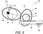
- FIG. 5 a second embodiment of a reduction mechanism for the multi-link variable compression ratio engine 1 shown in FIG. 1 will now be explained.
- the control shaft 20 and the reduction mechanism 31-34 of the first embodiment are replaced in FIG. 1 with a modified structure as discussed below.
- the descriptions of the parts of the second embodiment that are identical to the parts of the first embodiment may be omitted for the sake of brevity.
- a shaft control mechanism 130 with a reduction mechanism for the multi-link variable compression ratio engine 1 shown in FIG. 1 will now be explained.
- variable compression ratio engine 1 of the second embodiment is substantially the same as that of the first embodiment, but differs in the configuration of the shaft control mechanism 130.
- the reduction mechanism is configured from an elliptically shaped shaft-side pinion gear 23 formed on the control shaft 120, and an elliptically shaped drive gear 50 meshed with the shaft-side pinion gear 23.
- the shaft control mechanism 130 comprises the control shaft 120, a drive gear 50, and a rack gear 60 as shown in FIG. 5 .
- the control shaft 120 has an elliptically shaped shaft-side pinion gear 23.
- the shaft-side pinion gear 23 turns integrally with the control shaft 120, and turns around the axial center P of the control shaft 120.
- An eccentric axle 21 connected to a control link 15 is eccentric by a predetermined amount from the axial center P of the control shaft 120 so as to be positioned along the major axis of the shaft-side pinion gear 23, as seen from the axial direction of the control shaft.
- the drive gear 50 has an elliptically shaped drive-side pinion gear 51 and a circularly shaped pinion gear 52.
- the drive-side pinion gear 51 meshes with the shaft-side pinion gear 23.
- the drive-side pinion gear 51 and the circular pinion gear 52 are formed so that their axial centers coincide with each other, and these two gears rotate around an axial center Q.
- the circular pinion gear 52 meshes with the rack gear 60.
- the rack gear 60 in meshing engagement with the circular pinion gear 52 is shaped as a rod in the form of a flat plate, and is adapted to be advanced and retracted to the left and right of the drawing by the drive motor 35.
- the shaft control mechanism 130 configured as described above controls the angle of rotation of the control shaft 120 and varies the compression ratio by linearly advancing and retracting the rack gear 60 in accordance with the operating state of the engine.
- the action of the shaft control mechanism 130 is described with reference to FIG. 6A-6C.
- FIG. 6A shows the arrangement of the shaft-side pinion gear 23 and the drive-side pinion gear 51 at an intermediate compression ratio.
- FIG. 6B shows the arrangement of the shaft-side pinion gear 23 and the drive-side pinion gear 51 at a high compression ratio
- FIG. 6C shows the arrangement of the shaft-side pinion gear 23 and the drive-side pinion gear 51 at a low compression ratio.
- the major axis of the shaft-side pinion gear 23 and the minor axis of the drive-side pinion gear 51 are arranged so as to coincide with each other, as shown in FIG. 6A .
- the rotation of the drive motor 35 is transmitted to the control shaft 120 via the rack gear 60 and the drive gear 50, but since the minor axis of the drive-side pinion gear 51 and the major axis of the shaft-side pinion gear 23 are arranged so as to coincide with each other at an intermediate compression ratio, the rotational speed of the drive motor 35 is greatly reduced between the drive-side pinion gear 51 and the shaft-side pinion gear 23.
- the compression ratio changes from an intermediate level to a high level
- the position where the drive-side pinion gear 51 and the shaft-side pinion gear 23 mesh with each other changes from the minor axis side to the major axis side in the drive-side pinion gear 51, and from the major axis side to the minor axis side in the shaft-side pinion gear 23. Therefore, the reduction ratio between the drive motor 35 and the control shaft 120 is less than at an intermediate compression ratio.
- the compression ratio changes from an intermediate level to a low level
- the position where the drive-side pinion gear 51 and the shaft-side pinion gear 23 mesh with each other changes from the minor axis side to the major axis side in the drive-side pinion gear 51, and from the major axis side to the minor axis side in the shaft-side pinion gear 23. Therefore, the reduction ratio between the drive motor 35 and the control shaft 120 is less than at an intermediate compression ratio.
- the minor axis of the drive-side pinion gear 51 is arranged so as to coincide with the major axis of the shaft-side pinion gear 23 at an intermediate compression ratio, whereby the reduction ratio at a high compression ratio can be kept less than that at an intermediate compression ratio, and the same effects as in the first embodiment can therefore be achieved.
Landscapes
- Engineering & Computer Science (AREA)
- Chemical & Material Sciences (AREA)
- Combustion & Propulsion (AREA)
- Mechanical Engineering (AREA)
- General Engineering & Computer Science (AREA)
- Output Control And Ontrol Of Special Type Engine (AREA)
- Transmission Devices (AREA)
- Shafts, Cranks, Connecting Bars, And Related Bearings (AREA)
Claims (10)
- Vorrichtung für einen Motor (1) mit einer Kurbelwelle (12), einem Zylinder und einem Kolben (11), der mit der Kurbelwelle (12) derart in Wirkverbindung steht, dass er sich innerhalb des Zylinders hin und her bewegt, wobei die Vorrichtung umfasst:eine Steuerungswelle (20), die drehbar an dem Motor (1) gehaltert ist, wobei die Steuerungswelle (20) eine Exzenterachse (21) aufweist, die relativ zu einer zentralen Drehachse der Steuerungswelle (20) exzentrisch angeordnet ist;eine Koppelung zur Herstellung einer Wirkverbindung zwischen dem Kolben (11) und der Kurbelwelle (12) und zwischen der Kurbelwelle (12) und der Exzenterachse (21) der Steuerungswelle (20);einen Antriebsmotor (35), der mit der Steuerungswelle (20) derart in Wirkverbindung steht, dass sich die Steuerungswelle (20) derart um die zentrale Drehachse dreht, dass eine obere Totpunktposition des Kolbens (11) derart verändert wird, dass ein Kompressionsverhältnis des Motors (1) variiert wird; undeinen Reduktionsmechanismus (30), der den Antriebsmotor (35) mit der Steuerungswelle (20) verbindet und derart ausgebildet ist, dass die Drehung des Antriebsmotors (35) reduziert wird und die Drehung auf die Steuerungswelle (20) derart übertragen wird, dass ein Reduktionsverhältnis zwischen einem Drehwinkel des Antriebsmotors (35) und einem Drehwinkel der Steuerungswelle (20) bei einem hohen Kompressionsverhältnis geringer ist als bei einem Zwischenkompressionsverhältnis,wobei der Reduktionsmechanismus (30) derart ausgebildet ist, dass das Reduktionsverhältnis bei einem niedrigen Kompressionsverhältnis geringer ist als bei dem Zwischenkompressionsverhältnis.
- Vorrichtung gemäß Anspruch 1, wobei der Reduktionsmechanismus (30) eine mit der Koppelung verbundene Betätigungsstange (33) zur Drehung der Steuerungswelle (20) umfasst und dazu ausgebildet ist, von dem Antriebsmotor (35) vor und zurück in eine sich senkrecht zur Steuerungswelle (20) erstreckenden Richtung zu bewegen;
wobei der Antriebsmotor (35) dazu ausgebildet ist die Betätigungsstange (33) entsprechend eines Betriebszustands des Motors (1) vor und zurück zu bewegen und die Steuerungswelle (20) über die Koppelung zu drehen, um das Kompressionsverhältnis des Motors (1) zu variieren. - Vorrichtung gemäß Anspruch 2, wobei der Reduktionsmechanismus (30) einen Gewindetriebmechanismus zur Verbindung der Betätigungsstange (33) mit dem Antriebsmotor (35) mittels einer Schraubenstruktur umfasst zur Übertragung der Drehbewegung des Antriebsmotors (35) auf die Betätigungsstange (33), um die Betätigungsstange (33) vorwärts und rückwärts zu bewegen.
- Vorrichtung gemäß einem der vorhergehenden Ansprüche, wobei der Reduktionsmechanismus (30) umfasst:ein wellenseitiges, elliptisch ausgebildetes Zahnradgetriebe (23), dass auf der Steuerungswelle (20) zur integralen Rotation mit der Steuerungswelle (20) angebracht ist; undein antriebsseitiges, elliptisch ausgebildetes Zahnradgetriebe (51), das mit dem wellenseitigen Zahnradgetriebe (23) in Eingriff steht und von dem Antriebsmotor (35) gedreht wird;wobei der Antriebsmotor (35) dazu ausgebildet ist, das antriebsseitige Zahnradgetriebe (51) entsprechend eines Betriebszustands des Motors (1) zu drehen und die Steuerungswelle (20) mittels des wellenseitigen Zahnradgetriebes (23) zu drehen, um das Kompressionsverhältnis des Motors (1) zu variieren.
- Vorrichtung gemäß Anspruch 4, wobei das wellenseitige Zahnradgetriebe (23) und das antriebsseitige Zahnradgetriebe (51) derart angeordnet sind, dass eine Hauptachse des wellenseitigen Zahnradgetriebes (23) und eine Nebenachse des antriebsseitigen Zahnradgetriebes (51) bei einem Zwischenkompressionsverhältnis des Motors (1) im Wesentlichen zusammenfallen.
- Vorrichtung gemäß einem der vorhergehenden Ansprüche, wobei die Koppelung umfasst:eine obere Verbindung (13), die drehbar an dem Kolben (11) über einen Kolbenzapfen angebracht ist;eine untere Verbindung (14), die drehbar an einem Kurbelzapfen (12a) der Kurbelwelle (12) angebracht ist und drehbar mit der oberen Verbindung (13) über einen oberen Zapfen (14a) verbunden ist; undeine Steuerungsverbindung (15), die an einem Ende drehbar mit der unteren Verbindung (14) über einen Steuerungszapfen (14b) und an dem anderen Ende drehbar mit der Exzenterachse (21) der Steuerungswelle (20) verbunden ist.
- Vorrichtung gemäß Anspruch 6, wobei der Reduktionsmechanismus (30) umfasst:eine Zwischensteuerungsverbindung (32), die mit der Steuerungswelle (20) in einer zur zentralen Drehachse der Steuerungswelle (20) versetzten Position angeordnet ist; undein Verbindungsglied (31), das mit der Zwischensteuerungsverbindung (32) an einem Ende des Verbindungsglieds (31) und mit der Steuerungswelle (20) an einem anderen Ende des Verbindungsglieds (31) verbunden ist;wobei die Zwischensteuerungsverbindung (32), das Verbindungsglied (31) und die Betätigungsstange (33) derart angeordnet sind, dass bei einem Zwischenkompressionsverhältnis ein 180°-Winkel von der Steuerungswelle (20) und dem Verbindungsglied (31) gebildet wird, ein 90°-Winkel von dem Verbindungsglied (31) und der Zwischensteuerungsverbindung (32) gebildet wird und ein 180°-Winkel von der Zwischensteuerungsverbindung (32) und der Betätigungsstange (33) gebildet wird.
- Vorrichtung gemäß einem der vorhergehenden Ansprüche, wobei der Antriebsmotor (35) dazu ausgebildet ist, die Steuerungswelle (20) um die zentrale Drehachse zur Veränderung zu drehen, um die Position der Exzenterachse (21) und die Orientierungen der Kopplung zu verändern.
- Motor (1), der eine Vorrichtung gemäß einem der vorhergehenden Ansprüche aufweist.
- Fahrzeug, das eine Vorrichtung gemäß einem der Ansprüche 1 bis 8 oder einen Motor (1) gemäß Anspruch 9 aufweist.
Applications Claiming Priority (1)
| Application Number | Priority Date | Filing Date | Title |
|---|---|---|---|
| JP2007280370A JP5029290B2 (ja) | 2007-10-29 | 2007-10-29 | 可変圧縮比エンジン |
Publications (3)
| Publication Number | Publication Date |
|---|---|
| EP2055914A2 EP2055914A2 (de) | 2009-05-06 |
| EP2055914A3 EP2055914A3 (de) | 2012-03-28 |
| EP2055914B1 true EP2055914B1 (de) | 2018-07-25 |
Family
ID=40139290
Family Applications (1)
| Application Number | Title | Priority Date | Filing Date |
|---|---|---|---|
| EP08167313.9A Ceased EP2055914B1 (de) | 2007-10-29 | 2008-10-22 | Mehrfachverbindungs-Motor mit variablem Verdichtungsverhältnis |
Country Status (3)
| Country | Link |
|---|---|
| US (1) | US8087390B2 (de) |
| EP (1) | EP2055914B1 (de) |
| JP (1) | JP5029290B2 (de) |
Families Citing this family (59)
| Publication number | Priority date | Publication date | Assignee | Title |
|---|---|---|---|---|
| US7011600B2 (en) | 2003-02-28 | 2006-03-14 | Fallbrook Technologies Inc. | Continuously variable transmission |
| MX364884B (es) | 2004-10-05 | 2019-05-10 | Fallbrook Intellectual Property Company Llc Star | Transmisión continuamente variable. |
| KR20130018976A (ko) | 2005-10-28 | 2013-02-25 | 폴브룩 테크놀로지즈 인크 | 전기 기계 동력 전달 방법 |
| US20070155567A1 (en) | 2005-11-22 | 2007-07-05 | Fallbrook Technologies Inc. | Continuously variable transmission |
| CN102226464B (zh) | 2005-12-09 | 2013-04-17 | 福博科技术公司 | 一种用于变速器的轴向力产生机构 |
| EP1811202A1 (de) * | 2005-12-30 | 2007-07-25 | Fallbrook Technologies, Inc. | Stufenloses Getriebe |
| US7882762B2 (en) | 2006-01-30 | 2011-02-08 | Fallbrook Technologies Inc. | System for manipulating a continuously variable transmission |
| CN102269056B (zh) | 2006-06-26 | 2013-10-23 | 福博科技术公司 | 无级变速器 |
| EP2089642B1 (de) | 2006-11-08 | 2013-04-10 | Fallbrook Intellectual Property Company LLC | Klemmkraftgenerator |
| EP2125469A2 (de) | 2007-02-01 | 2009-12-02 | Fallbrook Technologies Inc. | System und verfahren zur getriebe- und/oder antriebsmotorsteuerung |
| CN101657653B (zh) | 2007-02-12 | 2014-07-16 | 福博科知识产权有限责任公司 | 一种传动装置 |
| WO2008101070A2 (en) | 2007-02-16 | 2008-08-21 | Fallbrook Technologies Inc. | Infinitely variable transmissions, continuously variable transmissions, methods, assemblies, subassemblies, and components therefor |
| EP2142826B1 (de) | 2007-04-24 | 2015-10-28 | Fallbrook Intellectual Property Company LLC | Elektrische zugvorrichtungen |
| US8641577B2 (en) | 2007-06-11 | 2014-02-04 | Fallbrook Intellectual Property Company Llc | Continuously variable transmission |
| KR20100046166A (ko) | 2007-07-05 | 2010-05-06 | 폴브룩 테크놀로지즈 인크 | 연속 가변 변속기 |
| JP4882912B2 (ja) * | 2007-08-10 | 2012-02-22 | 日産自動車株式会社 | 可変圧縮比内燃機関 |
| CN103939602B (zh) | 2007-11-16 | 2016-12-07 | 福博科知识产权有限责任公司 | 用于变速传动装置的控制器 |
| EP2234869B1 (de) | 2007-12-21 | 2012-07-04 | Fallbrook Technologies Inc. | Automatikgetriebe und verfahren dafür |
| WO2009111328A1 (en) | 2008-02-29 | 2009-09-11 | Fallbrook Technologies Inc. | Continuously and/or infinitely variable transmissions and methods therefor |
| US8317651B2 (en) | 2008-05-07 | 2012-11-27 | Fallbrook Intellectual Property Company Llc | Assemblies and methods for clamping force generation |
| JP5457438B2 (ja) | 2008-06-06 | 2014-04-02 | フォールブルック インテレクチュアル プロパティー カンパニー エルエルシー | 無限可変変速機、及び無限可変変速機用の制御システム |
| CN107246463A (zh) | 2008-06-23 | 2017-10-13 | 福博科知识产权有限责任公司 | 无级变速器 |
| WO2010017242A1 (en) | 2008-08-05 | 2010-02-11 | Fallbrook Technologies Inc. | Methods for control of transmission and prime mover |
| US8469856B2 (en) | 2008-08-26 | 2013-06-25 | Fallbrook Intellectual Property Company Llc | Continuously variable transmission |
| US8167759B2 (en) | 2008-10-14 | 2012-05-01 | Fallbrook Technologies Inc. | Continuously variable transmission |
| KR101718754B1 (ko) | 2009-04-16 | 2017-03-22 | 폴브룩 인텔렉츄얼 프로퍼티 컴퍼니 엘엘씨 | 무단 변속기를 위한 고정자 조립체 및 시프팅 장치 |
| KR101509664B1 (ko) | 2009-10-06 | 2015-04-08 | 현대자동차 주식회사 | 가변 압축비 장치 |
| US8512195B2 (en) | 2010-03-03 | 2013-08-20 | Fallbrook Intellectual Property Company Llc | Infinitely variable transmissions, continuously variable transmissions, methods, assemblies, subassemblies, and components therefor |
| JP5146598B2 (ja) * | 2010-03-29 | 2013-02-20 | トヨタ自動車株式会社 | 車両の制御装置 |
| US8888643B2 (en) | 2010-11-10 | 2014-11-18 | Fallbrook Intellectual Property Company Llc | Continuously variable transmission |
| WO2012138610A1 (en) | 2011-04-04 | 2012-10-11 | Fallbrook Intellectual Property Company Llc | Auxiliary power unit having a continuously variable transmission |
| JP6175450B2 (ja) | 2012-01-23 | 2017-08-02 | フォールブルック インテレクチュアル プロパティー カンパニー エルエルシー | 無限可変変速機、連続可変変速機、方法、組立体、部分組立体およびその構成要素 |
| DE102012001648B4 (de) * | 2012-01-27 | 2014-04-30 | Audi Ag | Mehrgelenkskurbeltrieb einer Brennkraftmaschine sowie Verfahren zur Montage eines Mehrgelenkskurbeltriebs |
| JP6024221B2 (ja) * | 2012-06-06 | 2016-11-09 | 日産自動車株式会社 | 可変圧縮比内燃機関 |
| US9140182B2 (en) * | 2013-02-22 | 2015-09-22 | Hyundai Motor Company | Variable compression ratio control system |
| CN109018173B (zh) | 2013-04-19 | 2021-05-28 | 福博科知识产权有限责任公司 | 无级变速器 |
| KR101500392B1 (ko) | 2013-12-13 | 2015-03-09 | 현대자동차 주식회사 | 가변 압축비 장치 |
| JP6204834B2 (ja) * | 2014-01-14 | 2017-09-27 | 本田技研工業株式会社 | 無段変速機 |
| US10215090B2 (en) | 2015-07-03 | 2019-02-26 | Board Of Regents, The University Of Texas System | Combustion engine linkage systems |
| US10047861B2 (en) | 2016-01-15 | 2018-08-14 | Fallbrook Intellectual Property Company Llc | Systems and methods for controlling rollback in continuously variable transmissions |
| DE102016201035A1 (de) * | 2016-01-26 | 2017-07-27 | Schaeffler Technologies AG & Co. KG | Hubkolbenbrennkraftmaschine mit veränderlichem Verdichtungsverhältnis |
| US10458526B2 (en) | 2016-03-18 | 2019-10-29 | Fallbrook Intellectual Property Company Llc | Continuously variable transmissions, systems and methods |
| US10125679B2 (en) * | 2016-03-29 | 2018-11-13 | GM Global Technology Operations LLC | Independent compression and expansion ratio engine with variable compression ratio |
| US10023266B2 (en) | 2016-05-11 | 2018-07-17 | Fallbrook Intellectual Property Company Llc | Systems and methods for automatic configuration and automatic calibration of continuously variable transmissions and bicycles having continuously variable transmissions |
| MX2019006606A (es) * | 2016-12-13 | 2019-08-14 | Nissan Motor | Metodo de control y dispositivo de control de motor de combustion interna. |
| US10273927B2 (en) | 2017-03-01 | 2019-04-30 | Ford Global Technologies, Llc | Controlling variable compression ratio with a pressure-reactive piston |
| US10378459B2 (en) | 2017-03-23 | 2019-08-13 | Ford Global Technologies, Llc | Method and system for engine control |
| US10202898B2 (en) | 2017-04-25 | 2019-02-12 | Ford Global Technologies, Llc | Method and system for fuel injection control |
| US10202912B2 (en) | 2017-06-20 | 2019-02-12 | Ford Global Technologies, Llc | System and method for reducing variable compression ratio engine shutdown shake |
| KR102406127B1 (ko) * | 2017-10-16 | 2022-06-07 | 현대자동차 주식회사 | 가변 압축비 엔진 |
| CN108412611A (zh) * | 2018-04-04 | 2018-08-17 | 吉林大学 | 一种内置电机驱动式可变长度连杆 |
| US10677157B2 (en) * | 2018-09-07 | 2020-06-09 | Ford Global Technologies, Llc | Variable compression ratio engine with mechanical locking pin |
| US11215268B2 (en) | 2018-11-06 | 2022-01-04 | Fallbrook Intellectual Property Company Llc | Continuously variable transmissions, synchronous shifting, twin countershafts and methods for control of same |
| CN110671197B (zh) * | 2018-12-29 | 2021-08-20 | 长城汽车股份有限公司 | 发动机及具有其的车辆 |
| US10927754B2 (en) | 2019-01-28 | 2021-02-23 | International Engine Intellectual Property Company, Llc | Engine having a variable compression ratio |
| US11174922B2 (en) | 2019-02-26 | 2021-11-16 | Fallbrook Intellectual Property Company Llc | Reversible variable drives and systems and methods for control in forward and reverse directions |
| US10760481B1 (en) | 2019-07-17 | 2020-09-01 | Hyundai Motor Company | Magnetically-actuated variable-length connecting rod devices and methods for controlling the same |
| US11149782B2 (en) | 2019-07-17 | 2021-10-19 | Hyundai Motor Company | Magnetically-actuated variable-length connecting rod devices and methods for controlling the same |
| US11215113B2 (en) | 2019-07-17 | 2022-01-04 | Hyundai Motor Company | Magnetically-actuated variable-length connecting rod devices and methods for controlling the same |
Citations (1)
| Publication number | Priority date | Publication date | Assignee | Title |
|---|---|---|---|---|
| EP2022959A2 (de) * | 2007-08-10 | 2009-02-11 | Nissan Motor Company Limited | Variable Druckverhältnisvorrichtung für einen Verbrennungsmotor |
Family Cites Families (19)
| Publication number | Priority date | Publication date | Assignee | Title |
|---|---|---|---|---|
| US6260532B1 (en) * | 1998-09-28 | 2001-07-17 | Edward Charles Mendler | Rigid crankshaft cradle and actuator |
| JP2001227367A (ja) * | 2000-02-16 | 2001-08-24 | Nissan Motor Co Ltd | レシプロ式内燃機関 |
| JP3968957B2 (ja) * | 2000-06-02 | 2007-08-29 | 日産自動車株式会社 | 内燃機関 |
| JP3968967B2 (ja) * | 2000-07-07 | 2007-08-29 | 日産自動車株式会社 | レシプロ式内燃機関の可変圧縮比機構 |
| JP3911977B2 (ja) | 2000-08-17 | 2007-05-09 | 日産自動車株式会社 | 内燃機関の複リンク機構 |
| JP3941371B2 (ja) * | 2000-10-12 | 2007-07-04 | 日産自動車株式会社 | 内燃機関の可変圧縮比機構 |
| JP3879385B2 (ja) * | 2000-10-31 | 2007-02-14 | 日産自動車株式会社 | 内燃機関の可変圧縮比機構 |
| JP2002227674A (ja) * | 2001-02-06 | 2002-08-14 | Nissan Motor Co Ltd | 内燃機関の可変圧縮比機構 |
| JP2003287100A (ja) * | 2002-03-28 | 2003-10-10 | Nsk Ltd | リニアアクチュエータ |
| JP2003322036A (ja) * | 2002-05-07 | 2003-11-14 | Nissan Motor Co Ltd | 内燃機関の可変圧縮比機構 |
| JP4136602B2 (ja) * | 2002-10-30 | 2008-08-20 | トヨタ自動車株式会社 | エンジンの圧縮比変更方法と可変圧縮比エンジン |
| JP4333129B2 (ja) * | 2002-12-05 | 2009-09-16 | トヨタ自動車株式会社 | エンジンの圧縮比変更方法と可変圧縮比エンジン |
| JP4120512B2 (ja) * | 2003-08-27 | 2008-07-16 | 日産自動車株式会社 | 内燃機関の可変圧縮比機構及びそのピストン位置較正方法 |
| JP4387770B2 (ja) | 2003-11-19 | 2009-12-24 | 日産自動車株式会社 | 内燃機関 |
| JP4341392B2 (ja) | 2003-12-05 | 2009-10-07 | 日産自動車株式会社 | 内燃機関の可変圧縮比装置 |
| JP4403885B2 (ja) * | 2004-06-04 | 2010-01-27 | 日産自動車株式会社 | 複リンク式ピストンクランク機構を備えたエンジン |
| JP4165506B2 (ja) | 2004-12-28 | 2008-10-15 | 日産自動車株式会社 | 内燃機関 |
| JP4516864B2 (ja) * | 2005-03-15 | 2010-08-04 | 日産自動車株式会社 | 内燃機関の可変圧縮比装置 |
| KR100754214B1 (ko) | 2006-04-11 | 2007-09-03 | 삼성전자주식회사 | 네트워크에 연결된 디바이스간에 이벤트 정보 전송 방법 및장치와 그 저장 매체 |
-
2007
- 2007-10-29 JP JP2007280370A patent/JP5029290B2/ja not_active Expired - Fee Related
-
2008
- 2008-10-22 EP EP08167313.9A patent/EP2055914B1/de not_active Ceased
- 2008-10-22 US US12/255,751 patent/US8087390B2/en not_active Expired - Fee Related
Patent Citations (1)
| Publication number | Priority date | Publication date | Assignee | Title |
|---|---|---|---|---|
| EP2022959A2 (de) * | 2007-08-10 | 2009-02-11 | Nissan Motor Company Limited | Variable Druckverhältnisvorrichtung für einen Verbrennungsmotor |
Also Published As
| Publication number | Publication date |
|---|---|
| JP2009108730A (ja) | 2009-05-21 |
| US8087390B2 (en) | 2012-01-03 |
| EP2055914A2 (de) | 2009-05-06 |
| EP2055914A3 (de) | 2012-03-28 |
| US20090107454A1 (en) | 2009-04-30 |
| JP5029290B2 (ja) | 2012-09-19 |
Similar Documents
| Publication | Publication Date | Title |
|---|---|---|
| EP2055914B1 (de) | Mehrfachverbindungs-Motor mit variablem Verdichtungsverhältnis | |
| JP4882912B2 (ja) | 可変圧縮比内燃機関 | |
| US7681538B2 (en) | Internal combustion engine employing variable compression ratio mechanism | |
| JP6024221B2 (ja) | 可変圧縮比内燃機関 | |
| EP2053217B1 (de) | Mehrfachverbindungs-Motor | |
| JP2002115571A (ja) | 内燃機関の可変圧縮比機構 | |
| JP2009041511A5 (de) | ||
| EP2960466B1 (de) | Verbrennungsmotor mit variabler verdichtung | |
| JP5182167B2 (ja) | 可変圧縮比機構 | |
| EP2016265B1 (de) | Brennkraftmaschine mit variablem kompressionsverhältnis | |
| US9863311B2 (en) | Variable compression ratio internal combustion engine | |
| JP5115643B2 (ja) | 可変圧縮比内燃機関 | |
| JP2001263114A (ja) | 可変圧縮比機構を備えた内燃機関 | |
| JP4924479B2 (ja) | 可変圧縮比内燃機関 | |
| JP2011252508A (ja) | 可変圧縮比内燃機関 | |
| CN112984069A (zh) | 一种抗高过载舵系统 | |
| JP4491426B2 (ja) | 内燃機関の可変圧縮比機構 | |
| JP2007247538A (ja) | 内燃機関の可変圧縮比機構 | |
| JP2009108731A (ja) | 可変圧縮比エンジン | |
| JP4714609B2 (ja) | 内燃機関の可変圧縮比機構 | |
| CN222122020U (zh) | 发动机的连杆组件、发动机以及车辆 | |
| JP2011252504A (ja) | 可変圧縮比内燃機関 | |
| JP2011252507A (ja) | 可変圧縮比内燃機関 | |
| CN201688008U (zh) | 一种阀门电动装置的传动机构 | |
| JP5227654B2 (ja) | 油圧ガバナ |
Legal Events
| Date | Code | Title | Description |
|---|---|---|---|
| PUAI | Public reference made under article 153(3) epc to a published international application that has entered the european phase |
Free format text: ORIGINAL CODE: 0009012 |
|
| AK | Designated contracting states |
Kind code of ref document: A2 Designated state(s): AT BE BG CH CY CZ DE DK EE ES FI FR GB GR HR HU IE IS IT LI LT LU LV MC MT NL NO PL PT RO SE SI SK TR |
|
| AX | Request for extension of the european patent |
Extension state: AL BA MK RS |
|
| PUAL | Search report despatched |
Free format text: ORIGINAL CODE: 0009013 |
|
| RIC1 | Information provided on ipc code assigned before grant |
Ipc: F02B 75/04 20060101AFI20120216BHEP |
|
| AK | Designated contracting states |
Kind code of ref document: A3 Designated state(s): AT BE BG CH CY CZ DE DK EE ES FI FR GB GR HR HU IE IS IT LI LT LU LV MC MT NL NO PL PT RO SE SI SK TR |
|
| AX | Request for extension of the european patent |
Extension state: AL BA MK RS |
|
| 17P | Request for examination filed |
Effective date: 20120619 |
|
| AKX | Designation fees paid |
Designated state(s): DE FR GB |
|
| STAA | Information on the status of an ep patent application or granted ep patent |
Free format text: STATUS: EXAMINATION IS IN PROGRESS |
|
| 17Q | First examination report despatched |
Effective date: 20170215 |
|
| GRAP | Despatch of communication of intention to grant a patent |
Free format text: ORIGINAL CODE: EPIDOSNIGR1 |
|
| STAA | Information on the status of an ep patent application or granted ep patent |
Free format text: STATUS: GRANT OF PATENT IS INTENDED |
|
| INTG | Intention to grant announced |
Effective date: 20180425 |
|
| GRAS | Grant fee paid |
Free format text: ORIGINAL CODE: EPIDOSNIGR3 |
|
| GRAA | (expected) grant |
Free format text: ORIGINAL CODE: 0009210 |
|
| STAA | Information on the status of an ep patent application or granted ep patent |
Free format text: STATUS: THE PATENT HAS BEEN GRANTED |
|
| AK | Designated contracting states |
Kind code of ref document: B1 Designated state(s): DE FR GB |
|
| REG | Reference to a national code |
Ref country code: GB Ref legal event code: FG4D |
|
| REG | Reference to a national code |
Ref country code: DE Ref legal event code: R096 Ref document number: 602008056128 Country of ref document: DE |
|
| REG | Reference to a national code |
Ref country code: FR Ref legal event code: PLFP Year of fee payment: 11 |
|
| REG | Reference to a national code |
Ref country code: DE Ref legal event code: R097 Ref document number: 602008056128 Country of ref document: DE |
|
| PLBE | No opposition filed within time limit |
Free format text: ORIGINAL CODE: 0009261 |
|
| STAA | Information on the status of an ep patent application or granted ep patent |
Free format text: STATUS: NO OPPOSITION FILED WITHIN TIME LIMIT |
|
| 26N | No opposition filed |
Effective date: 20190426 |
|
| PGFP | Annual fee paid to national office [announced via postgrant information from national office to epo] |
Ref country code: FR Payment date: 20210913 Year of fee payment: 14 |
|
| PGFP | Annual fee paid to national office [announced via postgrant information from national office to epo] |
Ref country code: GB Payment date: 20210915 Year of fee payment: 14 |
|
| PGFP | Annual fee paid to national office [announced via postgrant information from national office to epo] |
Ref country code: DE Payment date: 20210914 Year of fee payment: 14 |
|
| REG | Reference to a national code |
Ref country code: DE Ref legal event code: R119 Ref document number: 602008056128 Country of ref document: DE |
|
| GBPC | Gb: european patent ceased through non-payment of renewal fee |
Effective date: 20221022 |
|
| PG25 | Lapsed in a contracting state [announced via postgrant information from national office to epo] |
Ref country code: FR Free format text: LAPSE BECAUSE OF NON-PAYMENT OF DUE FEES Effective date: 20221031 Ref country code: DE Free format text: LAPSE BECAUSE OF NON-PAYMENT OF DUE FEES Effective date: 20230503 |
|
| PG25 | Lapsed in a contracting state [announced via postgrant information from national office to epo] |
Ref country code: GB Free format text: LAPSE BECAUSE OF NON-PAYMENT OF DUE FEES Effective date: 20221022 |