EP2055941A2 - Dispositif de ventilation pour le moyeu de rotor d'une éolienne - Google Patents
Dispositif de ventilation pour le moyeu de rotor d'une éolienne Download PDFInfo
- Publication number
- EP2055941A2 EP2055941A2 EP08015503A EP08015503A EP2055941A2 EP 2055941 A2 EP2055941 A2 EP 2055941A2 EP 08015503 A EP08015503 A EP 08015503A EP 08015503 A EP08015503 A EP 08015503A EP 2055941 A2 EP2055941 A2 EP 2055941A2
- Authority
- EP
- European Patent Office
- Prior art keywords
- rotor hub
- inlet opening
- air inlet
- ventilation
- base portion
- Prior art date
- Legal status (The legal status is an assumption and is not a legal conclusion. Google has not performed a legal analysis and makes no representation as to the accuracy of the status listed.)
- Granted
Links
Images

Classifications
-
- F—MECHANICAL ENGINEERING; LIGHTING; HEATING; WEAPONS; BLASTING
- F03—MACHINES OR ENGINES FOR LIQUIDS; WIND, SPRING, OR WEIGHT MOTORS; PRODUCING MECHANICAL POWER OR A REACTIVE PROPULSIVE THRUST, NOT OTHERWISE PROVIDED FOR
- F03D—WIND MOTORS
- F03D80/00—Details, components or accessories not provided for in groups F03D1/00 - F03D17/00
- F03D80/60—Cooling or heating of wind motors
-
- F—MECHANICAL ENGINEERING; LIGHTING; HEATING; WEAPONS; BLASTING
- F05—INDEXING SCHEMES RELATING TO ENGINES OR PUMPS IN VARIOUS SUBCLASSES OF CLASSES F01-F04
- F05B—INDEXING SCHEME RELATING TO WIND, SPRING, WEIGHT, INERTIA OR LIKE MOTORS, TO MACHINES OR ENGINES FOR LIQUIDS COVERED BY SUBCLASSES F03B, F03D AND F03G
- F05B2260/00—Function
- F05B2260/60—Fluid transfer
-
- F—MECHANICAL ENGINEERING; LIGHTING; HEATING; WEAPONS; BLASTING
- F05—INDEXING SCHEMES RELATING TO ENGINES OR PUMPS IN VARIOUS SUBCLASSES OF CLASSES F01-F04
- F05B—INDEXING SCHEME RELATING TO WIND, SPRING, WEIGHT, INERTIA OR LIKE MOTORS, TO MACHINES OR ENGINES FOR LIQUIDS COVERED BY SUBCLASSES F03B, F03D AND F03G
- F05B2260/00—Function
- F05B2260/60—Fluid transfer
- F05B2260/602—Drainage
-
- F—MECHANICAL ENGINEERING; LIGHTING; HEATING; WEAPONS; BLASTING
- F05—INDEXING SCHEMES RELATING TO ENGINES OR PUMPS IN VARIOUS SUBCLASSES OF CLASSES F01-F04
- F05B—INDEXING SCHEME RELATING TO WIND, SPRING, WEIGHT, INERTIA OR LIKE MOTORS, TO MACHINES OR ENGINES FOR LIQUIDS COVERED BY SUBCLASSES F03B, F03D AND F03G
- F05B2260/00—Function
- F05B2260/60—Fluid transfer
- F05B2260/64—Aeration, ventilation, dehumidification or moisture removal of closed spaces
-
- Y—GENERAL TAGGING OF NEW TECHNOLOGICAL DEVELOPMENTS; GENERAL TAGGING OF CROSS-SECTIONAL TECHNOLOGIES SPANNING OVER SEVERAL SECTIONS OF THE IPC; TECHNICAL SUBJECTS COVERED BY FORMER USPC CROSS-REFERENCE ART COLLECTIONS [XRACs] AND DIGESTS
- Y02—TECHNOLOGIES OR APPLICATIONS FOR MITIGATION OR ADAPTATION AGAINST CLIMATE CHANGE
- Y02E—REDUCTION OF GREENHOUSE GAS [GHG] EMISSIONS, RELATED TO ENERGY GENERATION, TRANSMISSION OR DISTRIBUTION
- Y02E10/00—Energy generation through renewable energy sources
- Y02E10/70—Wind energy
- Y02E10/72—Wind turbines with rotation axis in wind direction
Definitions
- the present invention relates to a device for ventilating a rotor hub of a wind turbine.
- the ventilation device has a cup-shaped element which has a bottom and a circumferential side wall. Further, a tubular neck is provided, which points into an interior of the rotor hub.
- the cup-shaped element is held by an inlet opening of the nozzle in such a way that the inlet opening is arranged within the cup-shaped element.
- an air flow passes the cup-shaped element in the tubular socket and thus ventilates the interior of the rotor hub.
- the position of the tubular nozzle in the cup-shaped member prevents the water from entering the interior of the rotor hub.
- the rotor hub not yet mounted is usually mounted on one side, which is provided for connection to the rotor shaft, so that the ventilation device faces upwards. It turned out that the DE 10 2004 058 776 B3 known ventilation device in this storage position of the rotor hub can not prevent water from entering the interior of the rotor hub.
- the invention has for its object to provide an improved ventilation device for the rotor hub of a wind turbine, which ensures that also located in the interior of a not yet mounted rotor hub components are protected from rain.
- the object is achieved by a device for ventilating a rotor hub of a wind turbine with the features of claim 1.
- the device according to the invention for ventilating a rotor hub of a wind power plant has a cup-shaped ventilation cover and a tubular connecting piece.
- the cup-shaped vent cover has a circumferential side wall and a base portion surrounded by the side wall.
- the side wall is provided with at least one drainage hole.
- the base portion of the vent cover has at least one vent for venting.
- the tubular nozzle has an air inlet opening and an air outlet opening, which opens into an interior of the rotor hub. About the tubular nozzle, the interior of the rotor hub is connected to the environment.
- the ventilation cover is arranged in front of the air inlet opening without this completely to close.
- the at least one bore for ventilation in the ventilation cover is arranged outside the air inlet opening of the tubular nozzle so that the air inlet opening is shielded by the ventilation cover.
- the air inlet opening of the nozzle is protected against direct entry of water, for example, rainwater by the ventilation cover obscures the air inlet opening of the nozzle and thus blocks a straight-line connection of the environment with the interior of the rotor hub.
- the ventilation cover has in its side wall at least one bore through which rainwater, which has collected between the nozzle and the ventilation cover, can be led out of the ventilation device again.
- the base portion of the ventilation cover is provided in a central portion without holes, wherein the diameter of the central portion is greater than the diameter of the air inlet opening of the tubular nozzle.
- the non-drilled central section conceals the air inlet opening.
- the base portion of the vent cover consists of a central portion and a transition portion.
- the central section is connected to the peripheral side wall via the transition section.
- the at least one ventilation bore of the base section is preferably arranged in the transition section.
- the central portion is lowered in the base portion relative to the side walls, and thus lies at a height between the upper edge and the lower edge of the side wall.
- the tubular connecting piece is widened funnel-shaped in the region of an air inlet opening.
- the funnel-shaped extension ensures that no water can penetrate into the nozzle during operation of the system.
- the nacelle and thus the hub of the wind turbine are mounted in a slight inclination upwards on the tower.
- the funnel opening is wide open so that the lower section of the funnel wall is slightly inclined downwards when the hub is mounted. Water impinging on the funnel wall thus flows out of the funnel opening into the interior of the ventilating device and out through a bore in the side wall. When driving rain, the water meets the wall section of the hub, runs past the ventilation pipe and also through the hole in the side wall to the outside.
- the tubular connecting piece protrudes from a wall section of the rotor hub, on which the ventilation cover is also held.
- the wall portion is formed as a closable door member to gain access to the interior of the rotor hub.
- the wall material is made of a transparent material.
- transparent material allows light to enter the interior of the rotor hub and at the same time creates the opportunity to inspect the space under the ventilation cover.
- FIG. 1 shows the structure of the ventilation device according to the invention in cross section.
- the ventilation device consists of a ventilation cover 10, which is arranged above a ventilation stub 12.
- the ventilation pipe 12 is held in a wall portion 14 of the rotor hub.
- the vent cover 10 has a circumferential side wall 16 which is secured with an angled edge portion 18 on the outer wall of the rotor housing.
- the side wall has a curved portion 20 which forms a circumferential ring.
- the base portion 22 of the vent cover Within the ring 20 is the base portion 22 of the vent cover.
- the base portion 22 has a transition portion 24 and a horizontal portion 26. In the transition portion 24 vent holes 28 are provided.
- the nozzle 12 which is arranged concentrically under the ventilation cover 10, has a funnel-shaped widening section 30, which forms the air inlet opening.
- a drainage bore 32 in the side wall 16 is provided below an upper edge 34 of the funnel-shaped widening area.
- the ventilation device has the in the FIG. 1 shown position. In this position it is ensured that incoming water does not enter the interior of the rotor hub.
- the rainwater entering via the ventilation bore 28 collects in the space between the nozzle 12 and the ventilation cover 10. Before the water reaches a height which allows it to enter the interior of the rotor hub via the edge 34, the water flows over the Drainage hole 32 again.
- FIG. 2 shows a ventilation device of the prior art.
- a cup-shaped cover member 35 is provided, which is arranged via a funnel-shaped nozzle 36.
- Incident rainwater 38 can collect in a holder 40 for the nozzle 36 and enter the interior of the rotor hub over the edge of the nozzle. Such ingress of water can lead to damage of already mounted components in the rotor hub.
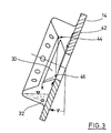
- FIG. 3 The operation of the ventilation device according to the invention in its mounted position will be off FIG. 3 clear.
- the nacelle and thus the hub of the wind turbine is mounted in a slight inclination up the tower.
- the inclination is in Fig. 3 indicated by the angle ⁇ relative to the Lot.
- a liquid entry into the aeration device can lead to a liquid amount 42 which collects on the wall portion 14 of the rotor hub.
- the amount of liquid 42 flows under the action of gravity down and can escape through the drainage hole 32.
- an amount of liquid 44 may collect on the inside of the vent cover. In the worst case, this amount of liquid drips 44 in the funnel-shaped enlarged portion 30 of the neck 12.
- FIG. 3 As in FIG.
- the drained amount of liquid emerges from the funnel again under the action of gravity and can likewise exit from the aeration device via the drainage bore 32.
- the opening angle of the region 30 is greater than the inclination angle ⁇ of the rotor hub.
- the air flow into the hub is essentially due to a negative pressure in the hub. Due to the rotation of the rotor hub, a centrifugal force acts on the air mass, which is located in the rotor blade, which results in an increase of the air pressure in the rotor blade. This increased pressure relaxes through a hole in the wing tip, which is connected to the environment and there is an air flow through the wings to the outside. In the rotor hub thereby creates a negative pressure is sucked through the new air from the environment through the ventilation device through.
- the ventilation cover can thus be dimensioned much smaller.
- the volume of air in the hub is exchanged about three times per hour.
Landscapes
- Engineering & Computer Science (AREA)
- Physics & Mathematics (AREA)
- Thermal Sciences (AREA)
- Life Sciences & Earth Sciences (AREA)
- Sustainable Development (AREA)
- Sustainable Energy (AREA)
- Chemical & Material Sciences (AREA)
- Combustion & Propulsion (AREA)
- Mechanical Engineering (AREA)
- General Engineering & Computer Science (AREA)
- Wind Motors (AREA)
- Motor Or Generator Cooling System (AREA)
Applications Claiming Priority (1)
| Application Number | Priority Date | Filing Date | Title |
|---|---|---|---|
| DE102007052276A DE102007052276B3 (de) | 2007-10-31 | 2007-10-31 | Vorrichtung zur Belüftung einer Rotornabe einer Windenergieanlage |
Publications (3)
| Publication Number | Publication Date |
|---|---|
| EP2055941A2 true EP2055941A2 (fr) | 2009-05-06 |
| EP2055941A3 EP2055941A3 (fr) | 2011-06-15 |
| EP2055941B1 EP2055941B1 (fr) | 2013-08-21 |
Family
ID=39863088
Family Applications (1)
| Application Number | Title | Priority Date | Filing Date |
|---|---|---|---|
| EP08015503.9A Not-in-force EP2055941B1 (fr) | 2007-10-31 | 2008-09-03 | Dispositif de ventilation pour le moyeu de rotor d'une éolienne |
Country Status (3)
| Country | Link |
|---|---|
| US (1) | US8128368B2 (fr) |
| EP (1) | EP2055941B1 (fr) |
| DE (1) | DE102007052276B3 (fr) |
Cited By (1)
| Publication number | Priority date | Publication date | Assignee | Title |
|---|---|---|---|---|
| US10655599B2 (en) | 2013-12-27 | 2020-05-19 | DOOSAN Heavy Industries Construction Co., LTD | Wind farm, control method thereof and wind power generation unit |
Families Citing this family (10)
| Publication number | Priority date | Publication date | Assignee | Title |
|---|---|---|---|---|
| JP5863945B2 (ja) * | 2012-07-31 | 2016-02-17 | 三菱重工業株式会社 | 風力発電装置 |
| US9797271B2 (en) * | 2014-04-25 | 2017-10-24 | Rohr, Inc. | Access panel(s) for an inner nacelle of a turbine engine |
| US9657719B2 (en) | 2014-06-16 | 2017-05-23 | General Electric Company | Ventilation arrangement |
| DK179742B1 (en) * | 2017-10-18 | 2019-05-01 | Envision Energy (Denmark) Aps | Aeration and Water-Air Separation System for a Wind Turbine Generator |
| CN113056646B (zh) * | 2018-10-19 | 2022-04-05 | 三菱电机株式会社 | 浴室干燥机 |
| CN112568699B (zh) * | 2020-12-03 | 2022-05-03 | 钱四化 | 一种分离式弹性无菌电温瓶 |
| US11976599B1 (en) | 2022-12-20 | 2024-05-07 | Hamilton Sundstrand Corporation | Pumps with backup capability |
| US12421900B2 (en) | 2022-12-20 | 2025-09-23 | Hamilton Sundstrand Corporation | Variable displacement pump with back-up |
| US12411503B2 (en) | 2023-01-13 | 2025-09-09 | Hamilton Sundstrand Corporation | High turn down ratio direct control for variable displacement pumps with flow sensing |
| US12286967B2 (en) | 2023-01-13 | 2025-04-29 | Hamilton Sundstrand Corporation | High turn down ratio direct control for variable displacement pumps |
Citations (1)
| Publication number | Priority date | Publication date | Assignee | Title |
|---|---|---|---|---|
| DE102004058776B3 (de) | 2004-12-07 | 2006-07-13 | Nordex Energy Gmbh | Vorrichtung zur Belüftung einer Rotornabe einer Windenergieanlage |
Family Cites Families (4)
| Publication number | Priority date | Publication date | Assignee | Title |
|---|---|---|---|---|
| FR2793528B1 (fr) * | 1999-05-12 | 2001-10-26 | Cie Internationale Des Turbine | Eolienne a pales obliques et generateur electrique |
| JP4814608B2 (ja) * | 2005-10-21 | 2011-11-16 | 富士重工業株式会社 | 風車 |
| US8186940B2 (en) * | 2007-09-05 | 2012-05-29 | General Electric Company | Ventilation arrangement |
| ES2380780T3 (es) * | 2008-06-24 | 2012-05-18 | Vestas Wind Systems A/S | Carcasa de buje para un buje de una turbina eólica |
-
2007
- 2007-10-31 DE DE102007052276A patent/DE102007052276B3/de not_active Expired - Fee Related
-
2008
- 2008-09-03 EP EP08015503.9A patent/EP2055941B1/fr not_active Not-in-force
- 2008-09-05 US US12/204,990 patent/US8128368B2/en not_active Expired - Fee Related
Patent Citations (1)
| Publication number | Priority date | Publication date | Assignee | Title |
|---|---|---|---|---|
| DE102004058776B3 (de) | 2004-12-07 | 2006-07-13 | Nordex Energy Gmbh | Vorrichtung zur Belüftung einer Rotornabe einer Windenergieanlage |
Cited By (1)
| Publication number | Priority date | Publication date | Assignee | Title |
|---|---|---|---|---|
| US10655599B2 (en) | 2013-12-27 | 2020-05-19 | DOOSAN Heavy Industries Construction Co., LTD | Wind farm, control method thereof and wind power generation unit |
Also Published As
| Publication number | Publication date |
|---|---|
| US20090108690A1 (en) | 2009-04-30 |
| US8128368B2 (en) | 2012-03-06 |
| DE102007052276B3 (de) | 2009-01-15 |
| EP2055941B1 (fr) | 2013-08-21 |
| EP2055941A3 (fr) | 2011-06-15 |
Similar Documents
| Publication | Publication Date | Title |
|---|---|---|
| EP2055941B1 (fr) | Dispositif de ventilation pour le moyeu de rotor d'une éolienne | |
| DE102007043503B4 (de) | Schaltschrank für eine Windkraftanlage | |
| EP1669596B1 (fr) | Dispositif de ventilation pour le moyeu de rotor d'une éolienne | |
| DE102004064007B4 (de) | Windenergieanlage mit einer Generatorkühlung | |
| DE102008012664A1 (de) | Windenergieanlage und ein Turm oder Turmsegment und eine Türzarge dafür | |
| DE3332103A1 (de) | Luftreinigungsvorrichtung | |
| DE102008048617B4 (de) | Rotorblatt für eine Windenergieanlage mit wenigstens einer Entwässerungsöffnung | |
| DE102008016889B4 (de) | Gehäuseaufsatz für eine elektrische Maschine mit Schutzart IP 24W | |
| DE202020103645U1 (de) | Eine Sammelvorrichtung für Samenverbreitung im Wald | |
| EP2727642A1 (fr) | Appareil de déshumidification pour fluide gazeux | |
| DE112017004377T5 (de) | Windturbinenanlage | |
| AT396072B (de) | Geraet zum reinigen der abluft, insbesondere bei sandstrahlanlagen | |
| DE102011108512A1 (de) | Windkraftanlage | |
| EP2257146A2 (fr) | Bâtiment d'onduleur | |
| DE102006043936B4 (de) | Belüftung einer Windenergieanlage | |
| DE3025441A1 (de) | Aussenwandkasten fuer die verbrennungsluft- und abgaskanaele eines mit einem brennersystem arbeitenden geraetes | |
| EP3001028B1 (fr) | Cône pour un moyeu de rotor | |
| DE3809726C2 (fr) | ||
| DE102008053164B4 (de) | Ventilator für eine Gasreinigungsanlage | |
| DE1811683A1 (de) | Luftabzug | |
| DE1604145C (de) | Dach Entlüftungsvorrichtung | |
| DE487183C (de) | Lueftungsvorrichtung, insbesondere fuer Fahrzeuge | |
| DE10031083C1 (de) | Abluftführung | |
| DE914898C (de) | Belueftungsaufsatz, insbesondere zum Belueften der Innenraeume von Fahrzeugen | |
| CH254734A (de) | Abzugsvorrichtung für Kamine, Dampfabzüge, Lüftungsvorrichtungen an Ställen usw. |
Legal Events
| Date | Code | Title | Description |
|---|---|---|---|
| PUAI | Public reference made under article 153(3) epc to a published international application that has entered the european phase |
Free format text: ORIGINAL CODE: 0009012 |
|
| AK | Designated contracting states |
Kind code of ref document: A2 Designated state(s): AT BE BG CH CY CZ DE DK EE ES FI FR GB GR HR HU IE IS IT LI LT LU LV MC MT NL NO PL PT RO SE SI SK TR |
|
| AX | Request for extension of the european patent |
Extension state: AL BA MK RS |
|
| PUAL | Search report despatched |
Free format text: ORIGINAL CODE: 0009013 |
|
| AK | Designated contracting states |
Kind code of ref document: A3 Designated state(s): AT BE BG CH CY CZ DE DK EE ES FI FR GB GR HR HU IE IS IT LI LT LU LV MC MT NL NO PL PT RO SE SI SK TR |
|
| AX | Request for extension of the european patent |
Extension state: AL BA MK RS |
|
| 17P | Request for examination filed |
Effective date: 20111214 |
|
| AKX | Designation fees paid |
Designated state(s): AT BE BG CH CY CZ DE DK EE ES FI FR GB GR HR HU IE IS IT LI LT LU LV MC MT NL NO PL PT RO SE SI SK TR |
|
| GRAP | Despatch of communication of intention to grant a patent |
Free format text: ORIGINAL CODE: EPIDOSNIGR1 |
|
| GRAP | Despatch of communication of intention to grant a patent |
Free format text: ORIGINAL CODE: EPIDOSNIGR1 |
|
| INTG | Intention to grant announced |
Effective date: 20130528 |
|
| GRAS | Grant fee paid |
Free format text: ORIGINAL CODE: EPIDOSNIGR3 |
|
| GRAA | (expected) grant |
Free format text: ORIGINAL CODE: 0009210 |
|
| AK | Designated contracting states |
Kind code of ref document: B1 Designated state(s): AT BE BG CH CY CZ DE DK EE ES FI FR GB GR HR HU IE IS IT LI LT LU LV MC MT NL NO PL PT RO SE SI SK TR |
|
| REG | Reference to a national code |
Ref country code: GB Ref legal event code: FG4D Free format text: NOT ENGLISH |
|
| REG | Reference to a national code |
Ref country code: CH Ref legal event code: EP |
|
| RAP2 | Party data changed (patent owner data changed or rights of a patent transferred) |
Owner name: NORDEX ENERGY GMBH |
|
| REG | Reference to a national code |
Ref country code: AT Ref legal event code: REF Ref document number: 628263 Country of ref document: AT Kind code of ref document: T Effective date: 20130915 |
|
| REG | Reference to a national code |
Ref country code: IE Ref legal event code: FG4D Free format text: LANGUAGE OF EP DOCUMENT: GERMAN |
|
| REG | Reference to a national code |
Ref country code: DE Ref legal event code: R096 Ref document number: 502008010513 Country of ref document: DE Effective date: 20131017 |
|
| REG | Reference to a national code |
Ref country code: NL Ref legal event code: VDEP Effective date: 20130821 |
|
| REG | Reference to a national code |
Ref country code: LT Ref legal event code: MG4D |
|
| PG25 | Lapsed in a contracting state [announced via postgrant information from national office to epo] |
Ref country code: NO Free format text: LAPSE BECAUSE OF FAILURE TO SUBMIT A TRANSLATION OF THE DESCRIPTION OR TO PAY THE FEE WITHIN THE PRESCRIBED TIME-LIMIT Effective date: 20131121 Ref country code: CY Free format text: LAPSE BECAUSE OF FAILURE TO SUBMIT A TRANSLATION OF THE DESCRIPTION OR TO PAY THE FEE WITHIN THE PRESCRIBED TIME-LIMIT Effective date: 20130731 Ref country code: LT Free format text: LAPSE BECAUSE OF FAILURE TO SUBMIT A TRANSLATION OF THE DESCRIPTION OR TO PAY THE FEE WITHIN THE PRESCRIBED TIME-LIMIT Effective date: 20130821 Ref country code: SE Free format text: LAPSE BECAUSE OF FAILURE TO SUBMIT A TRANSLATION OF THE DESCRIPTION OR TO PAY THE FEE WITHIN THE PRESCRIBED TIME-LIMIT Effective date: 20130821 Ref country code: HR Free format text: LAPSE BECAUSE OF FAILURE TO SUBMIT A TRANSLATION OF THE DESCRIPTION OR TO PAY THE FEE WITHIN THE PRESCRIBED TIME-LIMIT Effective date: 20130821 Ref country code: PT Free format text: LAPSE BECAUSE OF FAILURE TO SUBMIT A TRANSLATION OF THE DESCRIPTION OR TO PAY THE FEE WITHIN THE PRESCRIBED TIME-LIMIT Effective date: 20131223 Ref country code: IS Free format text: LAPSE BECAUSE OF FAILURE TO SUBMIT A TRANSLATION OF THE DESCRIPTION OR TO PAY THE FEE WITHIN THE PRESCRIBED TIME-LIMIT Effective date: 20131221 |
|
| PG25 | Lapsed in a contracting state [announced via postgrant information from national office to epo] |
Ref country code: PL Free format text: LAPSE BECAUSE OF FAILURE TO SUBMIT A TRANSLATION OF THE DESCRIPTION OR TO PAY THE FEE WITHIN THE PRESCRIBED TIME-LIMIT Effective date: 20130821 Ref country code: LV Free format text: LAPSE BECAUSE OF FAILURE TO SUBMIT A TRANSLATION OF THE DESCRIPTION OR TO PAY THE FEE WITHIN THE PRESCRIBED TIME-LIMIT Effective date: 20130821 Ref country code: GR Free format text: LAPSE BECAUSE OF FAILURE TO SUBMIT A TRANSLATION OF THE DESCRIPTION OR TO PAY THE FEE WITHIN THE PRESCRIBED TIME-LIMIT Effective date: 20131122 Ref country code: FI Free format text: LAPSE BECAUSE OF FAILURE TO SUBMIT A TRANSLATION OF THE DESCRIPTION OR TO PAY THE FEE WITHIN THE PRESCRIBED TIME-LIMIT Effective date: 20130821 Ref country code: SI Free format text: LAPSE BECAUSE OF FAILURE TO SUBMIT A TRANSLATION OF THE DESCRIPTION OR TO PAY THE FEE WITHIN THE PRESCRIBED TIME-LIMIT Effective date: 20130821 |
|
| BERE | Be: lapsed |
Owner name: NORDEX ENERGY G.M.B.H. Effective date: 20130930 |
|
| PG25 | Lapsed in a contracting state [announced via postgrant information from national office to epo] |
Ref country code: CY Free format text: LAPSE BECAUSE OF FAILURE TO SUBMIT A TRANSLATION OF THE DESCRIPTION OR TO PAY THE FEE WITHIN THE PRESCRIBED TIME-LIMIT Effective date: 20130821 |
|
| PG25 | Lapsed in a contracting state [announced via postgrant information from national office to epo] |
Ref country code: NL Free format text: LAPSE BECAUSE OF FAILURE TO SUBMIT A TRANSLATION OF THE DESCRIPTION OR TO PAY THE FEE WITHIN THE PRESCRIBED TIME-LIMIT Effective date: 20130821 Ref country code: RO Free format text: LAPSE BECAUSE OF FAILURE TO SUBMIT A TRANSLATION OF THE DESCRIPTION OR TO PAY THE FEE WITHIN THE PRESCRIBED TIME-LIMIT Effective date: 20130821 Ref country code: DK Free format text: LAPSE BECAUSE OF FAILURE TO SUBMIT A TRANSLATION OF THE DESCRIPTION OR TO PAY THE FEE WITHIN THE PRESCRIBED TIME-LIMIT Effective date: 20130821 Ref country code: SK Free format text: LAPSE BECAUSE OF FAILURE TO SUBMIT A TRANSLATION OF THE DESCRIPTION OR TO PAY THE FEE WITHIN THE PRESCRIBED TIME-LIMIT Effective date: 20130821 Ref country code: CZ Free format text: LAPSE BECAUSE OF FAILURE TO SUBMIT A TRANSLATION OF THE DESCRIPTION OR TO PAY THE FEE WITHIN THE PRESCRIBED TIME-LIMIT Effective date: 20130821 Ref country code: EE Free format text: LAPSE BECAUSE OF FAILURE TO SUBMIT A TRANSLATION OF THE DESCRIPTION OR TO PAY THE FEE WITHIN THE PRESCRIBED TIME-LIMIT Effective date: 20130821 |
|
| REG | Reference to a national code |
Ref country code: CH Ref legal event code: PL |
|
| PG25 | Lapsed in a contracting state [announced via postgrant information from national office to epo] |
Ref country code: ES Free format text: LAPSE BECAUSE OF FAILURE TO SUBMIT A TRANSLATION OF THE DESCRIPTION OR TO PAY THE FEE WITHIN THE PRESCRIBED TIME-LIMIT Effective date: 20130821 Ref country code: IT Free format text: LAPSE BECAUSE OF FAILURE TO SUBMIT A TRANSLATION OF THE DESCRIPTION OR TO PAY THE FEE WITHIN THE PRESCRIBED TIME-LIMIT Effective date: 20130821 Ref country code: MC Free format text: LAPSE BECAUSE OF FAILURE TO SUBMIT A TRANSLATION OF THE DESCRIPTION OR TO PAY THE FEE WITHIN THE PRESCRIBED TIME-LIMIT Effective date: 20130821 |
|
| PLBE | No opposition filed within time limit |
Free format text: ORIGINAL CODE: 0009261 |
|
| STAA | Information on the status of an ep patent application or granted ep patent |
Free format text: STATUS: NO OPPOSITION FILED WITHIN TIME LIMIT |
|
| REG | Reference to a national code |
Ref country code: IE Ref legal event code: MM4A |
|
| 26N | No opposition filed |
Effective date: 20140522 |
|
| PG25 | Lapsed in a contracting state [announced via postgrant information from national office to epo] |
Ref country code: LI Free format text: LAPSE BECAUSE OF NON-PAYMENT OF DUE FEES Effective date: 20130930 Ref country code: BE Free format text: LAPSE BECAUSE OF NON-PAYMENT OF DUE FEES Effective date: 20130930 Ref country code: IE Free format text: LAPSE BECAUSE OF NON-PAYMENT OF DUE FEES Effective date: 20130903 Ref country code: CH Free format text: LAPSE BECAUSE OF NON-PAYMENT OF DUE FEES Effective date: 20130930 |
|
| REG | Reference to a national code |
Ref country code: DE Ref legal event code: R097 Ref document number: 502008010513 Country of ref document: DE Effective date: 20140522 |
|
| REG | Reference to a national code |
Ref country code: AT Ref legal event code: MM01 Ref document number: 628263 Country of ref document: AT Kind code of ref document: T Effective date: 20130903 |
|
| PG25 | Lapsed in a contracting state [announced via postgrant information from national office to epo] |
Ref country code: AT Free format text: LAPSE BECAUSE OF NON-PAYMENT OF DUE FEES Effective date: 20130903 |
|
| PG25 | Lapsed in a contracting state [announced via postgrant information from national office to epo] |
Ref country code: MT Free format text: LAPSE BECAUSE OF FAILURE TO SUBMIT A TRANSLATION OF THE DESCRIPTION OR TO PAY THE FEE WITHIN THE PRESCRIBED TIME-LIMIT Effective date: 20130821 Ref country code: TR Free format text: LAPSE BECAUSE OF FAILURE TO SUBMIT A TRANSLATION OF THE DESCRIPTION OR TO PAY THE FEE WITHIN THE PRESCRIBED TIME-LIMIT Effective date: 20130821 |
|
| PG25 | Lapsed in a contracting state [announced via postgrant information from national office to epo] |
Ref country code: BG Free format text: LAPSE BECAUSE OF FAILURE TO SUBMIT A TRANSLATION OF THE DESCRIPTION OR TO PAY THE FEE WITHIN THE PRESCRIBED TIME-LIMIT Effective date: 20130821 Ref country code: HU Free format text: LAPSE BECAUSE OF FAILURE TO SUBMIT A TRANSLATION OF THE DESCRIPTION OR TO PAY THE FEE WITHIN THE PRESCRIBED TIME-LIMIT; INVALID AB INITIO Effective date: 20080903 Ref country code: LU Free format text: LAPSE BECAUSE OF NON-PAYMENT OF DUE FEES Effective date: 20130903 |
|
| REG | Reference to a national code |
Ref country code: FR Ref legal event code: PLFP Year of fee payment: 9 |
|
| REG | Reference to a national code |
Ref country code: FR Ref legal event code: PLFP Year of fee payment: 10 |
|
| REG | Reference to a national code |
Ref country code: FR Ref legal event code: PLFP Year of fee payment: 11 |
|
| PGFP | Annual fee paid to national office [announced via postgrant information from national office to epo] |
Ref country code: FR Payment date: 20180921 Year of fee payment: 11 |
|
| PGFP | Annual fee paid to national office [announced via postgrant information from national office to epo] |
Ref country code: GB Payment date: 20180924 Year of fee payment: 11 |
|
| PGFP | Annual fee paid to national office [announced via postgrant information from national office to epo] |
Ref country code: DE Payment date: 20181113 Year of fee payment: 11 |
|
| REG | Reference to a national code |
Ref country code: DE Ref legal event code: R119 Ref document number: 502008010513 Country of ref document: DE |
|
| PG25 | Lapsed in a contracting state [announced via postgrant information from national office to epo] |
Ref country code: DE Free format text: LAPSE BECAUSE OF NON-PAYMENT OF DUE FEES Effective date: 20200401 |
|
| GBPC | Gb: european patent ceased through non-payment of renewal fee |
Effective date: 20190903 |
|
| PG25 | Lapsed in a contracting state [announced via postgrant information from national office to epo] |
Ref country code: GB Free format text: LAPSE BECAUSE OF NON-PAYMENT OF DUE FEES Effective date: 20190903 Ref country code: FR Free format text: LAPSE BECAUSE OF NON-PAYMENT OF DUE FEES Effective date: 20190930 |