EP2055954A1 - Dreifach gekröpfte zahnradpumpe - Google Patents
Dreifach gekröpfte zahnradpumpe Download PDFInfo
- Publication number
- EP2055954A1 EP2055954A1 EP07792539A EP07792539A EP2055954A1 EP 2055954 A1 EP2055954 A1 EP 2055954A1 EP 07792539 A EP07792539 A EP 07792539A EP 07792539 A EP07792539 A EP 07792539A EP 2055954 A1 EP2055954 A1 EP 2055954A1
- Authority
- EP
- European Patent Office
- Prior art keywords
- bearing
- fuel
- gear
- drive gear
- pump
- Prior art date
- Legal status (The legal status is an assumption and is not a legal conclusion. Google has not performed a legal analysis and makes no representation as to the accuracy of the status listed.)
- Granted
Links
Images



Classifications
-
- F—MECHANICAL ENGINEERING; LIGHTING; HEATING; WEAPONS; BLASTING
- F04—POSITIVE - DISPLACEMENT MACHINES FOR LIQUIDS; PUMPS FOR LIQUIDS OR ELASTIC FLUIDS
- F04C—ROTARY-PISTON, OR OSCILLATING-PISTON, POSITIVE-DISPLACEMENT MACHINES FOR LIQUIDS; ROTARY-PISTON, OR OSCILLATING-PISTON, POSITIVE-DISPLACEMENT PUMPS
- F04C2/00—Rotary-piston machines or pumps
- F04C2/08—Rotary-piston machines or pumps of intermeshing-engagement type, i.e. with engagement of co-operating members similar to that of toothed gearing
- F04C2/12—Rotary-piston machines or pumps of intermeshing-engagement type, i.e. with engagement of co-operating members similar to that of toothed gearing of other than internal-axis type
- F04C2/14—Rotary-piston machines or pumps of intermeshing-engagement type, i.e. with engagement of co-operating members similar to that of toothed gearing of other than internal-axis type with toothed rotary pistons
- F04C2/18—Rotary-piston machines or pumps of intermeshing-engagement type, i.e. with engagement of co-operating members similar to that of toothed gearing of other than internal-axis type with toothed rotary pistons with similar tooth forms
-
- F—MECHANICAL ENGINEERING; LIGHTING; HEATING; WEAPONS; BLASTING
- F01—MACHINES OR ENGINES IN GENERAL; ENGINE PLANTS IN GENERAL; STEAM ENGINES
- F01C—ROTARY-PISTON OR OSCILLATING-PISTON MACHINES OR ENGINES
- F01C21/00—Component parts, details or accessories not provided for in groups F01C1/00 - F01C20/00
- F01C21/02—Arrangements of bearings
-
- F—MECHANICAL ENGINEERING; LIGHTING; HEATING; WEAPONS; BLASTING
- F04—POSITIVE - DISPLACEMENT MACHINES FOR LIQUIDS; PUMPS FOR LIQUIDS OR ELASTIC FLUIDS
- F04C—ROTARY-PISTON, OR OSCILLATING-PISTON, POSITIVE-DISPLACEMENT MACHINES FOR LIQUIDS; ROTARY-PISTON, OR OSCILLATING-PISTON, POSITIVE-DISPLACEMENT PUMPS
- F04C2240/00—Components
- F04C2240/50—Bearings
- F04C2240/52—Bearings for assemblies with supports on both sides
Definitions
- the present invention relates to a double gear pump.
- Priority is claimed on Japanese Patent Application No. 2006-226931, filed August 23, 2006 , the content of which is incorporated herein by reference.
- the fuel supply system of a jet engine that is used for an airplane and the like generally has a constitution that boosts pressure of fuel from the fuel tank by means of a fuel pump that is a booster portion, determines the flow rate by means of a fuel metering mechanism, sends that fuel to the engine combustor in the jet engine, and returns the surplus fuel to an inlet of the fuel pump.
- a gear pump has conventionally been used as the fuel pump. Rotational movement that is transmitted from the engine drives the gear pump via gears in an accessory gear box serving as an engine auxiliary device. For this reason, the amount of discharge of the gear pump is approximately proportional to the rotational frequency of the engine. With such a gear pump, it is possible to boost the fuel pressure by confining the fuel to a closed space that is formed by the gears and the inner wall surface of the casing.
- Patent Document 1 Japanese Unexamined Patent Application, first publication No. 2003-328958
- journal bearings support the drive shaft of the drive gear and the rotating shafts of the two driven gears by sliding contact via an oil film.
- oil film temperature, friction characteristics and the like readily become problematic.
- journal bearings the longer the bearing length, the more pronounced these problems become, and moreover the problem arises of the bearing loss becoming larger.
- the present invention was achieved in view of the above circumstances, and has as its object to provide a double gear pump capable of easily and reliably reducing the bearing loss of a bearing that supports a gear.
- the double gear pump according to the present invention adopts the following apparatus in order to solve the abovementioned problems.
- a double gear pump that is provided with a drive gear; two driven gears that are oppositely arranged with the drive gear therebetween, a first bearing that supports a drive shaft of the drive gear; and a second and a third bearings that support rotating shafts of the two driven gears, in which the bearing length of the first bearing is formed shorter than the bearing lengths of the second and third bearings.
- the first bearing consists or a pair of bearing portions that are oppositely arranged with the drive gear therebetween, and at least one bearing length is formed short.
- the first bearing is disposed in close contact with the side surface of the drive gear.
- a positioning member is provided that brings the first bearing into close contact with the side surface of the drive gear.
- the first bearing is integrally formed with the positioning members.
- the bearing length of the first bearing that supports the drive shaft of the drive gear is formed shorter than the bearing lengths of the second and third bearings that support the rotating shafts of the two driven gears, it is possible to easily and reliably reduce the bearing loss of the first bearing.
- the first bearing in close contact with the side surface of the drive gear, it is possible to prevent leakage of the transported object between the drive gear and the driven gears. Also, by providing a positioning member that brings the first bearing into close contact with the side surface of the drive gear, even if the bearing length of the first bearing is formed short, it is possible to reliably bring it into close contact with the side surface of the drive gear. Also, since the first bearing is integrally formed with the positioning member, it is possible to avoid/suppress an increase in the number of components, a worsening of assemblability, cost increases and the like.
- S fuel supply system 1 fuel tank; 2 fuel pump (double gear pump) 20 drive gear; 21 first driven gear; 22 second driven gear; 36 first bearing; 37 second bearing; 38 third bearing; 36a, 36b, 37a, 37b, 38a, 38b bearing portions; 40a, 40b collars (positioning members); L0, L1 bearing lengths
- FIG 1 is a system diagram of a fuel supply system S that has a fuel pump 2 according to the present embodiment.
- the fuel supply system S equipped with the fuel pump 2 is equipped with a fuel tank 1 and a fuel metering mechanism 3 in addition to the fuel pump 2, and is connected to a jet engine 4.
- the jet engine 4 is equipped with an engine combustor 5 and a fan 6, and a fuel cooling oil cooler 7 is arranged between this jet engine 4 and the fuel supply system S.
- the fuel tank 1 is a tank that stores the fuel to be supplied to the jet engine 4, with the fuel pump 2 being arranged at the post-stage of this fuel tank 1.
- the fuel metering mechanism 3 is arranged at the post-stage of the fuel pump 2. This fuel metering mechanism 3 determines the flow rate of fuel by the transmission of information such as the position of the throttle lever that is provided in the airplane, and based on this determined flow rate supplies a portion of the fuel that has been discharged from the fuel pump 2 to the jet engine while returning the surplus to an inlet of the fuel pump 2.
- the fuel metering mechanism 3 is arranged at the post-stage of the above-mentioned Fuel pump 2, and supplies a predetermined amount of the fuel that has been boosted by the fuel pump 2 to the jet engine 4. Information such as the position of the throttle lever is transmitted, and this fuel metering mechanism 3 determines the amount of fuel to be supplied to the jet engine 4 in accordance with this information. Note that as illustrated, the fuel metering mechanism 3 supplies the surplus fuel that was not supplied to the jet engine 4 to the fuel pump 2 again through a surplus line.
- the fuel cooling oil cooler 7 is a heat exchanger which carries out heat exchange between the fuel and the engine lubricating oil (oil), and is arranged between the fuel metering mechanism 3 and the jet engine 4.
- the jet engine 4 which is equipped with the engine combustor 5 and the fan 6 as mentioned above, causes combustion of the fuel that is supplied via the fuel cooling oil cooler 7 in the engine combustor 5, and obtains rotation power by driving the fan 6 using the energy obtained by this combustion.
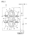
- FIG. 2 is an outline block diagram of a double-gear-type fuel pump 2 (double gear pump) according to the present embodiment.
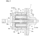
- FIG. 3 is a drawing that shows the cross-section along I-I in FIG. 2 .
- FIG. 4 is a drawing that enlarges a portion of FIG. 3 .
- the fuel pump 2 is a double gear pump as described above, and is provided with a drive gear 20 that obtains drive force by the rotary movement that is transmitted from a drive system such as the jet engine 4 (refer to FIG. 1 ) and two driven gears (first driven gear 21 and second driven gear 22) that are oppositely arranged with the drive gear 20 therebetween.
- the drive gear 20, the first driven gear 21, and the second driven gear 22 have the same gear diameter and the same number of teeth.
- An involute tooth profile can be favorably used as the tooth profile of the drive gear 20 and the driven gears 21 and 22, but a sine curve tooth profile and a trochoid curve tooth profile are also acceptable.
- the driven gears 21 and 22 are made to mesh with the drive gear 20 in respective casings 23 (23a, 23b). Then, fuel that flows from a first suction opening 24 and a second suction opening 25 into the space between the drive gear 20 and the driven gears 21 and 22 is boosted by being confined to a closed space that is formed by the driven gears 21 and 22 and the inner wall surface of the casings 23 in accordance with the rotation of the drive gear 20 and the driven gears 21 and 22, and thereafter moves to a respective first discharge opening 26 and a second discharge opening 27 to be discharged.
- the fuel pump 2 is constituted to have a first booster portion 9 composed mainly of the drive gear 20 and the first driven gear 21, and a second booster portion 10 composed mainly of the drive gear 20 and the second driven gear 22. Accordingly, the discharge amounts of the first booster portion 9 and the second booster portion 10 are the same with respect to the rotational frequency of the drive gear 20.
- a first suction line 28 and a second suction line 29 that each extend from the fuel tank 1 are connected to the first suction opening 24 and the second suction opening 25, and a first discharge line 30 and a second discharge line 31 that each extend from the fuel metering mechanism 3 (refer to FIG. 1 ) are connected to the first discharge opening 26 and the second discharge opening 27.
- a check valve 32 from the second suction line 29 to the first suction line 28 is disposed at a middle region of the second suction line 29.
- a surplus line (not illustrated in FIG. 2 ) through which passes the surplus fuel that has been discharged from the fuel metering mechanism 3 described below is connected to the first suction line 28 and the second suction line 29.
- the drive gear 20, the first driven gear 21, and the second driven gear 22 are supported in a freely rotatable manner by a first bearing 36, a second bearing 37, and a third bearing 38 that each consist of journal bearings.
- Each of the bearings 36, 37, 38 are respectively provided with bearing portions 36a, 37a, 38a that are disposed in close contact with one side surface side of each gear (the drive gear 20, the first driven gear 21, and the second driven gear 22), and bearing portions 36b, 37b, 38b that are disposed in close contact with the other side surface side of each gear.
- the bearing portions 37a, 38a, 37b, 38b that constitute the second bearing 37 and the third bearing 38 are formed with their length in the shaft direction being the same (bearing length L0).
- the bearing portions 36a and 36b that constitute the first bearing 36 are formed with their length in the shaft direction being short compared to the bearing portions 37a, 38a, 37b, 38b (bearing length L1).
- the bearing length of the first bearing 36 (the length in the shaft direction of the area that makes sliding contact with the rotating shafts of the first driven gear 21 and the second driven gear 22: L1) is shorter. For this reason, compared to the case of a conventional example in which the bearing lengths of a drive bearing, a first bearing and a second bearing are the same, the bearing loss of the first bearing 36 is reduced.
- the lengths in the shaft direction of the collars 40a and 40b are formed so that when added with the lengths in the shaft direction of the bearing portions 36a and 36b become the same as the length in the shaft direction of the bearing portions 36b, 37b, 38b. Thereby, in the same manner as the bearing portions 37a, 38a, 37b, 38b, the side surfaces in the shaft direction of the collars 40a and 40b abut the casings 23 (23a, 23b), and so the bearing portions 36a, 36b are positioned in close contact with both side surfaces of the drive gear 20.
- the inner diameters of the collars 40a and 40b are formed larger than the bearing portions 36a and 36b, while on the other hand the outer diameters thereof are the same or slightly smaller than the bearing portions 36a and 36b. Accordingly, even when the collars 40a and 40b are fitted on the drive shaft of the drive gear 20, they hardly exert an adverse effect on the rotation of the drive shaft due to friction and the like.
- the first driven gear 21 and the second driven gear 22 that engage with the drive gear 20 are arranged at symmetrical positions with respect to the drive gear 20, and also have the same gear diameter and the same number of teeth.
- reactive forces F1 and F2 that the drive gear 20 receives from the first driven gear 21 and the second driven gear 22 are the same strength.
- the directions thereof are point symmetric with respect to the drive shaft of the drive gear 20.
- fluid pressures R1 and R2 (refer to FIG. 2 ) around the first driven gear 21 and the second driven gear 22 that mesh with the drive gear 20 are also point symmetric with respect to the drive shaft, similarly to the reactive forces F1 and F2.
- the reactive forces F1 and F2 cancel out, and the loads R1 and R2 that arise from hydraulic pressure also cancel out.
- the load that acts on the first bearing 36 that supports the drive shaft of the drive gear 20 becomes smaller compared to the second bearing 37 and the third bearing 38.
- the bearing length of the first bearing 36 (the bearing portions 36a and 36b) shorter compared to the second bearing 37 and the third bearing 38 (the bearing portions 37a, 38a, 37b, and 38b).
- fuel that is stored in the fuel tank 1 is supplied to the fuel pump 2.
- the fuel is supplied to the first suction opening 24 and the second suction opening 25 of the fuel pump 2 via the first suction line 28 and the second suction line 29.
- the fuel that is supplied to the first suction opening 24 is boosted by rotation of the first driven gear 21 that rotates along with the rotation of the drive gear 20 and by being confined to a closed space that is formed by the first driven gear 21 and the inner wall surface of the casing 23, and afterward discharged from the fuel pump 2 via the first discharge opening 26.
- the fuel that is supplied to the second suction opening 25 is boosted by rotation of the second driven gear 22 that rotates along with the rotation of the drive gear 20 and by being confined to a closed space that is formed by the second driven gear 22 and the inner wall surface of the casing 23, and afterward discharged from the fuel pump 2 via the second discharge opening 27.
- the fuel of the first and second discharge openings 26 and 27 is put in a higher pressure state than the fuel of the first and second suction openings 24 and 25.
- the fuel of the first discharge opening 26 leaks to the first suction opening 24, and the fuel of the second discharge opening 27 leaks to the second suction opening 25.
- the bearing loss of the first bearing 36 is reduced in the fuel pump 2, it is possible to realize a more efficient fuel supply than before.
- the fuel that is high pressurized by the fuel pump 2 is discharged to the fuel metering mechanism 3 via the first discharge line 30 and the second discharge line 31. Then in the fuel metering mechanism 3 a portion of the fuel is discharged as a predetermined amount toward the jet engine 4, with the remainder being returned to the fuel pump 2 as a surplus portion after being depressurized.
- the fuel that has been discharged from the fuel supply system S (fuel metering mechanism 3) to the jet engine 4 is subjected to heat exchange in the fuel cooling oil cooler 7 with oil that is used in the jet engine 4, and then supplied to the combustor 5 of the jet engine 4. Then, the fuel is combusted in the engine combustor 5, and the fan 6 is driven by the energy of this combustion, leading to rotative power.
- the gear pump according to the present invention is not limited to a gear pump that is provided in this type of fuel supply system S, and is capable of being applied to all double gear pumps that boost and discharge a fluid or the like.
- FIG. 5 is a drawing that shows a modification of the bearing portions 36a and 36b.
- the description was given of the case of using the collars 40a and 40b separately from the bearing portions 36a and 36b, but is not limited thereto.
- it may be a case in which members that are the same as the collars 40a and 40b may be integrally formed with the bearing portions 36a and 36b.
- the bearing length of the first bearing 36 (the length in the shaft direction of the area that makes sliding contact with the drive shaft of the drive gear 20: L1) is shorter. For this reason, the same effect is obtained as the case of using the collars 40a and 40b that are separate from the bearing portions 36a and 36b.
- FIG. 6 is a drawing that shows a modification of the bearings 36, 37 and 38.
- the description was given of the case of the first bearing 36, the second bearing 37, and the third bearing 38 being separately formed, but is not limited thereto.
- the first bearing 36, the second bearing 37, and the third bearing 38 may be integrally formed.
- the bearing portions 36a, 37a, 38a and the bearing portions 36b, 37b, 38b may be respectively integrated so as to constitute journal bearings.
- the bearing length of the area corresponding to the first bearing 36 (the length in the shaft direction of the area that makes sliding contact with the drive shaft of the drive gear 20: L1) is shorter. For this reason, the same effect is obtained as the cases of FIG. 4 and FIG. 5 .
Landscapes
- Engineering & Computer Science (AREA)
- Mechanical Engineering (AREA)
- General Engineering & Computer Science (AREA)
- Rotary Pumps (AREA)
- Details And Applications Of Rotary Liquid Pumps (AREA)
Applications Claiming Priority (2)
| Application Number | Priority Date | Filing Date | Title |
|---|---|---|---|
| JP2006226931A JP5040214B2 (ja) | 2006-08-23 | 2006-08-23 | 三連式ギアポンプ |
| PCT/JP2007/065905 WO2008023619A1 (fr) | 2006-08-23 | 2007-08-15 | Pompe à engrenages à trois phases |
Publications (3)
| Publication Number | Publication Date |
|---|---|
| EP2055954A1 true EP2055954A1 (de) | 2009-05-06 |
| EP2055954A4 EP2055954A4 (de) | 2012-11-14 |
| EP2055954B1 EP2055954B1 (de) | 2017-12-13 |
Family
ID=39106704
Family Applications (1)
| Application Number | Title | Priority Date | Filing Date |
|---|---|---|---|
| EP07792539.4A Active EP2055954B1 (de) | 2006-08-23 | 2007-08-15 | Doppel-zahnradpumpe |
Country Status (7)
| Country | Link |
|---|---|
| US (1) | US8672657B2 (de) |
| EP (1) | EP2055954B1 (de) |
| JP (1) | JP5040214B2 (de) |
| CN (1) | CN101523053B (de) |
| CA (1) | CA2661629C (de) |
| ES (1) | ES2660409T3 (de) |
| WO (1) | WO2008023619A1 (de) |
Cited By (2)
| Publication number | Priority date | Publication date | Assignee | Title |
|---|---|---|---|---|
| WO2015134194A1 (en) * | 2014-03-07 | 2015-09-11 | Parker-Hannifin Corporation | Three-gear pump system for low viscosity fluids |
| EP3324048A4 (de) * | 2015-07-16 | 2019-03-27 | IHI Corporation | Dreifachzahnradpumpe und fluidversorgungsvorrichtung |
Families Citing this family (11)
| Publication number | Priority date | Publication date | Assignee | Title |
|---|---|---|---|---|
| US8944793B2 (en) * | 2012-06-05 | 2015-02-03 | Hamilton Sundstrand Corporation | Flow and pressure ripple reduction with advance dual gear and bearing face cut |
| JP6014530B2 (ja) * | 2013-03-27 | 2016-10-25 | 株式会社ショーワ | 船舶推進機用トリム・チルト装置 |
| JP6265008B2 (ja) * | 2014-03-31 | 2018-01-24 | 株式会社Ihi | 3連ギアポンプ及び流体供給装置 |
| CN103967782B (zh) * | 2014-05-28 | 2016-06-01 | 樊硕 | 双向三齿轮泵 |
| US9874208B2 (en) | 2015-01-21 | 2018-01-23 | Hamilton Sunstrand Corporation | Bearing faces with fluid channels for gear pumps |
| US10443597B2 (en) | 2016-01-12 | 2019-10-15 | Hamilton Sundstrand Corporation | Gears and gear pumps |
| CN107366619A (zh) * | 2016-05-13 | 2017-11-21 | 王冬 | 碎化气泡防失压齿轮油泵 |
| CN109139263A (zh) * | 2017-06-28 | 2019-01-04 | 中国航发贵阳发动机设计研究所 | 一种航空发动机的二级回油泵 |
| CN108361191A (zh) * | 2018-02-02 | 2018-08-03 | 上海发那科机器人有限公司 | 双齿轮泵系统 |
| CN109236636A (zh) * | 2018-09-12 | 2019-01-18 | 安徽江淮汽车集团股份有限公司 | 双联齿轮泵 |
| EP4567277A4 (de) | 2022-08-04 | 2026-04-22 | Ihi Corp | Dreifachgetriebepumpe |
Family Cites Families (12)
| Publication number | Priority date | Publication date | Assignee | Title |
|---|---|---|---|---|
| US2960039A (en) * | 1954-04-15 | 1960-11-15 | Phivretveit Karsten Alfred | Rotary fluid pumps and motors and the like |
| JPS542405Y1 (de) * | 1970-05-04 | 1979-02-01 | ||
| US4605363A (en) * | 1985-03-25 | 1986-08-12 | Sundstrand Corporation | Gear pump with pivoted bushings that can deflect |
| JPS6385276A (ja) * | 1986-09-29 | 1988-04-15 | Shimadzu Corp | 歯車ポンプ |
| JPH0647685U (ja) * | 1992-11-30 | 1994-06-28 | 川崎重工業株式会社 | 粘性流体用歯車ポンプの潤滑構造 |
| IT1263567B (it) * | 1993-12-07 | 1996-08-27 | O M F B Spa | Dispositivo ripartizione di flusso attivo o passivo |
| JP4065721B2 (ja) | 2002-05-14 | 2008-03-26 | 社団法人日本航空宇宙工業会 | 直列並列切り替え用ダブルギアポンプおよび切り替え回路 |
| JP4144343B2 (ja) * | 2002-12-16 | 2008-09-03 | 株式会社Ihi | 流体供給システム |
| JP2005042627A (ja) * | 2003-07-22 | 2005-02-17 | Toyoda Mach Works Ltd | 歯車ポンプ |
| JP4830311B2 (ja) | 2005-02-21 | 2011-12-07 | 株式会社デンソー | 車載用レーダ装置 |
| CN2846807Y (zh) * | 2005-09-20 | 2006-12-13 | 江苏大学 | 二级外啮合齿轮泵 |
| US7591640B2 (en) * | 2006-08-30 | 2009-09-22 | Ishikawajima-Harima Heavy Industries Co., Ltd. | Three gear type gear pump of a fuel supply system |
-
2006
- 2006-08-23 JP JP2006226931A patent/JP5040214B2/ja active Active
-
2007
- 2007-08-15 ES ES07792539.4T patent/ES2660409T3/es active Active
- 2007-08-15 US US12/438,445 patent/US8672657B2/en active Active
- 2007-08-15 CN CN2007800382254A patent/CN101523053B/zh not_active Expired - Fee Related
- 2007-08-15 CA CA2661629A patent/CA2661629C/en active Active
- 2007-08-15 WO PCT/JP2007/065905 patent/WO2008023619A1/ja not_active Ceased
- 2007-08-15 EP EP07792539.4A patent/EP2055954B1/de active Active
Cited By (3)
| Publication number | Priority date | Publication date | Assignee | Title |
|---|---|---|---|---|
| WO2015134194A1 (en) * | 2014-03-07 | 2015-09-11 | Parker-Hannifin Corporation | Three-gear pump system for low viscosity fluids |
| EP3324048A4 (de) * | 2015-07-16 | 2019-03-27 | IHI Corporation | Dreifachzahnradpumpe und fluidversorgungsvorrichtung |
| US10648467B2 (en) | 2015-07-16 | 2020-05-12 | Ihi Corporation | Triple gear pump and fluid supplying device |
Also Published As
| Publication number | Publication date |
|---|---|
| EP2055954B1 (de) | 2017-12-13 |
| WO2008023619A1 (fr) | 2008-02-28 |
| EP2055954A4 (de) | 2012-11-14 |
| JP5040214B2 (ja) | 2012-10-03 |
| ES2660409T3 (es) | 2018-03-22 |
| CN101523053B (zh) | 2011-10-12 |
| CN101523053A (zh) | 2009-09-02 |
| CA2661629A1 (en) | 2008-02-28 |
| CA2661629C (en) | 2012-04-10 |
| US20100247365A1 (en) | 2010-09-30 |
| JP2008050979A (ja) | 2008-03-06 |
| US8672657B2 (en) | 2014-03-18 |
Similar Documents
| Publication | Publication Date | Title |
|---|---|---|
| EP2055954B1 (de) | Doppel-zahnradpumpe | |
| US10208624B2 (en) | Lubrication of journal bearing during clockwise and counter-clockwise rotation | |
| US10458422B2 (en) | Turbine engine provided with a lubrication unit | |
| US7662059B2 (en) | Lubrication of windmilling journal bearings | |
| EP3022420B1 (de) | Schmierung von achslagern während deren rechts- und linksdrehung | |
| EP2700818A1 (de) | Spiralverdichter | |
| US10731747B2 (en) | Gearing device with at least one structural component that rotates with respect to a housing appliance | |
| CN111828467A (zh) | 用于飞行器涡轮机的机械减速器 | |
| GB2520140A (en) | Multi-stage Pump Having Reverse Bypass Circuit | |
| US20050232784A1 (en) | Pump assembly | |
| CN114294378A (zh) | 用于飞行器涡轮发动机的机械齿轮减速器 | |
| CN114215885A (zh) | 用于飞行器涡轮机的机械变速箱 | |
| US20170044986A1 (en) | Gear pump intended, in particular, as a high pressure fuel pump | |
| US11852079B2 (en) | Aircraft turbomachine arrangement comprising a lubrication pump driven by two oblique gears | |
| US7591640B2 (en) | Three gear type gear pump of a fuel supply system | |
| US20100059315A1 (en) | High efficiency lubrication pump | |
| JP6427430B2 (ja) | スクリュー圧縮機 | |
| US8636487B2 (en) | Dual stage pump having intermittent mid-shift load supports | |
| JP4200919B2 (ja) | ギアポンプ | |
| US20250154986A1 (en) | plain bearing for an aircraft turbomachine | |
| EP3351751A1 (de) | Kraftstoff-durchfluss-regelungsanordnung eines flugzeugtriebwerks sowie verfahren | |
| CA2558201C (en) | A three gear type gear pump of a fuel supply system | |
| US20070231179A1 (en) | Structure for preventing cavitation erosion of oil pump |
Legal Events
| Date | Code | Title | Description |
|---|---|---|---|
| PUAI | Public reference made under article 153(3) epc to a published international application that has entered the european phase |
Free format text: ORIGINAL CODE: 0009012 |
|
| 17P | Request for examination filed |
Effective date: 20090306 |
|
| AK | Designated contracting states |
Kind code of ref document: A1 Designated state(s): AT BE BG CH CY CZ DE DK EE ES FI FR GB GR HU IE IS IT LI LT LU LV MC MT NL PL PT RO SE SI SK TR |
|
| AX | Request for extension of the european patent |
Extension state: AL BA HR MK RS |
|
| DAX | Request for extension of the european patent (deleted) | ||
| A4 | Supplementary search report drawn up and despatched |
Effective date: 20121015 |
|
| RIC1 | Information provided on ipc code assigned before grant |
Ipc: F04C 2/18 20060101AFI20121009BHEP |
|
| GRAP | Despatch of communication of intention to grant a patent |
Free format text: ORIGINAL CODE: EPIDOSNIGR1 |
|
| INTG | Intention to grant announced |
Effective date: 20170707 |
|
| GRAS | Grant fee paid |
Free format text: ORIGINAL CODE: EPIDOSNIGR3 |
|
| GRAA | (expected) grant |
Free format text: ORIGINAL CODE: 0009210 |
|
| AK | Designated contracting states |
Kind code of ref document: B1 Designated state(s): AT BE BG CH CY CZ DE DK EE ES FI FR GB GR HU IE IS IT LI LT LU LV MC MT NL PL PT RO SE SI SK TR |
|
| REG | Reference to a national code |
Ref country code: GB Ref legal event code: FG4D |
|
| REG | Reference to a national code |
Ref country code: AT Ref legal event code: REF Ref document number: 954666 Country of ref document: AT Kind code of ref document: T Effective date: 20171215 Ref country code: CH Ref legal event code: EP |
|
| REG | Reference to a national code |
Ref country code: IE Ref legal event code: FG4D |
|
| REG | Reference to a national code |
Ref country code: DE Ref legal event code: R096 Ref document number: 602007053393 Country of ref document: DE |
|
| REG | Reference to a national code |
Ref country code: ES Ref legal event code: FG2A Ref document number: 2660409 Country of ref document: ES Kind code of ref document: T3 Effective date: 20180322 |
|
| REG | Reference to a national code |
Ref country code: SE Ref legal event code: TRGR |
|
| REG | Reference to a national code |
Ref country code: NL Ref legal event code: MP Effective date: 20171213 |
|
| REG | Reference to a national code |
Ref country code: LT Ref legal event code: MG4D |
|
| PG25 | Lapsed in a contracting state [announced via postgrant information from national office to epo] |
Ref country code: FI Free format text: LAPSE BECAUSE OF FAILURE TO SUBMIT A TRANSLATION OF THE DESCRIPTION OR TO PAY THE FEE WITHIN THE PRESCRIBED TIME-LIMIT Effective date: 20171213 Ref country code: LT Free format text: LAPSE BECAUSE OF FAILURE TO SUBMIT A TRANSLATION OF THE DESCRIPTION OR TO PAY THE FEE WITHIN THE PRESCRIBED TIME-LIMIT Effective date: 20171213 |
|
| REG | Reference to a national code |
Ref country code: AT Ref legal event code: MK05 Ref document number: 954666 Country of ref document: AT Kind code of ref document: T Effective date: 20171213 |
|
| PG25 | Lapsed in a contracting state [announced via postgrant information from national office to epo] |
Ref country code: GR Free format text: LAPSE BECAUSE OF FAILURE TO SUBMIT A TRANSLATION OF THE DESCRIPTION OR TO PAY THE FEE WITHIN THE PRESCRIBED TIME-LIMIT Effective date: 20180314 Ref country code: BG Free format text: LAPSE BECAUSE OF FAILURE TO SUBMIT A TRANSLATION OF THE DESCRIPTION OR TO PAY THE FEE WITHIN THE PRESCRIBED TIME-LIMIT Effective date: 20180313 Ref country code: LV Free format text: LAPSE BECAUSE OF FAILURE TO SUBMIT A TRANSLATION OF THE DESCRIPTION OR TO PAY THE FEE WITHIN THE PRESCRIBED TIME-LIMIT Effective date: 20171213 |
|
| PG25 | Lapsed in a contracting state [announced via postgrant information from national office to epo] |
Ref country code: NL Free format text: LAPSE BECAUSE OF FAILURE TO SUBMIT A TRANSLATION OF THE DESCRIPTION OR TO PAY THE FEE WITHIN THE PRESCRIBED TIME-LIMIT Effective date: 20171213 |
|
| REG | Reference to a national code |
Ref country code: FR Ref legal event code: PLFP Year of fee payment: 12 |
|
| PG25 | Lapsed in a contracting state [announced via postgrant information from national office to epo] |
Ref country code: CZ Free format text: LAPSE BECAUSE OF FAILURE TO SUBMIT A TRANSLATION OF THE DESCRIPTION OR TO PAY THE FEE WITHIN THE PRESCRIBED TIME-LIMIT Effective date: 20171213 Ref country code: EE Free format text: LAPSE BECAUSE OF FAILURE TO SUBMIT A TRANSLATION OF THE DESCRIPTION OR TO PAY THE FEE WITHIN THE PRESCRIBED TIME-LIMIT Effective date: 20171213 Ref country code: CY Free format text: LAPSE BECAUSE OF FAILURE TO SUBMIT A TRANSLATION OF THE DESCRIPTION OR TO PAY THE FEE WITHIN THE PRESCRIBED TIME-LIMIT Effective date: 20171213 Ref country code: SK Free format text: LAPSE BECAUSE OF FAILURE TO SUBMIT A TRANSLATION OF THE DESCRIPTION OR TO PAY THE FEE WITHIN THE PRESCRIBED TIME-LIMIT Effective date: 20171213 |
|
| PG25 | Lapsed in a contracting state [announced via postgrant information from national office to epo] |
Ref country code: IS Free format text: LAPSE BECAUSE OF FAILURE TO SUBMIT A TRANSLATION OF THE DESCRIPTION OR TO PAY THE FEE WITHIN THE PRESCRIBED TIME-LIMIT Effective date: 20180413 Ref country code: RO Free format text: LAPSE BECAUSE OF FAILURE TO SUBMIT A TRANSLATION OF THE DESCRIPTION OR TO PAY THE FEE WITHIN THE PRESCRIBED TIME-LIMIT Effective date: 20171213 Ref country code: AT Free format text: LAPSE BECAUSE OF FAILURE TO SUBMIT A TRANSLATION OF THE DESCRIPTION OR TO PAY THE FEE WITHIN THE PRESCRIBED TIME-LIMIT Effective date: 20171213 Ref country code: PL Free format text: LAPSE BECAUSE OF FAILURE TO SUBMIT A TRANSLATION OF THE DESCRIPTION OR TO PAY THE FEE WITHIN THE PRESCRIBED TIME-LIMIT Effective date: 20171213 |
|
| REG | Reference to a national code |
Ref country code: DE Ref legal event code: R097 Ref document number: 602007053393 Country of ref document: DE |
|
| PLBE | No opposition filed within time limit |
Free format text: ORIGINAL CODE: 0009261 |
|
| STAA | Information on the status of an ep patent application or granted ep patent |
Free format text: STATUS: NO OPPOSITION FILED WITHIN TIME LIMIT |
|
| 26N | No opposition filed |
Effective date: 20180914 |
|
| PG25 | Lapsed in a contracting state [announced via postgrant information from national office to epo] |
Ref country code: DK Free format text: LAPSE BECAUSE OF FAILURE TO SUBMIT A TRANSLATION OF THE DESCRIPTION OR TO PAY THE FEE WITHIN THE PRESCRIBED TIME-LIMIT Effective date: 20171213 |
|
| PG25 | Lapsed in a contracting state [announced via postgrant information from national office to epo] |
Ref country code: SI Free format text: LAPSE BECAUSE OF FAILURE TO SUBMIT A TRANSLATION OF THE DESCRIPTION OR TO PAY THE FEE WITHIN THE PRESCRIBED TIME-LIMIT Effective date: 20171213 |
|
| PG25 | Lapsed in a contracting state [announced via postgrant information from national office to epo] |
Ref country code: MC Free format text: LAPSE BECAUSE OF FAILURE TO SUBMIT A TRANSLATION OF THE DESCRIPTION OR TO PAY THE FEE WITHIN THE PRESCRIBED TIME-LIMIT Effective date: 20171213 |
|
| REG | Reference to a national code |
Ref country code: CH Ref legal event code: PL |
|
| PG25 | Lapsed in a contracting state [announced via postgrant information from national office to epo] |
Ref country code: LI Free format text: LAPSE BECAUSE OF NON-PAYMENT OF DUE FEES Effective date: 20180831 Ref country code: LU Free format text: LAPSE BECAUSE OF NON-PAYMENT OF DUE FEES Effective date: 20180815 Ref country code: CH Free format text: LAPSE BECAUSE OF NON-PAYMENT OF DUE FEES Effective date: 20180831 |
|
| REG | Reference to a national code |
Ref country code: BE Ref legal event code: MM Effective date: 20180831 |
|
| REG | Reference to a national code |
Ref country code: IE Ref legal event code: MM4A |
|
| PG25 | Lapsed in a contracting state [announced via postgrant information from national office to epo] |
Ref country code: IE Free format text: LAPSE BECAUSE OF NON-PAYMENT OF DUE FEES Effective date: 20180815 |
|
| PG25 | Lapsed in a contracting state [announced via postgrant information from national office to epo] |
Ref country code: BE Free format text: LAPSE BECAUSE OF NON-PAYMENT OF DUE FEES Effective date: 20180831 |
|
| PG25 | Lapsed in a contracting state [announced via postgrant information from national office to epo] |
Ref country code: MT Free format text: LAPSE BECAUSE OF NON-PAYMENT OF DUE FEES Effective date: 20180815 |
|
| PG25 | Lapsed in a contracting state [announced via postgrant information from national office to epo] |
Ref country code: TR Free format text: LAPSE BECAUSE OF FAILURE TO SUBMIT A TRANSLATION OF THE DESCRIPTION OR TO PAY THE FEE WITHIN THE PRESCRIBED TIME-LIMIT Effective date: 20171213 |
|
| PG25 | Lapsed in a contracting state [announced via postgrant information from national office to epo] |
Ref country code: PT Free format text: LAPSE BECAUSE OF FAILURE TO SUBMIT A TRANSLATION OF THE DESCRIPTION OR TO PAY THE FEE WITHIN THE PRESCRIBED TIME-LIMIT Effective date: 20171213 Ref country code: HU Free format text: LAPSE BECAUSE OF FAILURE TO SUBMIT A TRANSLATION OF THE DESCRIPTION OR TO PAY THE FEE WITHIN THE PRESCRIBED TIME-LIMIT; INVALID AB INITIO Effective date: 20070815 |
|
| PGFP | Annual fee paid to national office [announced via postgrant information from national office to epo] |
Ref country code: SE Payment date: 20220721 Year of fee payment: 16 Ref country code: ES Payment date: 20220901 Year of fee payment: 16 Ref country code: DE Payment date: 20220720 Year of fee payment: 16 |
|
| PGFP | Annual fee paid to national office [announced via postgrant information from national office to epo] |
Ref country code: FR Payment date: 20220721 Year of fee payment: 16 |
|
| REG | Reference to a national code |
Ref country code: DE Ref legal event code: R119 Ref document number: 602007053393 Country of ref document: DE |
|
| PG25 | Lapsed in a contracting state [announced via postgrant information from national office to epo] |
Ref country code: SE Free format text: LAPSE BECAUSE OF NON-PAYMENT OF DUE FEES Effective date: 20230816 |
|
| PG25 | Lapsed in a contracting state [announced via postgrant information from national office to epo] |
Ref country code: FR Free format text: LAPSE BECAUSE OF NON-PAYMENT OF DUE FEES Effective date: 20230831 Ref country code: DE Free format text: LAPSE BECAUSE OF NON-PAYMENT OF DUE FEES Effective date: 20240301 |
|
| REG | Reference to a national code |
Ref country code: ES Ref legal event code: FD2A Effective date: 20240927 |
|
| PG25 | Lapsed in a contracting state [announced via postgrant information from national office to epo] |
Ref country code: ES Free format text: LAPSE BECAUSE OF NON-PAYMENT OF DUE FEES Effective date: 20230816 |
|
| PG25 | Lapsed in a contracting state [announced via postgrant information from national office to epo] |
Ref country code: ES Free format text: LAPSE BECAUSE OF NON-PAYMENT OF DUE FEES Effective date: 20230816 |
|
| PGFP | Annual fee paid to national office [announced via postgrant information from national office to epo] |
Ref country code: IT Payment date: 20250723 Year of fee payment: 19 |
|
| PGFP | Annual fee paid to national office [announced via postgrant information from national office to epo] |
Ref country code: GB Payment date: 20250725 Year of fee payment: 19 |