EP2055959A2 - Pumpe für Motorkühlkreise mit magnetbetriebenem Flussregler - Google Patents
Pumpe für Motorkühlkreise mit magnetbetriebenem Flussregler Download PDFInfo
- Publication number
- EP2055959A2 EP2055959A2 EP08004757A EP08004757A EP2055959A2 EP 2055959 A2 EP2055959 A2 EP 2055959A2 EP 08004757 A EP08004757 A EP 08004757A EP 08004757 A EP08004757 A EP 08004757A EP 2055959 A2 EP2055959 A2 EP 2055959A2
- Authority
- EP
- European Patent Office
- Prior art keywords
- pump
- engine cooling
- cooling circuits
- chamber
- annular element
- Prior art date
- Legal status (The legal status is an assumption and is not a legal conclusion. Google has not performed a legal analysis and makes no representation as to the accuracy of the status listed.)
- Withdrawn
Links
- 238000001816 cooling Methods 0.000 title claims description 27
- 230000033001 locomotion Effects 0.000 claims abstract description 20
- 239000012809 cooling fluid Substances 0.000 claims abstract description 19
- 229910052751 metal Inorganic materials 0.000 claims description 11
- 239000002184 metal Substances 0.000 claims description 11
- 229910001172 neodymium magnet Inorganic materials 0.000 claims description 10
- 239000004033 plastic Substances 0.000 claims description 7
- 229910052779 Neodymium Inorganic materials 0.000 claims description 5
- QJVKUMXDEUEQLH-UHFFFAOYSA-N [B].[Fe].[Nd] Chemical compound [B].[Fe].[Nd] QJVKUMXDEUEQLH-UHFFFAOYSA-N 0.000 claims description 5
- QEFYFXOXNSNQGX-UHFFFAOYSA-N neodymium atom Chemical compound [Nd] QEFYFXOXNSNQGX-UHFFFAOYSA-N 0.000 claims description 5
- 239000002991 molded plastic Substances 0.000 claims description 4
- ZZUFCTLCJUWOSV-UHFFFAOYSA-N furosemide Chemical compound C1=C(Cl)C(S(=O)(=O)N)=CC(C(O)=O)=C1NCC1=CC=CO1 ZZUFCTLCJUWOSV-UHFFFAOYSA-N 0.000 claims description 2
- 238000002485 combustion reaction Methods 0.000 abstract description 5
- 239000000446 fuel Substances 0.000 abstract description 5
- 241001275902 Parabramis pekinensis Species 0.000 abstract description 2
- 239000000463 material Substances 0.000 description 9
- 238000000034 method Methods 0.000 description 5
- 239000012530 fluid Substances 0.000 description 4
- 230000000694 effects Effects 0.000 description 3
- 230000007257 malfunction Effects 0.000 description 3
- 230000006835 compression Effects 0.000 description 2
- 238000007906 compression Methods 0.000 description 2
- 230000008595 infiltration Effects 0.000 description 2
- 238000001764 infiltration Methods 0.000 description 2
- 229910000838 Al alloy Inorganic materials 0.000 description 1
- 239000004809 Teflon Substances 0.000 description 1
- 229920006362 Teflon® Polymers 0.000 description 1
- 238000004026 adhesive bonding Methods 0.000 description 1
- 238000010276 construction Methods 0.000 description 1
- 230000001419 dependent effect Effects 0.000 description 1
- 230000004927 fusion Effects 0.000 description 1
- 239000007789 gas Substances 0.000 description 1
- 230000007774 longterm Effects 0.000 description 1
- 238000012423 maintenance Methods 0.000 description 1
- 230000003068 static effect Effects 0.000 description 1
Images



Classifications
-
- F—MECHANICAL ENGINEERING; LIGHTING; HEATING; WEAPONS; BLASTING
- F04—POSITIVE - DISPLACEMENT MACHINES FOR LIQUIDS; PUMPS FOR LIQUIDS OR ELASTIC FLUIDS
- F04D—NON-POSITIVE-DISPLACEMENT PUMPS
- F04D15/00—Control, e.g. regulation, of pumps, pumping installations or systems
- F04D15/0027—Varying behaviour or the very pump
- F04D15/0038—Varying behaviour or the very pump by varying the effective cross-sectional area of flow through the rotor
-
- F—MECHANICAL ENGINEERING; LIGHTING; HEATING; WEAPONS; BLASTING
- F04—POSITIVE - DISPLACEMENT MACHINES FOR LIQUIDS; PUMPS FOR LIQUIDS OR ELASTIC FLUIDS
- F04D—NON-POSITIVE-DISPLACEMENT PUMPS
- F04D29/00—Details, component parts, or accessories
- F04D29/40—Casings; Connections of working fluid
- F04D29/42—Casings; Connections of working fluid for radial or helico-centrifugal pumps
- F04D29/44—Fluid-guiding means, e.g. diffusers
- F04D29/46—Fluid-guiding means, e.g. diffusers adjustable
- F04D29/466—Fluid-guiding means, e.g. diffusers adjustable especially adapted for liquid fluid pumps
- F04D29/468—Fluid-guiding means, e.g. diffusers adjustable especially adapted for liquid fluid pumps adjusting flow cross-section, otherwise than by using adjustable stator blades
Definitions
- This invention relates to a pump for cooling circuits provided with a magnetic-actuated flow regulator.
- this invention relates to a pump especially usable for allowing the circulation of a cooling fluid in internal combustion engines or fuel cells.
- the dissipation of excess heat is usually obtained fitting the engine or the fuel cell with a cooling fluid circulation system.
- the circulation of the aforesaid cooling fluids into the engine is obtained, in a preferred but non-limiting manner, using mechanical, electro-mechanical or magnetic drive pumps that circulate the fluid and keep the component temperature at such a value as to ensure correct and safe operation thereof.
- the mechanical pumps used for achieving the aforesaid purpose are characterised by an impeller keyed onto a shaft placed in rotation by a belt drive, pulley or the like connected to the engine.
- the impeller In magnetic drive pumps, on the contrary, the impeller is placed in rotation by means of the magnetic field induced through a series of permanent magnets arranged in coaxial direction relative to the internal body.
- the cooling fluid circulates continuously with a flow rate that is function of the number of revolutions per minute of the engine and as a consequence, the pump continues to operate even when this is not strictly necessary; for example, when the external temperature is quite low or very low, engine cooling is even counter-productive as regards optimal operation in steady conditions, control of consumptions and control of the emissions of burnt gases.
- the object of this invention is to obviate the drawback mentioned hereinabove.
- the object of this invention is to provide a pump for cooling circuits with magnetic-actuated flow regulator which allows actuating the cooling fluid circulation only when this is required by the temperature conditions reached by the engine components.
- a further object of this invention is to provide a pump as defined above of the "fail-safe" type, that is, such as to ensure correct operation of the pump itself even in the case of malfunction or fault.
- a further object of this invention is to provide the users with a magnetic drive pump for cooling circuits suitable for ensuring high level of resistance and reliability over time, which allows to be quickly and easily to assembled and also such as to be easily and inexpensively constructed.
- the pump for engine cooling circuits with magnetic-actuated flow regulator of the invention is composed of an impeller 12 known per se and keyed, by means of a bush 13 or in other known manner, to the bottom end of a rotation shaft 14, preferably with differentiated diameters.
- Said shaft is connected, through a hub 16 fixed at the top end of the rotation shaft itself and on the opposite side relative to that of fixing of the impeller 12, to a pulley (not shown in the figure) or to an equivalent means suitable for transmitting the rotary motion to the shaft.
- the rotation shaft 14 is turnably arranged relative to a container body 18, advantageously made by fusion of aluminium alloy or other suitable material and suitable for allowing the steady and safe fixing of the pump relative to the internal combustion engine or to the fuel cell.
- the rotation shaft 14 is supported in the movement thereof into the container body 18 by one or more bearings or brasses 20 arranged inside the container body 18 and coaxially to the rotation shaft 14.
- a shaped element 24 is arranged in the region comprised between the impeller 12 and the bottom front, facing the direction of the impeller itself, of the container body 18.
- Said shaped element 24 made of sheet metal or moulded plastic or other suitable material, comprises:
- the appendices of the top portion 24" of the shaped element 24 insert into the chamber 19 of the container body and preferably have an "S" shaped profile; said appendices are sliding in axial direction into the chamber 19 according to the methods described hereinafter.
- a sleeve 26 is fixed to the container body 18 at the central portion thereof and is inserted into the chamber 19 of the container body 18; said sleeve 26 has a flange or edge 26' suitable for defining a stop to the sliding, into the chamber 17, of the appendices of the top portion 24" of the shaped element 24.
- a first magnetic ring 28 made in a single piece preferably of plastic neodymium, neodymium-iron-boron (NdFeB) or other equivalent and known material is fixed, by means of a joint, by gluing or other known manner, at the top end of the shaped appendices of the top portion 24" of the shaped element 24.
- the first magnetic ring 28 may be defined by a plurality of magnetic blocks preferably inserted in a metal beam and fixed in a known manner to the top side of the appendices of the top portion 24".
- the chamber 17 is closed underside, at the bottom of the container body 18 facing the direction of the impeller 12 of the pump, by means of an annular cap 30 partly inserted into the chamber 17.
- Two or more seals 32 that define static seals, ensure the seal of the annular cap 30 and prevent the infiltration of fluid into the chamber 17 of the container body 18.
- An elastic means for example a helical spring 34, whose function will be explained hereinafter, is inserted into the chamber 17.
- the helical spring supports an annular element 36, made of metal or plastic or other known material, from whose top front facing the direction opposite the annular cap 30 at least one optional lip 38 develops in vertical direction, extending in a continuous or partial manner, along the entire circumference of the annular element 36.
- the aforesaid annular element 36 has a section basically shaped as an "H" with two grooves into each whereof one or more rings 37 are received, preferably made of Teflon, which ensure the seal and help the movement of the annular element itself into the chamber 17.
- the annular element 36 together with the lip 38 defines the support for a second magnetic ring 40 made, like the first magnetic ring 28, in a single piece and of plastic neodymium, neodymium-iron-boron (NdFeB) or other equivalent and known material.
- a second magnetic ring 40 made, like the first magnetic ring 28, in a single piece and of plastic neodymium, neodymium-iron-boron (NdFeB) or other equivalent and known material.
- the second magnetic ring 40 may be defined by a plurality of magnetic blocks, preferably inserted in a metal beam , relative to the annular element 36 and the at least one optional lip 38.
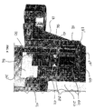
- FIGS. 4 , 5 and 6 schematically show the pump for engine cooling circuits with magnetic-actuated flow regulator of the invention according to an embodiment alternative to the preferred one said alternative embodiment is indicated by reference numeral 10'.
- the container body 18 externally and concentrically to the central part suitable for receiving the rotation shaft 14, defines two concentric chambers 17' and 19', of the annular type, extending in axial direction and open at the bottom front of the container body 18 facing the direction of the impeller 12.
- Said cylindrical body 50 is partly inserted into the chamber 17' and slidingly arranged in axial direction relative to the same according to the methods described hereinafter.
- At least a first magnetic ring 52 made, like those described before with reference to the preferred embodiment, of plastic neodymium, neodymium-iron-boron (NdFeB) or other equivalent and known material, is fixed in a known manner on the inner side surface of said cylindrical body 50 and at the top portion thereof, facing the direction of the bottom of the chamber 17'; said first magnetic ring is made in a single piece or is defined by a plurality of magnetic blocks, preferably inserted in a metal frame, fixed to the side surface of the cylindrical body 50.
- NdFeB neodymium-iron-boron
- the chamber 19' is closed underside, at the bottom of the container body 18 facing the direction of the impeller 12, by means of an annular cap 30" partly inserted into the chamber itself.
- Two or more seals 54, defining seals, ensure the seal of the annular cap 30' and prevent the infiltration of cooling fluid into the chamber 19' of the container body 18.
- an elastic means for example at least one helical spring 56, whose function shall be explained hereinafter, is inserted into the chamber 19'.
- the helical spring supports an annular element 58, made of metal or plastic or other known material, from whose top front facing the direction opposite the annular cap 30' at least one optional lip 60 develops in vertical direction, extending in a continuous or partial manner, along the entire circumference of the annular element 58.
- the aforesaid annular element 58 has the same structural features as the annular element 36 of the preferred embodiment and for this reason it is not subject of a detailed description; one or more rings 62, similar to rings 37, which ensure the seal and help the movement of the annular element itself into the chamber 19', are inserted into each of the grooves of the annular element 58.
- the annular element 58 together with the optional lip 62 defines the support for at least a second magnetic ring 64 made, like the first magnetic ring 52, in a single piece and of plastic neodymium, neodymium-iron-boron (NdFeB) or other equivalent and known material.
- a second magnetic ring 64 made, like the first magnetic ring 52, in a single piece and of plastic neodymium, neodymium-iron-boron (NdFeB) or other equivalent and known material.
- first magnetic ring 52 also the second magnetic ring 64 may be defined by a plurality of magnetic blocks, preferably inserted in a metal frame, relative to the annular element 58 and the at least one optional lip 60.
- the pump for engine cooling circuits of the invention is preferably connected to a pneumatic supply circuit (not shown in the figure) suitable for actuating, by drawing air into the chamber 17 or 19' of the container body 18, the movement according to the methods discussed hereinafter; as an alternative, the movement may also be actuated by hydraulic, mechanical or electromagnetic drives, or other known type.
- a pneumatic supply circuit (not shown in the figure) suitable for actuating, by drawing air into the chamber 17 or 19' of the container body 18, the movement according to the methods discussed hereinafter; as an alternative, the movement may also be actuated by hydraulic, mechanical or electromagnetic drives, or other known type.
- axial movement means such as for example a pneumatic supply circuit for the axial movement of the shaped element 24, or respectively of the cylindrical body 50, which by drawing air into the chamber 17 or 19' of the container body 18, actuates the axial movement of said elements, or hydraulic, mechanical, electromagnetic drives or other known type.
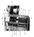
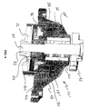
- Figure 2 shows the final "on” condition of the pump, that is, the condition wherein, with the impeller 12 in rotation, the cooling fluid circulates into the circuit.
- the bottom portion 24' of the shaped element 24 is not in contact with the volute (the body that surrounds the impeller 12 of the pump and not shown in the figure) of the pump basement; as schematised in figure 2 , the top front of the bottom element 24' is in contact with the bottom front of the annular cap 30; starting from the configuration whereof at figure 2 , the pneumatic supply circuit draws air from the chamber 17 (by means of the pneumatic supply circuit) of the container body 18 and then, the helical spring 34 is in the condition of maximum compression into the chamber 17 itself (see figure 1 ).
- the impeller 12 is actuated by means of the pulley or another motion driving means and allows the circulation of the cooling fluid.
- the downwards movement of the shaped element 24 interrupts when it contacts the volute of the pump basement.
- the bottom portion 24' of the shaped element 24 is thereby fitted onto the impeller 12 and in contact with the top front of the same.
- FIG 5 shows the "on" condition of the pump of the invention according to the alternative embodiment; the impeller 12 is already in rotation and the cooling fluid circulates into the circuit as already mentioned before.
- the pump then moves to the "off" configuration schematised in figure 4 wherein the cylindrical body 50 closes the volute of the pump base thus preventing the fluid circulation.
- the pump for engine cooling circuits of the invention by the effect of the alternating up/down movement of the shaped element 24 enables/disables the supply of cooling fluid keeping the impeller itself always in rotation.
- a further advantage is represented by the fact that varying the position of the annular element 36 and 58 into the chamber 17 and 19' it is possible to "choke" the cooling fluid supply according to the specific needs.
- a further advantage of the pump of the invention is represented by the fact that it defines a "fail- safe" device suitable for ensuring the pump operation even in conditions of malfunction or failure; in fact, with particular reference to the preferred embodiment, if the pneumatic supply fails, the helical spring 34 moves to rest condition, that is, fully extended into the chamber 17 of the container body 18 and the pump is in the "off" configuration described above and schematised at figure 2 .
- a further advantage of the pump of the invention is represented by the fact that it allows eliminating the dynamic mechanical seals that in the long term may cause breakage and malfunctions.
- a further advantage is the fact that the pump of the invention is simple and inexpensive to construct, and its components are quick and easy to replace in the case of maintenance.
Landscapes
- Engineering & Computer Science (AREA)
- Mechanical Engineering (AREA)
- General Engineering & Computer Science (AREA)
- Structures Of Non-Positive Displacement Pumps (AREA)
- Magnetically Actuated Valves (AREA)
Applications Claiming Priority (1)
| Application Number | Priority Date | Filing Date | Title |
|---|---|---|---|
| IT002078A ITMI20072078A1 (it) | 2007-10-29 | 2007-10-29 | Pompa per circuiti di raffreddamento motore con regolatore di portata ad azionamento magnetico |
Publications (2)
| Publication Number | Publication Date |
|---|---|
| EP2055959A2 true EP2055959A2 (de) | 2009-05-06 |
| EP2055959A3 EP2055959A3 (de) | 2015-09-30 |
Family
ID=40313887
Family Applications (1)
| Application Number | Title | Priority Date | Filing Date |
|---|---|---|---|
| EP08004757.4A Withdrawn EP2055959A3 (de) | 2007-10-29 | 2008-03-14 | Pumpe für Motorkühlkreise mit magnetbetriebenem Flussregler |
Country Status (2)
| Country | Link |
|---|---|
| EP (1) | EP2055959A3 (de) |
| IT (1) | ITMI20072078A1 (de) |
Cited By (1)
| Publication number | Priority date | Publication date | Assignee | Title |
|---|---|---|---|---|
| CN103277343A (zh) * | 2013-06-26 | 2013-09-04 | 长城汽车股份有限公司 | 车辆内燃机冷却系统用水泵 |
Family Cites Families (5)
| Publication number | Priority date | Publication date | Assignee | Title |
|---|---|---|---|---|
| DE9200240U1 (de) * | 1992-01-11 | 1992-02-27 | Kultscher, Armin Henry, 3300 Braunschweig | Variable Strömungsmaschine |
| DE10235721B4 (de) * | 2002-08-03 | 2006-06-29 | Geräte- und Pumpenbau GmbH Dr. Eugen Schmidt Merbelsrod | Regelbare Kühlmittelpumpe |
| DE102004054637B4 (de) * | 2004-11-12 | 2007-04-26 | Geräte- und Pumpenbau GmbH Dr. Eugen Schmidt | Regelbare Kühlmittelpumpe |
| DE102005004315B4 (de) * | 2005-01-31 | 2007-04-26 | Geräte- und Pumpenbau GmbH Dr. Eugen Schmidt | Regelbare Kühlmittelpumpe |
| JP2007138717A (ja) * | 2005-11-14 | 2007-06-07 | Aisin Seiki Co Ltd | ウォータポンプ |
-
2007
- 2007-10-29 IT IT002078A patent/ITMI20072078A1/it unknown
-
2008
- 2008-03-14 EP EP08004757.4A patent/EP2055959A3/de not_active Withdrawn
Cited By (2)
| Publication number | Priority date | Publication date | Assignee | Title |
|---|---|---|---|---|
| CN103277343A (zh) * | 2013-06-26 | 2013-09-04 | 长城汽车股份有限公司 | 车辆内燃机冷却系统用水泵 |
| CN103277343B (zh) * | 2013-06-26 | 2015-12-02 | 长城汽车股份有限公司 | 车辆内燃机冷却系统用水泵 |
Also Published As
| Publication number | Publication date |
|---|---|
| EP2055959A3 (de) | 2015-09-30 |
| ITMI20072078A1 (it) | 2009-04-30 |
Similar Documents
| Publication | Publication Date | Title |
|---|---|---|
| KR100194078B1 (ko) | 과열이 방지되는 스크롤 압축기 | |
| KR100395957B1 (ko) | 밀폐형 압축기의 오일펌핑장치 | |
| US2985358A (en) | Air pumps | |
| KR101284173B1 (ko) | 내부냉각회로를 갖춘 수중펌프 | |
| US20130081583A1 (en) | Regulatable coolant pump having integrated pressure chamber | |
| CN106795970B (zh) | 密封装置 | |
| CN108350889B (zh) | 用于内燃机的冷却剂泵 | |
| US3688140A (en) | Leakage control means for a submersible motor assembly | |
| EP2055959A2 (de) | Pumpe für Motorkühlkreise mit magnetbetriebenem Flussregler | |
| CN112524051B (zh) | 一种水润滑离心泵 | |
| CN203548202U (zh) | 容量调节涡旋式压缩机 | |
| US6102363A (en) | Actuator for reciprocating air driven devices | |
| RU2662848C2 (ru) | Ступень центробежного насоса, центробежный насос и применение ступени насоса | |
| CN1287093C (zh) | 液体泵及密封件 | |
| US3684400A (en) | Submersible pump and control system | |
| KR102702340B1 (ko) | 축진동감소부에 의해 임펠러의 회전진동을 저감한 입축 또는 수중 펌프 | |
| EP2551484B1 (de) | Pneumatisch betätigte Kühlpumpe | |
| CN108678968B (zh) | 一种带自动排气功能的水泵 | |
| CN102792029B (zh) | 机械式冷却液泵 | |
| US1960659A (en) | Pumping apparatus | |
| US4772183A (en) | High temperature oil circulating pump | |
| CN110966209B (zh) | 一种泵用电动真空泵引水系统 | |
| US2808817A (en) | Thermostatically controlled fan and coupling assembly | |
| EP2310685A1 (de) | Anlaufvorrichtung für elektrische pumpen | |
| GB2263139A (en) | Vacuum pump with pendulum action. |
Legal Events
| Date | Code | Title | Description |
|---|---|---|---|
| PUAI | Public reference made under article 153(3) epc to a published international application that has entered the european phase |
Free format text: ORIGINAL CODE: 0009012 |
|
| AK | Designated contracting states |
Kind code of ref document: A2 Designated state(s): AT BE BG CH CY CZ DE DK EE ES FI FR GB GR HR HU IE IS IT LI LT LU LV MC MT NL NO PL PT RO SE SI SK TR |
|
| AX | Request for extension of the european patent |
Extension state: AL BA MK RS |
|
| PUAL | Search report despatched |
Free format text: ORIGINAL CODE: 0009013 |
|
| AK | Designated contracting states |
Kind code of ref document: A3 Designated state(s): AT BE BG CH CY CZ DE DK EE ES FI FR GB GR HR HU IE IS IT LI LT LU LV MC MT NL NO PL PT RO SE SI SK TR |
|
| AX | Request for extension of the european patent |
Extension state: AL BA MK RS |
|
| RIC1 | Information provided on ipc code assigned before grant |
Ipc: F04D 15/00 20060101AFI20150826BHEP Ipc: F04D 29/46 20060101ALI20150826BHEP |
|
| AKX | Designation fees paid |
Designated state(s): AT BE BG CH CY CZ DE DK EE ES FI FR GB GR HR HU IE IS IT LI LT LU LV MC MT NL NO PL PT RO SE SI SK TR |
|
| AXX | Extension fees paid |
Extension state: AL Extension state: BA Extension state: MK Extension state: RS |
|
| STAA | Information on the status of an ep patent application or granted ep patent |
Free format text: STATUS: THE APPLICATION IS DEEMED TO BE WITHDRAWN |
|
| 18D | Application deemed to be withdrawn |
Effective date: 20160331 |