EP2551484B1 - Pneumatisch betätigte Kühlpumpe - Google Patents
Pneumatisch betätigte Kühlpumpe Download PDFInfo
- Publication number
- EP2551484B1 EP2551484B1 EP12005234.5A EP12005234A EP2551484B1 EP 2551484 B1 EP2551484 B1 EP 2551484B1 EP 12005234 A EP12005234 A EP 12005234A EP 2551484 B1 EP2551484 B1 EP 2551484B1
- Authority
- EP
- European Patent Office
- Prior art keywords
- annular cavity
- containment body
- ring
- respect
- axial
- Prior art date
- Legal status (The legal status is an assumption and is not a legal conclusion. Google has not performed a legal analysis and makes no representation as to the accuracy of the status listed.)
- Active
Links
Images


Classifications
-
- F—MECHANICAL ENGINEERING; LIGHTING; HEATING; WEAPONS; BLASTING
- F01—MACHINES OR ENGINES IN GENERAL; ENGINE PLANTS IN GENERAL; STEAM ENGINES
- F01P—COOLING OF MACHINES OR ENGINES IN GENERAL; COOLING OF INTERNAL-COMBUSTION ENGINES
- F01P5/00—Pumping cooling-air or liquid coolants
- F01P5/10—Pumping liquid coolant; Arrangements of coolant pumps
- F01P5/12—Pump-driving arrangements
-
- F—MECHANICAL ENGINEERING; LIGHTING; HEATING; WEAPONS; BLASTING
- F04—POSITIVE - DISPLACEMENT MACHINES FOR LIQUIDS; PUMPS FOR LIQUIDS OR ELASTIC FLUIDS
- F04D—NON-POSITIVE-DISPLACEMENT PUMPS
- F04D15/00—Control, e.g. regulation, of pumps, pumping installations or systems
- F04D15/0005—Control, e.g. regulation, of pumps, pumping installations or systems by using valves
- F04D15/0022—Control, e.g. regulation, of pumps, pumping installations or systems by using valves throttling valves or valves varying the pump inlet opening or the outlet opening
-
- F—MECHANICAL ENGINEERING; LIGHTING; HEATING; WEAPONS; BLASTING
- F04—POSITIVE - DISPLACEMENT MACHINES FOR LIQUIDS; PUMPS FOR LIQUIDS OR ELASTIC FLUIDS
- F04D—NON-POSITIVE-DISPLACEMENT PUMPS
- F04D15/00—Control, e.g. regulation, of pumps, pumping installations or systems
- F04D15/0027—Varying behaviour or the very pump
- F04D15/0038—Varying behaviour or the very pump by varying the effective cross-sectional area of flow through the rotor
-
- F—MECHANICAL ENGINEERING; LIGHTING; HEATING; WEAPONS; BLASTING
- F01—MACHINES OR ENGINES IN GENERAL; ENGINE PLANTS IN GENERAL; STEAM ENGINES
- F01P—COOLING OF MACHINES OR ENGINES IN GENERAL; COOLING OF INTERNAL-COMBUSTION ENGINES
- F01P7/00—Controlling of coolant flow
- F01P7/14—Controlling of coolant flow the coolant being liquid
- F01P2007/146—Controlling of coolant flow the coolant being liquid using valves
-
- F—MECHANICAL ENGINEERING; LIGHTING; HEATING; WEAPONS; BLASTING
- F05—INDEXING SCHEMES RELATING TO ENGINES OR PUMPS IN VARIOUS SUBCLASSES OF CLASSES F01-F04
- F05D—INDEXING SCHEME FOR ASPECTS RELATING TO NON-POSITIVE-DISPLACEMENT MACHINES OR ENGINES, GAS-TURBINES OR JET-PROPULSION PLANTS
- F05D2270/00—Control
- F05D2270/60—Control system actuates means
- F05D2270/65—Pneumatic actuators
Definitions
- the present invention refers to a pneumatically-operated cooling pump.
- the present invention refers to a cooling pump preferably used for conveying and circulating coolants, including but not limited to, inside internal combustion engines.
- the engine has a system suitable for guaranteeing the circulation of coolants such as to maintain a temperature suitable for the correct and long-lasting operation of the engine.
- the types of pumps used for the purpose are numerous and different in terms of construction characteristics and as regards the way they operate (mechanical pumps, electromechanical pumps, magnetic-drive pumps).
- Such and known types of pumps are characterised by the presence of an impeller keyed on a shaft placed in rotation by means of a belt drive, gear drive or the like (mechanical pumps) or the impeller is placed in rotation by means of a magnetic field induced through the use of permanent magnets coaxial with the rotation shaft of the impeller itself (magnetic drive pumps).
- cooling pumps have been made equipped with a device for regulating the flow rate so as to allow the circulation of the coolant only when really required by the engine.
- a cooling pump for internal combustion engines suitable for guaranteeing continuous operation (fail-safe) even in the case of unfortunate drawbacks and comprising a pump body, a rotation shaft to which an impeller is connected, an annular shutter positioned in the pump body and having a series of pins or pistons coupled with coaxial seals suitable for moving the annular shutter in the direction of the impeller to check the quantity of coolant.
- the object of the present invention is to provide a pump equipped with a device for regulating the flow rate operated pneumatically and exempt from the use of seals with sliding parts typically subject to wear and characterised by potential and unfortunate coolant leaks.
- a further object of the present invention is to place at the disposal of users a pneumatically-operated cooling pump suitable for providing a high standard of strength and reliability over time and such, furthermore, to be easily and inexpensively made.
- the pneumatically-operated cooling pump of the present invention which comprises a containment body placed above an underlying volute inside which a shutter is positioned which surrounds an impeller keyed on a rotation shaft, immersed in a fluid of water and glycol and suitable for putting said fluid in motion, the pump also comprising pneumatically-operated mechanical means with axial movement for operating the shutter and static seal means positioned to separate between the containment body and the underlying coolant and cooperating with said mechanical means for the movement of the shutter, the mechanical means and the static seals being housed in the containment body.
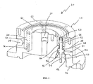
- the pneumatically-operated cooling pump of the present invention indicated by 10 in the illustrations as a whole, comprises a containment body 12 closed at the top, preferably but not only, by a lid 14 stabilized to the top front of the containment body 12 by means of screws fitted in holes 13 or by calking, gluing or equivalent known retention means.
- Said containment body 12 is stabilized with its bottom front, opposite to the top front, closed by the lid 14, to an underlying volute (not shown in the illustration) inside which a shutter is positioned which surrounds an impeller keyed on a rotation shaft (the shutter and the impeller are not shown in the illustration either); with said shutter which opens/closes the channel for the flow of cooling fluid (water and glycol) in which the impeller is immersed.
- the containment body 12 is defined, preferably but not only, by a discoid base 16 which centrally develops, in a vertical direction and substantially starting with its top front, a portion 18 centrally provided with a blind annular cavity 20 formed starting from the top front of the portion 18 itself.
- a discoid base 16 which centrally develops, in a vertical direction and substantially starting with its top front, a portion 18 centrally provided with a blind annular cavity 20 formed starting from the top front of the portion 18 itself.
- Inside said annular cavity 20 are formed, starting from the bottom of the cavity and partially developed in this in the direction of the top front of the containment body 12, at least three bodies 22, arranged angularly at 120°, provided inside with an axial chamber 24 with differentiated diameters, the function of which will be explained below; said axial chamber 24 communicates at the top with the annular cavity 20 and at the bottom with the bottom of the containment body 12.
- the annular cavity 20 circumscribes a central portion 26 of the portion 18 of the containment body 12 extended vertically in the direction of the top front 12' of the portion 18 of the mentioned containment body 12 and for a height corresponding to that of the same portion 18.
- a duct 29 is made communicating with the annular cavity 20; said duct is connected to a pneumatic supply system.
- Further ducts 31 are made along the lateral surface of the portion 18 in a radial direction and in correspondence to each body 22; said further ducts put a specific portion of the axial chamber 24 in contact with the outside and, consequently, such chamber is in atmospheric pressure conditions.
- annular cavity 20 is closed at the top by an annular seal 28, made of rubber or other known material with elastic characteristics and suitable for the purpose, wherein the flaps are in contact with the edges of the annular cavity 20.
- the annular seal 28 fits partially into the annular cavity 20 with its vertical peripheral surfaces in contact with the perimeter surfaces of the annular cavity itself.
- the section profile of the annular seal 28 has an undulated shape or "W" shape with a crest or dome 30 included between two parallel and opposite grooves 32.
- the profile of the same annular seal 28 takes on a "U" type shape with a groove 34.
- At least three possible guide pins 36 are arranged stabilized with one extremity with respect to a seat 38 formed on the bottom surface or base of the annular cavity 20.
- a possible elastic element, defined by a helical spring 40, is fitted coaxially over each guide pin 36.
- the assembly defined by the guide pin 36 and by the helical spring 40 is not present.
- the annular cavity 20 defines the housing and axial movement seat of an actuator unit comprising a ring 42, coaxial with the annular cavity 20, coupled at the top with the seal 28 inside the crest 30 (in idle conditions) and comprising at least three circular cavities or seats 43 with respect to which are connected at the bottom at least three stems 44 arranged coaxially to each body 22 and partially sliding with respect to the axial chamber 24 of the bodies themselves.
- an actuator unit comprising a ring 42, coaxial with the annular cavity 20, coupled at the top with the seal 28 inside the crest 30 (in idle conditions) and comprising at least three circular cavities or seats 43 with respect to which are connected at the bottom at least three stems 44 arranged coaxially to each body 22 and partially sliding with respect to the axial chamber 24 of the bodies themselves.
- Each stem 44 consists of a first rod 46 protruding from the axial chamber 24 in the annular cavity 20 and stabilized, in correspondence to its upper extremity, in the round cavity or seat 43 of the ring 42 by means of an elastic retention ring 45, by a truncated-cone expansion 50 with a lower smaller-diameter portion or base turned in the direction of the bottom of the axial chamber 24 and in contact with a diaphragm 52, by a second rod 54 extending starting from the smaller-diameter portion or base of the truncated-cone expansion 50 which crosses the axial chamber 24 and is connected to the shutter (not shown in the illustration).
- the diaphragm 52 is cup shaped with the outer lateral surface of the edge in correspondence to the lower open extremity of the diaphragm itself in contact with the lateral walls of the axial chamber 24; such diaphragm is blocked at the lateral surface of the axial chamber 24, in correspondence to its open extremity, by means of at least one shaped ring 53 placed in contact with the inner lateral surface of the seal 52 in correspondence to the open extremity of the seal itself, said at least one shaped ring 53 is, in turn, fastened to the lower portion of the cavity 24 by means of stop ring 61 or by other traditional and known means of retention.
- At least one further stop ring 56 placed on the bottom of the diaphragm 52 on the opposite side compared to the open extremity, ensures a stable and safe coupling between the diaphragm itself and the second rod 54 of the stem 44 of the actuator unit.
- the diaphragm 52 creates the static seal between the axial chamber 24 of the containment body 12 and the lower portion of the pump wherein water and glycol are present under pressure; said diaphragm, furthermore, cooperates with the up and down movement of the stems connected to the ring 42 of the actuator unit without this moving in any way with respect to its housing seat.
- the first rod 46 of each stem 44 is sliding with respect to a further seal 58 arranged inside the axial chamber 24 in correspondence to the upper greater-diameter portion or base of the truncated-cone expansion 50 of the stem 44 and to a bush 60 of the flanged type arranged above the further seal 58 and outside the axial chamber 24.
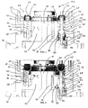
- the upper extremity of the elastic element or helical spring 40 (if fitted) is engaged in contact with the bottom front of the ring 42 of the actuator unit which, in the configuration shown in figure 1 or idle configuration, is shown fitted inside the crest 30 of the annular seal 28.
- the pump impeller In non-operating or idle conditions, when the shutter is open and does not prevent the fluid from accessing the volute, the pump impeller is in rotation, causing the circulation of the coolant inside the cooling circuit; the device of the invention is in the configuration shown in figure 1 .
- the air supply circuit takes air from the annular cavity 20 through the duct 29 creating a vacuum inside the annular cavity 20 and, consequently, the annular diaphragm 28 is deformed with the crest 30 which drops adding onto the grooves 32 and defining a single groove 34. Due to the effect of such deformation the ring 42 of the actuator unit is moved by axial sliding inside the annular cavity 20 causing the stems 44 to slide coaxially to the axial chamber 24, the truncated-cone expansion 50 of each stem 44 presses on the diaphragm 52 causing a downward deformation of the closed bottom of same, as schematized in the figure 2 .
- the elastic elements or return-action springs 40 and, consequently, the guide pins 36 are not present; the return action or axial sliding reversal of the ring 42 and of the stems 44 of the actuator unit is defined by the pressure of the liquid in the part below the containment body 12 applied on the diaphragm 52.
- the pneumatically-operated cooling pump of the invention advantageously allows separating the portion of the pump immersed in the fluid (water and glycol) and the portion immersed in air, by means of the use of static seals.
- a further advantage is the fact that the pump of the invention uses static seals defined by the diaphragms 52; these define static seals which are not subject to relative movements during the sliding of the piston, and are not therefore subject to wear by sliding and provide the pump as a whole with a longer working life, without the risk of coolant leaks occurring.
- a further advantage is represented by the fact that the pneumatically-operated pump of the invention allows enabling/disabling the supply of coolant to the circuit, while always maintaining the rotation of the pump impeller.
Landscapes
- Engineering & Computer Science (AREA)
- Mechanical Engineering (AREA)
- General Engineering & Computer Science (AREA)
- Chemical & Material Sciences (AREA)
- Combustion & Propulsion (AREA)
- Structures Of Non-Positive Displacement Pumps (AREA)
- Superconductors And Manufacturing Methods Therefor (AREA)
Claims (7)
- Pneumatisch betätigte Kühlpumpe (10), insbesondere geeignet zum Fördern und Zirkulieren von Kühlmitteln in Verbrennungsmotoren, umfassend einen Gehäusekörper (12), der oberhalb eines unten liegenden Diffusors positioniert ist, in dessen Inneren ein Schließer platziert ist, welcher einen Impeller umschließt, der auf einer Rotationswelle verkeilt ist, in einem Fluid von Wasser und Glykol getaucht ist und geeignet ist, das Fluid in Bewegung zu setzen, wobei die Pumpe pneumatisch betätigte mechanische Einrichtungen mit axialer Bewegung zur Betätigung des Schließers umfasst, die durch eine Aktuator-Einheit festgelegt ist, welche einen Ring (42) und zumindest drei Stäben (44) umfasst, die axial bezüglich des Gehäusekörpers (12) gleiten, dadurch gekennzeichnet, dass sie ferner umfasst statische Dichtungseinrichtungen, festgelegt durch geformte Diaphragmen (52), abgestützt an den Stäben (44) und dem Gehäusekörper (12), positioniert, um zwischen dem Gehäusekörper (12) und dem unten liegenden Kühlmittel zu trennen und mit der Aktuator-Einheit zur Bewegung des Schließers zusammenarbeiten.
- Kühlmittelpumpe nach dem Anspruch 1, gekennzeichnet durch die Tatsache, dass der Gehäusekörper (12) eine scheibenförmige Basis (16) umfasst, welche sich zentral in einer Vertikalrichtung und beginnend an seiner oberen Front entwickelt, einen Abschnitt (18), der zentral mit einer blinden ringförmigen Aushöhlung (20) versehen ist, die beginnend von der oberen Front (12') des Abschnitts (18) selbst ausgebildet ist, innerhalb welchem die Hohlräume (20) ausgebildet sind, beginnend von dem Boden des Hohlraums und teilweise in dieser Richtung der oberen Front des Gehäusekörpers (12) sich erstreckend, zumindest drei Körper (22), die winklig bei 120° angeordnet und innerhalb einer axialen Kammer (24) mit unterschiedlichen Durchmessern vorgesehen sind, und an der Oberseite mit dem ringförmigen Hohlraum (20) verbunden sind und an dem Boden mit dem Boden des Gehäusekörpers (12) verbunden sind, wobei die Körper (22) und axialen Kammern (24) geeignet sind, das Gehäuse für die betätigenden mechanischen Einrichtungen und für die statischen Dichtungen zu begrenzen, der Körper (18) des Gehäusekörpers (12) mit einer Durchführung (29) versehen ist, die mit dem ringförmigen Hohlraum (20) verbunden ist und mit weiteren Durchführungen (31), die mit den axialen Kammern (24) verbunden sind, wobei die Durchführung (29) und die weiteren Durchführungen (31) in radialer Richtung hergestellt und zur Verbindung des ringförmigen Hohlraums mit dem Luftzufuhrsystem und jeder axialen Kammer mit der äußeren Umgebung jeweils in Atmosphärendruckbedingungen zu verbinden.
- Kühlmittelpumpe nach dem Anspruch 2, dadurch gekennzeichnet, dass der ringförmige Hohlraum (20) des Gehäusekörpers (12) an der Oberseite durch eine ringförmige Dichtung (28) geschlossen ist, dessen umfängliche Klappen mit den Kanten des ringförmigen Hohlraums in Kontakt stehen, wobei die ringförmige Dichtung (28) teilweise in den ringförmigen Hohlraum (20) eingepasst ist, wobei ihre gegenüberliegenden vertikalen Umfangsoberflächen in Kontakt mit den Umfangsoberflächen des ringförmigen Hohlraums selbst stehen, wobei die Ringdichtung, die in Leerlaufzuständen eine gewellte Form oder eine "W"-Form mit einer Krone oder einer Kuppel (30) aufweist, die zwischen zwei parallelen und gegenüberliegenden Nuten (32) positioniert ist, und welche in Betriebszuständen eine "O"-Form mit einer Nut (34) aufweist.
- Kühlmittelpumpe nach dem Anspruch 1, dadurch gekennzeichnet, dass der Ring (42) mit dem ringförmigen Hohlraum (20) koaxial ist und an der Oberseite mit der Dichtung (28) gekoppelt ist, wobei die zumindest drei Schäfte (44) bei 120° angeordnet sind, axial bezüglich der Körper (22) gleiten, und unterhalb des Rings (42) in Entsprechung mit kreisförmigen Hohlräumen oder Sitzen (43) desselben stabilisiert sind, wobei jeder Schaft (44) einen ersten Stab (46) umfasst, der aus der axialen Kammer (24) in den ringförmigen Hohlraum (20) herausragt und dessen oberster Endpunkt bezüglich des ringförmigen Hohlraums oder Sitzes (43) des Rings (42) mittels eines elastischen Rückhalterings (45) befestigt ist, einer Kegelstumpfexpansion (50) mit einem unteren Abschnitt oder einer Basis von kleinerem Durchmesser, gedreht in die Richtung des Bodens der axialen Kammer (24), und einen zweiten Stab (54), der ausgehend von dem Abschnitt oder der Basis kleineren Durchmessers der Kegelexpansion (50) sich erstreckt, die axiale Kammer (24) kreuzt und mit dem beweglichen Element oder Schließer zum Ermöglichen/Verhindern der Zirkulation des Kühlmittels umfasst.
- Kühlmittelpumpe nach dem Anspruch 1, dadurch gekennzeichnet, dass das Diaphragma (52) becherförmig ist, wobei die äußere seitliche Oberfläche der Kante in Entsprechung mit dem unteren offenen Ende in Kontakt mit der seitlichen Oberfläche der axialen Kammer (24) steht und an dieser mittels zumindest eines geformten Rings (53) befestigt ist, der in Kontakt mit der Innenseitenoberfläche der Dichtung (52) in Entsprechung mit dem offenen Ende desselben platziert ist, wobei der zumindest eine geformte Ring (53) an dem unteren Abschnitt des axialen Hohlraums (24) mittels des Rückhalterings (61) befestigt ist, wobei die äußere Bodenoberfläche des Diaphragmas (52) in Kontakt mit dem unteren Abschnitt oder der Basis kleineren Durchmessers der Expansion (50) des Kolbens (44) steht, wobei das Diaphragma zumindest einen weiteren Rückhaltering (56) aufweist, der auf dem inneren Boden des Diaphragmas (52) auf der gegenüberliegenden Seite bezüglich der Expansion (50) platziert ist, dies koaxial mit dem zweiten Stab (54) des Kolbens (44) und geeignet zum Stabilisieren des Diaphragmas bezüglich der zweiten Stange (54) des Schafts (44) der Aktuator-Einheit.
- Kühlmittelpumpe nach dem Anspruch 4, dadurch gekennzeichnet, dass der erste Stab (46) des Schafts (44) bezüglich einer weiteren Dichtung (58) gleitet, die innerhalb der axialen Kammer (24) in Entsprechung mit dem oberen Abschnitt oder der Basis mit größerem Durchmesser der Kegelstumpfexpansion (50) des Schafts selbst und bezüglich einer Flanschbuchse (60) angeordnet ist, die oberhalb des Diaphragmas (58) und außerhalb der Axialkammer (24) auf der oberen Front oder Basis des Gehäuse (22) angeordnet ist.
- Kühlmittelpumpe nach dem Anspruch 1, dadurch gekennzeichnet, dass die pneumatisch betätigte mechanische Einrichtung zumindest drei mögliche elastische Elemente oder Schraubenfedern (40) umfasst, die alle koaxial über einen Führungsstift (36) eingepasst sind, der innerhalb des ringförmigen Hohlraums (20) in zwischenliegender Position bezüglich der Körper (22) angeordnet ist, und wobei das untere Ende stabilisiert bezüglich eines Sitzes (38), der auf dem Boden des oberen Endes des elastischen Elements oder der Schraubenfeder (40) ausgebildet ist, das bzw. die auf der Bodenfront des Rings (42) der Aktuator-Einheit ruht.
Applications Claiming Priority (1)
| Application Number | Priority Date | Filing Date | Title |
|---|---|---|---|
| IT001379A ITMI20111379A1 (it) | 2011-07-25 | 2011-07-25 | Pompa di raffreddamento ad azionamento pneumatico |
Publications (2)
| Publication Number | Publication Date |
|---|---|
| EP2551484A1 EP2551484A1 (de) | 2013-01-30 |
| EP2551484B1 true EP2551484B1 (de) | 2014-12-10 |
Family
ID=44545827
Family Applications (1)
| Application Number | Title | Priority Date | Filing Date |
|---|---|---|---|
| EP12005234.5A Active EP2551484B1 (de) | 2011-07-25 | 2012-07-13 | Pneumatisch betätigte Kühlpumpe |
Country Status (3)
| Country | Link |
|---|---|
| EP (1) | EP2551484B1 (de) |
| ES (1) | ES2531162T3 (de) |
| IT (1) | ITMI20111379A1 (de) |
Families Citing this family (1)
| Publication number | Priority date | Publication date | Assignee | Title |
|---|---|---|---|---|
| EP2902631B1 (de) | 2014-02-04 | 2018-10-24 | METELLI S.p.A. | Verstellbare Kreiselpumpe mit einer Hülse, die mittels eines Dreh-Translationssystems von geneigten Flächen betätigt wird |
Family Cites Families (3)
| Publication number | Priority date | Publication date | Assignee | Title |
|---|---|---|---|---|
| DE102005062200B3 (de) * | 2005-12-23 | 2007-02-22 | Geräte- und Pumpenbau GmbH Dr. Eugen Schmidt | Regelbare Kühlmittelpumpe |
| DE102007022189A1 (de) * | 2007-05-11 | 2008-11-27 | Geräte- und Pumpenbau GmbH Dr. Eugen Schmidt | Regelbare Kühlmittelpumpe |
| EP2299084A1 (de) * | 2009-09-16 | 2011-03-23 | Pierburg Pump Technology GmbH | Mechanische Kühlpumpe |
-
2011
- 2011-07-25 IT IT001379A patent/ITMI20111379A1/it unknown
-
2012
- 2012-07-13 EP EP12005234.5A patent/EP2551484B1/de active Active
- 2012-07-13 ES ES12005234T patent/ES2531162T3/es active Active
Also Published As
| Publication number | Publication date |
|---|---|
| ES2531162T3 (es) | 2015-03-11 |
| EP2551484A1 (de) | 2013-01-30 |
| ITMI20111379A1 (it) | 2013-01-26 |
Similar Documents
| Publication | Publication Date | Title |
|---|---|---|
| JP5368553B2 (ja) | ポンプ | |
| US7644731B2 (en) | Gas valve with resilient seat | |
| JPH04272490A (ja) | スクロール式圧縮機 | |
| KR930016671A (ko) | 배압 밸브 | |
| KR900002541B1 (ko) | 온도조절기 | |
| NO340081B1 (no) | «Kompressorsammenstilling og fremgangsmåte for operering av en ventil som styrer fluidstrøm gjennom en kompressor» | |
| JP2018537609A (ja) | 内燃機関用冷却媒体ポンプ | |
| KR101982695B1 (ko) | 조리 기구 및 이의 제어 방법 | |
| KR101303125B1 (ko) | 삼방밸브 | |
| CN110185914A (zh) | 航空发动机用滑油滤 | |
| EP2551484A1 (de) | Pneumatisch betätigte Kühlpumpe | |
| CN114109850A (zh) | 一种带回流阀的自吸泵 | |
| US20100267503A1 (en) | Hydraulic tensioning element for a traction mechanism drive | |
| JPH0245449Y2 (de) | ||
| CN113153705A (zh) | 一种具有防水透气结构的隔膜泵 | |
| CN108523641B (zh) | 用于烹饪器具的盖体和具有其的烹饪器具 | |
| JP6582538B2 (ja) | 流体圧ポンプ | |
| US20130302189A1 (en) | Centrifugal electric pump for suction of aeriform fluids with liquids anti-infiltration device | |
| KR101793791B1 (ko) | 유로 차단 기능을 구비한 감압밸브 장치 | |
| US2808817A (en) | Thermostatically controlled fan and coupling assembly | |
| KR102073110B1 (ko) | 가변 사판식 압축기용 토출체크밸브 | |
| KR101607571B1 (ko) | 다이아프램 펌프 어셈블리 | |
| CN222352592U (zh) | 膨胀阀、热泵管理系统和车辆 | |
| EP2055959A2 (de) | Pumpe für Motorkühlkreise mit magnetbetriebenem Flussregler | |
| CN108591072B (zh) | 一种用于车辆的水泵 |
Legal Events
| Date | Code | Title | Description |
|---|---|---|---|
| PUAI | Public reference made under article 153(3) epc to a published international application that has entered the european phase |
Free format text: ORIGINAL CODE: 0009012 |
|
| AK | Designated contracting states |
Kind code of ref document: A1 Designated state(s): AL AT BE BG CH CY CZ DE DK EE ES FI FR GB GR HR HU IE IS IT LI LT LU LV MC MK MT NL NO PL PT RO RS SE SI SK SM TR |
|
| AX | Request for extension of the european patent |
Extension state: BA ME |
|
| 17P | Request for examination filed |
Effective date: 20130605 |
|
| GRAP | Despatch of communication of intention to grant a patent |
Free format text: ORIGINAL CODE: EPIDOSNIGR1 |
|
| RIC1 | Information provided on ipc code assigned before grant |
Ipc: F04D 15/00 20060101ALI20140630BHEP Ipc: F01P 5/12 20060101AFI20140630BHEP |
|
| INTG | Intention to grant announced |
Effective date: 20140801 |
|
| GRAS | Grant fee paid |
Free format text: ORIGINAL CODE: EPIDOSNIGR3 |
|
| GRAA | (expected) grant |
Free format text: ORIGINAL CODE: 0009210 |
|
| AK | Designated contracting states |
Kind code of ref document: B1 Designated state(s): AL AT BE BG CH CY CZ DE DK EE ES FI FR GB GR HR HU IE IS IT LI LT LU LV MC MK MT NL NO PL PT RO RS SE SI SK SM TR |
|
| REG | Reference to a national code |
Ref country code: GB Ref legal event code: FG4D |
|
| REG | Reference to a national code |
Ref country code: CH Ref legal event code: EP |
|
| REG | Reference to a national code |
Ref country code: IE Ref legal event code: FG4D |
|
| REG | Reference to a national code |
Ref country code: AT Ref legal event code: REF Ref document number: 700783 Country of ref document: AT Kind code of ref document: T Effective date: 20150115 |
|
| REG | Reference to a national code |
Ref country code: DE Ref legal event code: R096 Ref document number: 602012004159 Country of ref document: DE Effective date: 20150122 |
|
| REG | Reference to a national code |
Ref country code: ES Ref legal event code: FG2A Ref document number: 2531162 Country of ref document: ES Kind code of ref document: T3 Effective date: 20150311 |
|
| REG | Reference to a national code |
Ref country code: AT Ref legal event code: MK05 Ref document number: 700783 Country of ref document: AT Kind code of ref document: T Effective date: 20141210 Ref country code: NL Ref legal event code: VDEP Effective date: 20141210 |
|
| REG | Reference to a national code |
Ref country code: NL Ref legal event code: VDEP Effective date: 20141210 |
|
| PG25 | Lapsed in a contracting state [announced via postgrant information from national office to epo] |
Ref country code: FI Free format text: LAPSE BECAUSE OF FAILURE TO SUBMIT A TRANSLATION OF THE DESCRIPTION OR TO PAY THE FEE WITHIN THE PRESCRIBED TIME-LIMIT Effective date: 20141210 Ref country code: LT Free format text: LAPSE BECAUSE OF FAILURE TO SUBMIT A TRANSLATION OF THE DESCRIPTION OR TO PAY THE FEE WITHIN THE PRESCRIBED TIME-LIMIT Effective date: 20141210 Ref country code: NO Free format text: LAPSE BECAUSE OF FAILURE TO SUBMIT A TRANSLATION OF THE DESCRIPTION OR TO PAY THE FEE WITHIN THE PRESCRIBED TIME-LIMIT Effective date: 20150310 |
|
| REG | Reference to a national code |
Ref country code: LT Ref legal event code: MG4D |
|
| PG25 | Lapsed in a contracting state [announced via postgrant information from national office to epo] |
Ref country code: RS Free format text: LAPSE BECAUSE OF FAILURE TO SUBMIT A TRANSLATION OF THE DESCRIPTION OR TO PAY THE FEE WITHIN THE PRESCRIBED TIME-LIMIT Effective date: 20141210 Ref country code: HR Free format text: LAPSE BECAUSE OF FAILURE TO SUBMIT A TRANSLATION OF THE DESCRIPTION OR TO PAY THE FEE WITHIN THE PRESCRIBED TIME-LIMIT Effective date: 20141210 Ref country code: LV Free format text: LAPSE BECAUSE OF FAILURE TO SUBMIT A TRANSLATION OF THE DESCRIPTION OR TO PAY THE FEE WITHIN THE PRESCRIBED TIME-LIMIT Effective date: 20141210 Ref country code: GR Free format text: LAPSE BECAUSE OF FAILURE TO SUBMIT A TRANSLATION OF THE DESCRIPTION OR TO PAY THE FEE WITHIN THE PRESCRIBED TIME-LIMIT Effective date: 20150311 Ref country code: AT Free format text: LAPSE BECAUSE OF FAILURE TO SUBMIT A TRANSLATION OF THE DESCRIPTION OR TO PAY THE FEE WITHIN THE PRESCRIBED TIME-LIMIT Effective date: 20141210 Ref country code: SE Free format text: LAPSE BECAUSE OF FAILURE TO SUBMIT A TRANSLATION OF THE DESCRIPTION OR TO PAY THE FEE WITHIN THE PRESCRIBED TIME-LIMIT Effective date: 20141210 |
|
| REG | Reference to a national code |
Ref country code: SK Ref legal event code: T3 Ref document number: E 18192 Country of ref document: SK |
|
| PG25 | Lapsed in a contracting state [announced via postgrant information from national office to epo] |
Ref country code: NL Free format text: LAPSE BECAUSE OF FAILURE TO SUBMIT A TRANSLATION OF THE DESCRIPTION OR TO PAY THE FEE WITHIN THE PRESCRIBED TIME-LIMIT Effective date: 20141210 |
|
| PG25 | Lapsed in a contracting state [announced via postgrant information from national office to epo] |
Ref country code: PT Free format text: LAPSE BECAUSE OF FAILURE TO SUBMIT A TRANSLATION OF THE DESCRIPTION OR TO PAY THE FEE WITHIN THE PRESCRIBED TIME-LIMIT Effective date: 20150410 Ref country code: EE Free format text: LAPSE BECAUSE OF FAILURE TO SUBMIT A TRANSLATION OF THE DESCRIPTION OR TO PAY THE FEE WITHIN THE PRESCRIBED TIME-LIMIT Effective date: 20141210 Ref country code: RO Free format text: LAPSE BECAUSE OF FAILURE TO SUBMIT A TRANSLATION OF THE DESCRIPTION OR TO PAY THE FEE WITHIN THE PRESCRIBED TIME-LIMIT Effective date: 20141210 |
|
| PG25 | Lapsed in a contracting state [announced via postgrant information from national office to epo] |
Ref country code: PL Free format text: LAPSE BECAUSE OF FAILURE TO SUBMIT A TRANSLATION OF THE DESCRIPTION OR TO PAY THE FEE WITHIN THE PRESCRIBED TIME-LIMIT Effective date: 20141210 Ref country code: IS Free format text: LAPSE BECAUSE OF FAILURE TO SUBMIT A TRANSLATION OF THE DESCRIPTION OR TO PAY THE FEE WITHIN THE PRESCRIBED TIME-LIMIT Effective date: 20150410 |
|
| REG | Reference to a national code |
Ref country code: DE Ref legal event code: R097 Ref document number: 602012004159 Country of ref document: DE |
|
| PLBE | No opposition filed within time limit |
Free format text: ORIGINAL CODE: 0009261 |
|
| STAA | Information on the status of an ep patent application or granted ep patent |
Free format text: STATUS: NO OPPOSITION FILED WITHIN TIME LIMIT |
|
| PG25 | Lapsed in a contracting state [announced via postgrant information from national office to epo] |
Ref country code: DK Free format text: LAPSE BECAUSE OF FAILURE TO SUBMIT A TRANSLATION OF THE DESCRIPTION OR TO PAY THE FEE WITHIN THE PRESCRIBED TIME-LIMIT Effective date: 20141210 |
|
| 26N | No opposition filed |
Effective date: 20150911 |
|
| PG25 | Lapsed in a contracting state [announced via postgrant information from national office to epo] |
Ref country code: SI Free format text: LAPSE BECAUSE OF FAILURE TO SUBMIT A TRANSLATION OF THE DESCRIPTION OR TO PAY THE FEE WITHIN THE PRESCRIBED TIME-LIMIT Effective date: 20141210 Ref country code: MC Free format text: LAPSE BECAUSE OF FAILURE TO SUBMIT A TRANSLATION OF THE DESCRIPTION OR TO PAY THE FEE WITHIN THE PRESCRIBED TIME-LIMIT Effective date: 20141210 |
|
| REG | Reference to a national code |
Ref country code: CH Ref legal event code: PL |
|
| PG25 | Lapsed in a contracting state [announced via postgrant information from national office to epo] |
Ref country code: LU Free format text: LAPSE BECAUSE OF FAILURE TO SUBMIT A TRANSLATION OF THE DESCRIPTION OR TO PAY THE FEE WITHIN THE PRESCRIBED TIME-LIMIT Effective date: 20150713 |
|
| REG | Reference to a national code |
Ref country code: IE Ref legal event code: MM4A |
|
| PG25 | Lapsed in a contracting state [announced via postgrant information from national office to epo] |
Ref country code: LI Free format text: LAPSE BECAUSE OF NON-PAYMENT OF DUE FEES Effective date: 20150731 Ref country code: CH Free format text: LAPSE BECAUSE OF NON-PAYMENT OF DUE FEES Effective date: 20150731 |
|
| PG25 | Lapsed in a contracting state [announced via postgrant information from national office to epo] |
Ref country code: BE Free format text: LAPSE BECAUSE OF FAILURE TO SUBMIT A TRANSLATION OF THE DESCRIPTION OR TO PAY THE FEE WITHIN THE PRESCRIBED TIME-LIMIT Effective date: 20141210 |
|
| PG25 | Lapsed in a contracting state [announced via postgrant information from national office to epo] |
Ref country code: IE Free format text: LAPSE BECAUSE OF NON-PAYMENT OF DUE FEES Effective date: 20150713 |
|
| REG | Reference to a national code |
Ref country code: FR Ref legal event code: PLFP Year of fee payment: 5 |
|
| GBPC | Gb: european patent ceased through non-payment of renewal fee |
Effective date: 20160713 |
|
| PG25 | Lapsed in a contracting state [announced via postgrant information from national office to epo] |
Ref country code: MT Free format text: LAPSE BECAUSE OF FAILURE TO SUBMIT A TRANSLATION OF THE DESCRIPTION OR TO PAY THE FEE WITHIN THE PRESCRIBED TIME-LIMIT Effective date: 20141210 |
|
| PG25 | Lapsed in a contracting state [announced via postgrant information from national office to epo] |
Ref country code: HU Free format text: LAPSE BECAUSE OF FAILURE TO SUBMIT A TRANSLATION OF THE DESCRIPTION OR TO PAY THE FEE WITHIN THE PRESCRIBED TIME-LIMIT; INVALID AB INITIO Effective date: 20120713 Ref country code: BG Free format text: LAPSE BECAUSE OF FAILURE TO SUBMIT A TRANSLATION OF THE DESCRIPTION OR TO PAY THE FEE WITHIN THE PRESCRIBED TIME-LIMIT Effective date: 20141210 Ref country code: GB Free format text: LAPSE BECAUSE OF NON-PAYMENT OF DUE FEES Effective date: 20160713 Ref country code: SM Free format text: LAPSE BECAUSE OF FAILURE TO SUBMIT A TRANSLATION OF THE DESCRIPTION OR TO PAY THE FEE WITHIN THE PRESCRIBED TIME-LIMIT Effective date: 20141210 |
|
| PG25 | Lapsed in a contracting state [announced via postgrant information from national office to epo] |
Ref country code: CY Free format text: LAPSE BECAUSE OF FAILURE TO SUBMIT A TRANSLATION OF THE DESCRIPTION OR TO PAY THE FEE WITHIN THE PRESCRIBED TIME-LIMIT Effective date: 20141210 |
|
| REG | Reference to a national code |
Ref country code: FR Ref legal event code: PLFP Year of fee payment: 6 |
|
| PG25 | Lapsed in a contracting state [announced via postgrant information from national office to epo] |
Ref country code: TR Free format text: LAPSE BECAUSE OF FAILURE TO SUBMIT A TRANSLATION OF THE DESCRIPTION OR TO PAY THE FEE WITHIN THE PRESCRIBED TIME-LIMIT Effective date: 20141210 |
|
| PG25 | Lapsed in a contracting state [announced via postgrant information from national office to epo] |
Ref country code: MK Free format text: LAPSE BECAUSE OF FAILURE TO SUBMIT A TRANSLATION OF THE DESCRIPTION OR TO PAY THE FEE WITHIN THE PRESCRIBED TIME-LIMIT Effective date: 20141210 |
|
| REG | Reference to a national code |
Ref country code: FR Ref legal event code: PLFP Year of fee payment: 7 |
|
| PG25 | Lapsed in a contracting state [announced via postgrant information from national office to epo] |
Ref country code: AL Free format text: LAPSE BECAUSE OF FAILURE TO SUBMIT A TRANSLATION OF THE DESCRIPTION OR TO PAY THE FEE WITHIN THE PRESCRIBED TIME-LIMIT Effective date: 20141210 |
|
| P01 | Opt-out of the competence of the unified patent court (upc) registered |
Effective date: 20230526 |
|
| PGFP | Annual fee paid to national office [announced via postgrant information from national office to epo] |
Ref country code: ES Payment date: 20250806 Year of fee payment: 14 |
|
| PGFP | Annual fee paid to national office [announced via postgrant information from national office to epo] |
Ref country code: DE Payment date: 20250725 Year of fee payment: 14 |
|
| PGFP | Annual fee paid to national office [announced via postgrant information from national office to epo] |
Ref country code: IT Payment date: 20250725 Year of fee payment: 14 |
|
| PGFP | Annual fee paid to national office [announced via postgrant information from national office to epo] |
Ref country code: FR Payment date: 20250724 Year of fee payment: 14 |
|
| PGFP | Annual fee paid to national office [announced via postgrant information from national office to epo] |
Ref country code: CZ Payment date: 20250704 Year of fee payment: 14 |
|
| PGFP | Annual fee paid to national office [announced via postgrant information from national office to epo] |
Ref country code: SK Payment date: 20250703 Year of fee payment: 14 |