EP2056030A2 - Buse de libération d'air pour une installation de jet séparateur - Google Patents
Buse de libération d'air pour une installation de jet séparateur Download PDFInfo
- Publication number
- EP2056030A2 EP2056030A2 EP08167790A EP08167790A EP2056030A2 EP 2056030 A2 EP2056030 A2 EP 2056030A2 EP 08167790 A EP08167790 A EP 08167790A EP 08167790 A EP08167790 A EP 08167790A EP 2056030 A2 EP2056030 A2 EP 2056030A2
- Authority
- EP
- European Patent Office
- Prior art keywords
- nozzle
- diameter
- channel
- opening
- nozzle channel
- Prior art date
- Legal status (The legal status is an assumption and is not a legal conclusion. Google has not performed a legal analysis and makes no representation as to the accuracy of the status listed.)
- Withdrawn
Links
- 230000001133 acceleration Effects 0.000 claims abstract description 11
- 238000013461 design Methods 0.000 claims description 10
- 238000005422 blasting Methods 0.000 claims description 3
- 239000010410 layer Substances 0.000 claims 2
- 238000007789 sealing Methods 0.000 claims 2
- 239000012790 adhesive layer Substances 0.000 claims 1
- 238000000926 separation method Methods 0.000 description 6
- 238000012546 transfer Methods 0.000 description 2
- 230000006978 adaptation Effects 0.000 description 1
- 238000004026 adhesive bonding Methods 0.000 description 1
- XAGFODPZIPBFFR-UHFFFAOYSA-N aluminium Chemical compound [Al] XAGFODPZIPBFFR-UHFFFAOYSA-N 0.000 description 1
- 229910052782 aluminium Inorganic materials 0.000 description 1
- 230000015572 biosynthetic process Effects 0.000 description 1
- 238000011161 development Methods 0.000 description 1
- 230000000694 effects Effects 0.000 description 1
- 239000003344 environmental pollutant Substances 0.000 description 1
- 230000002349 favourable effect Effects 0.000 description 1
- 238000007373 indentation Methods 0.000 description 1
- 238000009434 installation Methods 0.000 description 1
- 238000012423 maintenance Methods 0.000 description 1
- 238000012986 modification Methods 0.000 description 1
- 230000004048 modification Effects 0.000 description 1
- 238000005192 partition Methods 0.000 description 1
- 231100000719 pollutant Toxicity 0.000 description 1
- 230000001681 protective effect Effects 0.000 description 1
- 238000007493 shaping process Methods 0.000 description 1
- 238000000638 solvent extraction Methods 0.000 description 1
- 230000006641 stabilisation Effects 0.000 description 1
- 238000011105 stabilization Methods 0.000 description 1
Images


Classifications
-
- F—MECHANICAL ENGINEERING; LIGHTING; HEATING; WEAPONS; BLASTING
- F24—HEATING; RANGES; VENTILATING
- F24F—AIR-CONDITIONING; AIR-HUMIDIFICATION; VENTILATION; USE OF AIR CURRENTS FOR SCREENING
- F24F9/00—Use of air currents for screening, e.g. air curtains
-
- F—MECHANICAL ENGINEERING; LIGHTING; HEATING; WEAPONS; BLASTING
- F24—HEATING; RANGES; VENTILATING
- F24F—AIR-CONDITIONING; AIR-HUMIDIFICATION; VENTILATION; USE OF AIR CURRENTS FOR SCREENING
- F24F13/00—Details common to, or for air-conditioning, air-humidification, ventilation or use of air currents for screening
- F24F13/02—Ducting arrangements
- F24F13/06—Outlets for directing or distributing air into rooms or spaces, e.g. ceiling air diffuser
Definitions
- the invention relates to an air outlet nozzle for a separation jet system, which comprises a plurality of such air outlet nozzles, which can be combined to form a nozzle train with which a sharply focused air flow can be generated, which allows air space to separate space areas, such that a against weather influences protective area even at relatively high wind speeds "against the weather" - be partitioned, whether for the purpose of preventing heat exchange between the area to be protected and an outdoor area, or to prevent airborne pollutants or unwanted moisture from entering the protected area, in the z.
- the object of the invention is therefore to provide a Lucasauslassdüse of the aforementioned type, which is equally suitable for the formation of a sharply focused air flow with high volume flow as well as with only moderate noise.
- This object is achieved in connection with a design that enables a strand arrangement of a plurality of air outlet nozzles in a simple manner according to the invention by a nozzle type, wherein the distance a of the two sides of the central longitudinal axis of the nozzle channel containing central plane of the nozzle block extending broader longitudinal surfaces of the generally cuboid Nozzle block, with which this - in the strand arrangement of the nozzle - abuts the respective adjacent nozzle blocks, is significantly smaller than the clear diameter D of the inlet opening of the acceleration section of the nozzle, however, significantly larger than the clear diameter d of the cylindrical outlet section of the nozzle channel, the vertical extends to the end face of the nozzle block, in which the mouth plane of the nozzle is located.
- a plurality of nozzles to a crowded nozzle strand can be combined by the nozzle body are arranged adjacent to each other with congruent longitudinal surfaces of their nozzle blocks and secured together in a suitable manner are, so that in total, the outer shape of a formed by the nozzle body formed bar with rectangular cross-section, which is penetrated by a plurality of nozzle channels, wherein the cross-sections of the cylindrical-tubular outlet sections are closed circularly bounded, while round portions of the opening edges of the inlet openings in each case extend only over sector areas, the arcade shaped on both sides of a common center plane of the nozzle blocks, which contains the central longitudinal axes of the nozzle channels adjoin each other, each with facing each other tips, which in turn connected by parabolic or hyperbola-like edges in the first approximation are, which run in the plant levels, in which adjacent nozzle body with their wider longitudinal surfaces abut each other.
- the inlet regions of the nozzles tapering in a funnel shape toward the tubular outlet section of the nozzle channel are in communicating connection with each other, this does not cause undesirable crossflow, but only utilizes the usable inlet cross section of the nozzles most effectively, so that As a result, the high air flow rate of a slot nozzle can be combined with the properties of the tubular nozzle outlet which are favorable for jet stabilization, and nevertheless a low-noise operation of an air curtain system equipped with air outlet nozzles according to the invention is achieved with a high air throughput.
- the air outlet nozzles according to the invention can be realized in a variety of designs in a simple manner.
- each with a total of 10 Luftauslassdüse is for use in air curtain systems 11, as by the Fig. 1 A and 1 b illustrated, thought, which is used for air-technical separation of an interior of a merely schematically indicated hall 12 against the exterior of the hall building.
- Fig. 1 A and 1 b illustrated, thought, which is used for air-technical separation of an interior of a merely schematically indicated hall 12 against the exterior of the hall building.
- nozzle arrangements are used which give the most concentrated, far-reaching veiling air flow, which can develop a similar effect to a partition wall between adjacent spatial areas.
- air outlet nozzles 10 which, seen in itself, have a long throw characteristic, d. H. generate an air jet, which experiences a relatively small expansion with increasing distance from the nozzle outlet opening.
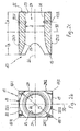
- the nozzle 10 has a block-shaped nozzle body, which has the basic shape of a cuboid whose - four - longitudinal edges 18/1, 18/2, 18/3 and 18/4 extend between the end faces 19 and 21, in which the edges of the nozzle openings 22 and 23 extend, between which extends the generally designated 24, continuous nozzle channel whose central longitudinal axis 26 is identical to the central longitudinal axis of the nozzle 10 in total.
- the nozzle channel 24 has at the air inlet side of the nozzle 10 from the inlet opening 22 from inwardly continuously tapering, funnel-shaped acceleration section 29, within which the "clear" cross section of the nozzle channel of a diameter D of the inlet opening 22 corresponding maximum value to the the smaller diameter d of the outlet opening 23 tapers corresponding amount of the cross section of the cylindrical-rohrfiörmigen outlet portion 31 of the nozzle channel.
- the acceleration section 29 and the outlet section 31 close in the central region of the nozzle block 17, as shown in FIG Fig. 2c approximately in the transverse center plane 32 of the nozzle block smoothly to each other.
- the nozzle body 17 is, as far explained, both to the longitudinal center plane 33 which extends between the wider longitudinal boundary surfaces 28/1 and 28/2 of the nozzle block, as well as to the longitudinal center plane 34 which is parallel to the narrower longitudinal boundary surfaces 27/1 and 27 / 2 of the block-shaped nozzle body 17 extends symmetrically.
- nozzle strands 40/1 and 40/2 arranged, each having a "vertical" row of about seventy nozzles 10, the in an aligned arrangement of their vertically extending narrow transverse edges and with direct contact of the wider longitudinal surfaces 28/1 and 28/2 are arranged one above the other.
- the central planes 41/1 and 41/2 containing the central longitudinal axes 26 of the individual nozzles 10 are each set at an angle of approximately 30 ° relative to the gate plane 42, so that the airflows which can be generated by means of the nozzle strands 40/1 and 40/2 can be produced.
- Fog or air separating beams meet at an angle of 120 °, so that outside the gate 13, a prismatic space is created, which is as it were separated from the wider environment.
- the air flow which is forced back under the wind pressure in the direction of the building, is calculated according to a valid "fist" rule so that per square meter opening area and m / s wind speed creates a separation air flow of about 2000 m 3 / h becomes.
- threaded bores 43/1 and 43/2 are (at bores 17 on exit-side corner regions of the nozzle blocks on the nozzle blocks ( Fig. 2c ), which allow mounting on support bars or profiles.
- nozzle bodies are adhesively secured together by gluing their abutting surfaces together and at the same time sealed.
- the supply of two nozzle strands 40/1 and 40/2 can take place via a transfer duct (46) interconnecting only the schematically indicated connection channels 44/1 and 44/2 of the nozzle strands, which in turn is connected to the air source.
- the compressed air channels 44/1 and 44/2 tapered as seen from the transfer channel to the farther nozzles out to achieve a constant Ausblastik in operation over the entire length of the strands away.
Landscapes
- Engineering & Computer Science (AREA)
- Chemical & Material Sciences (AREA)
- Combustion & Propulsion (AREA)
- Mechanical Engineering (AREA)
- General Engineering & Computer Science (AREA)
- Nozzles (AREA)
- Duct Arrangements (AREA)
- Separating Particles In Gases By Inertia (AREA)
Applications Claiming Priority (1)
| Application Number | Priority Date | Filing Date | Title |
|---|---|---|---|
| DE102007052205.5A DE102007052205B4 (de) | 2007-10-30 | 2007-10-30 | Luftauslassdüse für eine Trennstrahlanlage und Düsenstrang |
Publications (2)
| Publication Number | Publication Date |
|---|---|
| EP2056030A2 true EP2056030A2 (fr) | 2009-05-06 |
| EP2056030A3 EP2056030A3 (fr) | 2010-12-29 |
Family
ID=40279836
Family Applications (1)
| Application Number | Title | Priority Date | Filing Date |
|---|---|---|---|
| EP08167790A Withdrawn EP2056030A3 (fr) | 2007-10-30 | 2008-10-29 | Buse de libération d'air pour une installation de jet séparateur |
Country Status (2)
| Country | Link |
|---|---|
| EP (1) | EP2056030A3 (fr) |
| DE (1) | DE102007052205B4 (fr) |
Citations (1)
| Publication number | Priority date | Publication date | Assignee | Title |
|---|---|---|---|---|
| DE4415079A1 (de) | 1994-04-29 | 1995-11-02 | Teddington Controls Gmbh | Kompakt-Luftschleieranlage |
Family Cites Families (4)
| Publication number | Priority date | Publication date | Assignee | Title |
|---|---|---|---|---|
| DE3124876C2 (de) * | 1981-06-25 | 1985-09-19 | Schako Metallwarenfabrik Ferdinand Schad Kg, 7201 Kolbingen | Weitwurfdüse |
| DE8901258U1 (de) * | 1989-02-04 | 1989-06-15 | "Schako" Metallwarenfabrik Ferdinand Schad KG Zweigniederlassung Kolbingen, 7201 Kolbingen | Vorrichtung zum Be- und ggfs. auch Entlüften eines Raumes |
| US7074123B2 (en) * | 2004-01-13 | 2006-07-11 | Power Of 4, L.L.C. | Cabinet for computer devices with air distribution device |
| NL1029849C2 (nl) * | 2005-09-01 | 2007-03-05 | Biddle B V | Luchtgordijn met modulaire behuizing. |
-
2007
- 2007-10-30 DE DE102007052205.5A patent/DE102007052205B4/de not_active Expired - Fee Related
-
2008
- 2008-10-29 EP EP08167790A patent/EP2056030A3/fr not_active Withdrawn
Patent Citations (1)
| Publication number | Priority date | Publication date | Assignee | Title |
|---|---|---|---|---|
| DE4415079A1 (de) | 1994-04-29 | 1995-11-02 | Teddington Controls Gmbh | Kompakt-Luftschleieranlage |
Also Published As
| Publication number | Publication date |
|---|---|
| DE102007052205B4 (de) | 2022-01-27 |
| EP2056030A3 (fr) | 2010-12-29 |
| DE102007052205A1 (de) | 2009-05-07 |
Similar Documents
| Publication | Publication Date | Title |
|---|---|---|
| DE2706437C2 (de) | Vorrichtung zum Verbinden von wenigstens zwei, vorzugsweise aus Hohlprofilen gebildeten Rahmenteilen mittels eines Verbindungselementes | |
| EP2366082B1 (fr) | Bouche d'aération dotée d'un boîtier et plafond flottant doté d'une bouche d'aération | |
| EP3543622B1 (fr) | Dispositif d'isolation sonore et système de ventilation doté d'un tel dispositif d'isolation sonore | |
| EP4092345A1 (fr) | Silencieux à monter dans un canal d'air | |
| EP2910682B1 (fr) | Structure d'isolation acoustique plane | |
| DE69300349T2 (de) | Schalldämpfende Lüftungsvorrichtung mit einem länglichen blockförmigen Gehäuse und einem spaltförmigen Lüftungskanal. | |
| EP0563509A2 (fr) | Sortie d'air pour installation de traitement d'air | |
| EP2056030A2 (fr) | Buse de libération d'air pour une installation de jet séparateur | |
| EP2273638A2 (fr) | Pince pour canaux de câble destinée à masquer des bords de coupe | |
| DE3241424C2 (de) | Verbindungseinrichtung | |
| DE2614559A1 (de) | Doppelbodenplatte mit luft-durchtrittsoeffnungen | |
| DE9306657U1 (de) | Hängefördereinrichtung mit einem Montageprofilsatz | |
| DE19529311C1 (de) | Auslaßdüsenleiste und Verfahren zum räumlichen Verteilen eines strömenden Mediums | |
| DE2802696C2 (fr) | ||
| DE19626884A1 (de) | Luftauslaß | |
| DE19841567C1 (de) | Lüftungskanal mit Schalldämpfungselement | |
| DE2701845C3 (de) | Vorrichtung zur Bildung eines Luftvorhanges an Portalen | |
| EP3587943A2 (fr) | Dispositif d'aération et de mise en température d'une pièce dans un bâtiment | |
| DE2442378A1 (de) | Klimaanlage | |
| DE102024122909A1 (de) | Lüftungseinrichtung | |
| DE19912567A1 (de) | Luftleiteinrichtung für einen Luftdurchlaß | |
| DE102016124949B4 (de) | Adaptervorrichtung für ein Schiebetürsystem sowie Schiebetürsystem | |
| EP3097338B1 (fr) | Boîtier pour moniteur de plafond | |
| EP1347147B1 (fr) | Profilé de volet roulant | |
| EP3253459B1 (fr) | Mur avec installation de protection contre les incendies |
Legal Events
| Date | Code | Title | Description |
|---|---|---|---|
| PUAI | Public reference made under article 153(3) epc to a published international application that has entered the european phase |
Free format text: ORIGINAL CODE: 0009012 |
|
| AK | Designated contracting states |
Kind code of ref document: A2 Designated state(s): AT BE BG CH CY CZ DE DK EE ES FI FR GB GR HR HU IE IS IT LI LT LU LV MC MT NL NO PL PT RO SE SI SK TR |
|
| AX | Request for extension of the european patent |
Extension state: AL BA MK RS |
|
| PUAL | Search report despatched |
Free format text: ORIGINAL CODE: 0009013 |
|
| AK | Designated contracting states |
Kind code of ref document: A3 Designated state(s): AT BE BG CH CY CZ DE DK EE ES FI FR GB GR HR HU IE IS IT LI LT LU LV MC MT NL NO PL PT RO SE SI SK TR |
|
| AX | Request for extension of the european patent |
Extension state: AL BA MK RS |
|
| AKY | No designation fees paid | ||
| REG | Reference to a national code |
Ref country code: DE Ref legal event code: R108 |
|
| REG | Reference to a national code |
Ref country code: DE Ref legal event code: R108 Effective date: 20110907 |
|
| STAA | Information on the status of an ep patent application or granted ep patent |
Free format text: STATUS: THE APPLICATION IS DEEMED TO BE WITHDRAWN |
|
| 18D | Application deemed to be withdrawn |
Effective date: 20110630 |