EP2056048A1 - Magnetisch gekoppelte Gebläseschaufeln und Motor für einen Lebensmittelschrank - Google Patents
Magnetisch gekoppelte Gebläseschaufeln und Motor für einen Lebensmittelschrank Download PDFInfo
- Publication number
- EP2056048A1 EP2056048A1 EP08167488A EP08167488A EP2056048A1 EP 2056048 A1 EP2056048 A1 EP 2056048A1 EP 08167488 A EP08167488 A EP 08167488A EP 08167488 A EP08167488 A EP 08167488A EP 2056048 A1 EP2056048 A1 EP 2056048A1
- Authority
- EP
- European Patent Office
- Prior art keywords
- impeller
- food
- magnets
- rotor
- motor
- Prior art date
- Legal status (The legal status is an assumption and is not a legal conclusion. Google has not performed a legal analysis and makes no representation as to the accuracy of the status listed.)
- Withdrawn
Links
- 235000013305 food Nutrition 0.000 title claims abstract description 56
- 238000001816 cooling Methods 0.000 claims abstract description 44
- 238000009423 ventilation Methods 0.000 claims description 21
- 238000005057 refrigeration Methods 0.000 claims description 12
- 235000013409 condiments Nutrition 0.000 claims description 11
- 239000007788 liquid Substances 0.000 claims description 11
- 230000008878 coupling Effects 0.000 claims description 6
- 238000010168 coupling process Methods 0.000 claims description 6
- 238000005859 coupling reaction Methods 0.000 claims description 6
- 239000000463 material Substances 0.000 claims description 5
- 238000002360 preparation method Methods 0.000 claims description 5
- 229910001220 stainless steel Inorganic materials 0.000 claims description 3
- 239000010935 stainless steel Substances 0.000 claims description 3
- 238000004140 cleaning Methods 0.000 claims 1
- 239000012530 fluid Substances 0.000 abstract description 4
- 230000000295 complement effect Effects 0.000 abstract 1
- 238000005406 washing Methods 0.000 description 5
- 238000007789 sealing Methods 0.000 description 4
- 238000000034 method Methods 0.000 description 3
- 230000004888 barrier function Effects 0.000 description 2
- 239000000356 contaminant Substances 0.000 description 2
- 235000014102 seafood Nutrition 0.000 description 2
- XUIMIQQOPSSXEZ-UHFFFAOYSA-N Silicon Chemical compound [Si] XUIMIQQOPSSXEZ-UHFFFAOYSA-N 0.000 description 1
- 230000000903 blocking effect Effects 0.000 description 1
- 238000010276 construction Methods 0.000 description 1
- 238000011109 contamination Methods 0.000 description 1
- 230000000694 effects Effects 0.000 description 1
- 239000011521 glass Substances 0.000 description 1
- 230000003993 interaction Effects 0.000 description 1
- 238000004519 manufacturing process Methods 0.000 description 1
- 239000002184 metal Substances 0.000 description 1
- 229910052755 nonmetal Inorganic materials 0.000 description 1
- 229910052710 silicon Inorganic materials 0.000 description 1
- 239000010703 silicon Substances 0.000 description 1
Images


Classifications
-
- A—HUMAN NECESSITIES
- A47—FURNITURE; DOMESTIC ARTICLES OR APPLIANCES; COFFEE MILLS; SPICE MILLS; SUCTION CLEANERS IN GENERAL
- A47F—SPECIAL FURNITURE, FITTINGS, OR ACCESSORIES FOR SHOPS, STOREHOUSES, BARS, RESTAURANTS OR THE LIKE; PAYING COUNTERS
- A47F3/00—Show cases or show cabinets
- A47F3/04—Show cases or show cabinets air-conditioned, refrigerated
- A47F3/0439—Cases or cabinets of the open type
- A47F3/0443—Cases or cabinets of the open type with forced air circulation
-
- F—MECHANICAL ENGINEERING; LIGHTING; HEATING; WEAPONS; BLASTING
- F25—REFRIGERATION OR COOLING; COMBINED HEATING AND REFRIGERATION SYSTEMS; HEAT PUMP SYSTEMS; MANUFACTURE OR STORAGE OF ICE; LIQUEFACTION SOLIDIFICATION OF GASES
- F25D—REFRIGERATORS; COLD ROOMS; ICE-BOXES; COOLING OR FREEZING APPARATUS NOT OTHERWISE PROVIDED FOR
- F25D17/00—Arrangements for circulating cooling fluids; Arrangements for circulating gas, e.g. air, within refrigerated spaces
- F25D17/04—Arrangements for circulating cooling fluids; Arrangements for circulating gas, e.g. air, within refrigerated spaces for circulating air, e.g. by convection
- F25D17/06—Arrangements for circulating cooling fluids; Arrangements for circulating gas, e.g. air, within refrigerated spaces for circulating air, e.g. by convection by forced circulation
-
- F—MECHANICAL ENGINEERING; LIGHTING; HEATING; WEAPONS; BLASTING
- F25—REFRIGERATION OR COOLING; COMBINED HEATING AND REFRIGERATION SYSTEMS; HEAT PUMP SYSTEMS; MANUFACTURE OR STORAGE OF ICE; LIQUEFACTION SOLIDIFICATION OF GASES
- F25D—REFRIGERATORS; COLD ROOMS; ICE-BOXES; COOLING OR FREEZING APPARATUS NOT OTHERWISE PROVIDED FOR
- F25D17/00—Arrangements for circulating cooling fluids; Arrangements for circulating gas, e.g. air, within refrigerated spaces
- F25D17/04—Arrangements for circulating cooling fluids; Arrangements for circulating gas, e.g. air, within refrigerated spaces for circulating air, e.g. by convection
- F25D17/06—Arrangements for circulating cooling fluids; Arrangements for circulating gas, e.g. air, within refrigerated spaces for circulating air, e.g. by convection by forced circulation
- F25D17/08—Arrangements for circulating cooling fluids; Arrangements for circulating gas, e.g. air, within refrigerated spaces for circulating air, e.g. by convection by forced circulation using ducts
-
- F—MECHANICAL ENGINEERING; LIGHTING; HEATING; WEAPONS; BLASTING
- F25—REFRIGERATION OR COOLING; COMBINED HEATING AND REFRIGERATION SYSTEMS; HEAT PUMP SYSTEMS; MANUFACTURE OR STORAGE OF ICE; LIQUEFACTION SOLIDIFICATION OF GASES
- F25D—REFRIGERATORS; COLD ROOMS; ICE-BOXES; COOLING OR FREEZING APPARATUS NOT OTHERWISE PROVIDED FOR
- F25D23/00—General constructional features
- F25D23/02—Doors; Covers
- F25D23/023—Air curtain closures
-
- F—MECHANICAL ENGINEERING; LIGHTING; HEATING; WEAPONS; BLASTING
- F25—REFRIGERATION OR COOLING; COMBINED HEATING AND REFRIGERATION SYSTEMS; HEAT PUMP SYSTEMS; MANUFACTURE OR STORAGE OF ICE; LIQUEFACTION SOLIDIFICATION OF GASES
- F25D—REFRIGERATORS; COLD ROOMS; ICE-BOXES; COOLING OR FREEZING APPARATUS NOT OTHERWISE PROVIDED FOR
- F25D2317/00—Details or arrangements for circulating cooling fluids; Details or arrangements for circulating gas, e.g. air, within refrigerated spaces, not provided for in other groups of this subclass
- F25D2317/06—Details or arrangements for circulating cooling fluids; Details or arrangements for circulating gas, e.g. air, within refrigerated spaces, not provided for in other groups of this subclass with forced air circulation
- F25D2317/068—Details or arrangements for circulating cooling fluids; Details or arrangements for circulating gas, e.g. air, within refrigerated spaces, not provided for in other groups of this subclass with forced air circulation characterised by the fans
- F25D2317/0681—Details thereof
Definitions
- the application relates to a food refrigeration system, more specifically to a system for cooling food containers associated with commercial food cabinets.
- a fan is part of a cooling system to cool the removable pans of a food cabinet such as a presentation cabinet or preparation table.
- the fan impeller is mounted on a stationary shaft in the same environment as the food pans, while the electric motor that powers the fan is mounted outside of the operative environment, separated from the fan impeller and the food pans by a sealed, water-tight barrier.
- the motor is coupled with the impeller by means of magnets mounted on one or both of the fan and the rotor of the motor. Because there is no direct mechanical connection between the motor and the impeller, the need for some type of moving seal through an opening of the internal housing wall is eliminated. The risk of a liquid contacting the motor from a food spill or during washing is greatly reduced.
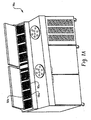
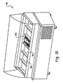
- Figs. 1A and 1B show two examples of food cabinets with removable pans.
- Fig. 2 shows a pan cooling system for a food cabinet.
- Figs. 3A and 3B show two views of an impeller for a cooling system fan assembly.
- Figs. 4A and 4B show two views of a drive motor for a cooling system fan assembly.
- Fig. 5 shows a cooling system fan assembly
- Fig. 6 shows an exploded view of a cooling system fan assembly.
- Fig. 7 shows the assembly of Fig. 6 mounted to a sealed surface.
- Fig. 8 shows a cross-section view of a self-sealing screw mounting a shaft to a sealed surface.
- Fig. 1A shows a food preparation table 70a including condiment pans 50a.
- the table 70a provides ready access to a user, which may be an employee or a customer at a food establishment.
- the food preparation table 70a allows for quick access to small quantities of condiment 52a for preparing individual servings of food.
- the cabinet 70a may be present in a room temperature environment for several hours.
- the condiment pan 50a stores a condiment 52a, which needs to be kept at a temperature substantially below room temperature in order to stay fresh.
- Fig. 1B shows a food presentation station 70b including removable pans 50b.
- the station 70b displays fresh seafood 52b which must also be kept at a low temperature in order to stay fresh. Because the presentation station 70b displays fresh seafood 52b to customers, it must be washed frequently to avoid the possibility of developing an unpleasant odor.
- Fig. 2 shows an embodiment of a cooling system appropriate to a food cabinet 70, of which both the food preparation table 70a and the food presentation station 70b are embodiments.
- a food pan 50 sits within a cooling frame 60, which itself sits within the insulated cabinet 70.
- the food pan 50 is easily removable, and several identically shaped food pans may be provided for easy replacement.
- This configuration divides the cooling environment 4 into an open environment 7 above the food pan 50, an inner ventilation chamber 8 between the food pan 50 and the cooling frame 60, and an outer ventilation chamber 9 between the cooling frame 60 and the cabinet 70.
- the cooling frame 60 includes a set of vertical air grills 62, 63, and 64.
- the cooling frame 60 also includes a horizontal air grill 65.
- the cooling frame 60 comprises separate sections 60a and 60b, the upper section 60a primarily vertical in construction and including the vertical air grills 62, 63, and 64 while the bottom section 60b is primarily horizontal and includes the horizontal air grill 65.
- the bottom section 60b may be independently removable from the cabinet 70 (such as for accessing the fan impeller 10) while leaving the upper section 60a in place.
- the cooling frame 60 may be a single unified component including both vertical and horizontal grill sections.
- a fan impeller 10 draws air from the inner ventilation chamber 8 into the outer ventilation chamber 9 and impels the air toward the evaporator coil 72 which is located in a vertical section of the outer ventilation chamber 9.
- Air passes the evaporator coil 72 and exits the outer ventilation chamber 9 through one of the vertical air grills 62, 63, and 64.
- One of these air grills 62 leads to the open environment 7 above the food pan 50; the other two air grills 63 and 64 lead to the inner ventilation chamber 8 directly below the food pan 50. Passing over the evaporator coil 72 cools the air which subsequently passes through the vertical grills, so that when this air comes in contact with the food pan 50 it acts to reduce the temperature of the food pan 50.
- Liquids may enter the outer ventilation chamber 9, either from food spills or during a washing procedure.
- the impeller 10 and stationary shaft 20 are not vulnerable to damage from casual contact with liquids, and the impeller 10 may be easily removed during washing of the upper area of the cabinet.
- contact with liquids may damage the electric drive motor 30 that drives the impeller 10 if the liquids are able to reach those components.
- the surface 2 separating the rotor 40 from the impeller 10 also works to isolate the motor 30 from the cooling environment 4 without blocking the magnetic coupling between the rotor 40 and impeller 10.
- food falling proximate to the impeller 10 during operation does not contact the motor 30, and wash liquid directed to washing the cabinet 70 also does not contact the motor 30.
- Fig. 3 shows the fan impeller 10.
- Four fan blades 12 are evenly positioned about the central body 14.
- a hole 16 to receive the stationary fan shaft 20 (shown in Fig. 5 ).
- the magnets 18 are positioned a similar distance from the center of the body 14 and are spaced evenly.
- the number of magnets 18 may vary. In one embodiment, an even number of magnets 18 are used. If an even number of magnets 18 are mounted on the central body 14, the magnets 18 may be aligned in an alternating fashion such that the poles of adjacent magnets are opposite each other, thus reducing a potential source of error in manufacturing. If the four magnets 18 are accidentally placed backwards into the impeller 10, there is no practical effect, as the same number and relative position of the magnets 18 is preserved. It has also been found that the magnetic coupling between the impeller 10 and the rotor 30 is stronger in the case of alternating opposite poles than if all the poles of the magnets 18 are facing the same direction.
- Fig. 4 shows an electric drive motor 30, which includes a rotor 40.
- the rotor contains magnets 48, which are spaced evenly in a circular configuration identical to that of the impeller magnets 18.
- the rotor magnets 48 should be configured in both spacing and polarity to couple with the impeller magnets 18. As shown in Figs. 3 and 4 , if the impeller magnets 18 are alternating in polarity, the rotor magnets 48 should do likewise.
- the fan impeller 10 when the fan is assembled, the fan impeller 10 is mounted on the stationary fan shaft 20.
- the fan impeller 10 is configured to rotate freely when mounted on the shaft 20.
- the stationary fan shaft 20 is secured to the sealed surface 2, which separates the cooling environment 4 from the motor environment 6.
- the surface 2 may be made up of multiple contiguous surfaces or may be a single unbroken surface, but the surface 2 is sealed such that likely contaminants (e.g., fluids) which exist within the cooling environment 4 cannot pass the surface 2 into the motor environment 6.
- the sealed surface 2 could be made of any material that will not interfere with the magnetic coupling of the fan assembly - for example, a nonmagnetic metal, or a nonmetal such as plastic or glass.
- the sealed surface is made of stainless steel.
- the stationary fan shaft 20 may be attached to the sealed surface by mechanical means.
- the fan shaft 20 may protrude through the sealed surface 2. Because the fan shaft 20 is stationary and does not have to mechanically impart rotation from the motor 30, an effective seal can still be produced at the surface 2 even if the shaft 20 extends completely through the surface 2 as shown in Fig. 5 .
- the fan assembly including the impeller 10, shaft 20, and motor 30 with rotor 40 are all physically connected to the surface 2 through the use of an attachment plate 22.
- the shaft 20 may be bolted to the surface independently of the motor 40, may be glued or otherwise directly attached to the surface 2, or may be built integrally with the surface 2.
- the shaft 20 may be secured to the surface 2 by any method that allows the surface 2 to maintain its seal.
- the drive motor 30 is positioned on the other side of the sealed surface 2 in the motor environment 6, where it is not subject to contact with contaminants from the cooling environment 4.
- the drive motor 30 is positioned as shown such that the rotor 40 is aligned with the central body 14 of the impeller 10.
- the magnets 18 of the impeller 10 are aligned with the magnets 48 of the rotor 40 such that the rotor 40 and central body 14 are magnetically coupled.
- the motor 30 is activated to rotate the rotor 40, the magnetically coupled impeller 10 also rotates, including the fan blades 12. Rotation of the fan impeller 10 acts to circulate air within the cooling environment 4.
- FIG. 6 Another embodiment of a cooling assembly is shown in an exploded view as Fig. 6 .
- the impeller 10' is securely attached to a hub 14' which includes four magnets 18'.
- the hub 14' is mounted on a stationary shaft 20'.
- the stationary shaft 20' includes a wide base that abuts the sealed surface 2 (shown in Fig. 7 ) to provide additional stability for the fan assembly.
- the shaft 20' is secured to the sealed surface 2 by means of a screw member 24.
- the screw member 24 is a self-sealing screw, such as a screw with a silicon o-ring under the screw head available from McMaster-Carr.
- the screw member 24 fastens the shaft 20' tightly to the sealed surface 2.
- the screw 24 and shaft 20' are stationary relative to the sealed surface 2, which allows the sealed surface 2 to maintain an effective seal around the shaft 20'.
- the motor 30' with the rotor 40' is attached to the sealed surface independently of the impeller 10' and hub 14' on the shaft 20'.
- the motor 30' is connected to a motor mount plate 80.
- a set of four hex standoffs 82 attach the plate 80 to the sealed surface.
- Both the motor 30' and standoffs 82 are fastened to the motor mount plate 80 using nuts 84.
- the standoffs 82 are attached to the sealed surface by means of screws 26, which may be self-sealing screws substantially identical to the screw member 24 described above.
- the motor 30' drives the rotor 40', which is positioned close to the sealed surface and is magnetically coupled by interaction of the rotor magnets 48' and the hub magnets 18'.
- the top surface of the rotor 40' includes a central recess of sufficient depth such that the rotor 40', which rotates rapidly during operation of the cooling system, does not come into physical contact with the head of the screw member 24, which remains stationary during cooling.
- Fig. 7 shows an elevation view of the cooling system as shown in Fig. 6 , assembled and mounted upon the sealed surface 2.
- the shaft 20', the central hub 14', and the impeller 10' are above the surface 2 within the cooling environment 4.
- the motor 30', rotor 40', and motor mount plate 80 with standoffs 82 are below the surface 2 within the motor environment 6. These two part groups do not form a mechanical connection; most notably the head of the screw member 24 does not contact the rotor 40' but rather is located within the recess in the rotor 40'.
- the motor mount plate 80 attached to the motor 40' does not rotate, and the shaft 20' also does not rotate.
- the rotor 30', central hub 14', and impeller 10' rotate together due to the magnetic coupling.
- Fig. 8 is a cross-section view of the stationary shaft 20' and self-sealing screw member 24, which includes an o-ring 25.
- the o-ring 25 presses upward tightly to maintain a seal and prevent fluids in the cooling environment 4 from entering the motor environment 6.
Landscapes
- Engineering & Computer Science (AREA)
- Physics & Mathematics (AREA)
- Thermal Sciences (AREA)
- Chemical & Material Sciences (AREA)
- Combustion & Propulsion (AREA)
- Mechanical Engineering (AREA)
- General Engineering & Computer Science (AREA)
- Cold Air Circulating Systems And Constructional Details In Refrigerators (AREA)
- Structures Of Non-Positive Displacement Pumps (AREA)
- Devices That Are Associated With Refrigeration Equipment (AREA)
Applications Claiming Priority (2)
| Application Number | Priority Date | Filing Date | Title |
|---|---|---|---|
| US98422207P | 2007-10-31 | 2007-10-31 | |
| US12/202,756 US20090107168A1 (en) | 2007-10-31 | 2008-09-02 | Magnetically coupled fan blade and motor for a food cabinet |
Publications (1)
| Publication Number | Publication Date |
|---|---|
| EP2056048A1 true EP2056048A1 (de) | 2009-05-06 |
Family
ID=40276125
Family Applications (1)
| Application Number | Title | Priority Date | Filing Date |
|---|---|---|---|
| EP08167488A Withdrawn EP2056048A1 (de) | 2007-10-31 | 2008-10-24 | Magnetisch gekoppelte Gebläseschaufeln und Motor für einen Lebensmittelschrank |
Country Status (4)
| Country | Link |
|---|---|
| US (1) | US20090107168A1 (de) |
| EP (1) | EP2056048A1 (de) |
| AU (1) | AU2008237605B2 (de) |
| CA (1) | CA2641858C (de) |
Cited By (2)
| Publication number | Priority date | Publication date | Assignee | Title |
|---|---|---|---|---|
| CH704019A3 (de) * | 2012-02-22 | 2012-06-29 | V Zug Ag | Haushaltgerät, insbesondere Kühlschrank, mit einem Ventilator im Nutzraum. |
| WO2014180692A1 (en) * | 2013-05-10 | 2014-11-13 | Arcelik Anonim Sirketi | A refrigerator comprising a storage compartment |
Families Citing this family (4)
| Publication number | Priority date | Publication date | Assignee | Title |
|---|---|---|---|---|
| US8985104B2 (en) | 2010-05-19 | 2015-03-24 | Carefusion 207, Inc. | Fan assembly for a rebreathe system |
| US20190187794A1 (en) * | 2017-12-20 | 2019-06-20 | Immersion Corporation | Systems and Methods for Pneumatic Pressure Haptic Controllers |
| CN112344620B (zh) * | 2020-11-06 | 2022-03-15 | 长虹美菱股份有限公司 | 一种具有水果冰沙专区的冰箱及其控制方法 |
| DE102023114290A1 (de) | 2023-05-05 | 2024-11-07 | Liebherr-Hausgeräte Ochsenhausen GmbH | Kühl- und/oder Gefriergerät |
Citations (6)
| Publication number | Priority date | Publication date | Assignee | Title |
|---|---|---|---|---|
| US4592209A (en) * | 1984-05-23 | 1986-06-03 | Costan S.P.A. | Display counter for food products, refrigerated by forced ventilation |
| US4802340A (en) * | 1987-10-28 | 1989-02-07 | Hobart Corporation | Refrigerated salad bar |
| US5168719A (en) * | 1991-12-24 | 1992-12-08 | Specialty Equipment Companies, Inc. | Food preparation table with open air food storage |
| DE4343537A1 (de) * | 1992-12-15 | 1994-06-16 | Reijo Maentyoja | Kühlmöbel |
| JP2000299964A (ja) * | 1999-04-09 | 2000-10-24 | Nippon Densan Corp | 回転機 |
| EP1092876A2 (de) * | 1998-11-05 | 2001-04-18 | Kabushiki Kaisha Toshiba | Lüfter für Kühlschrank |
Family Cites Families (14)
| Publication number | Priority date | Publication date | Assignee | Title |
|---|---|---|---|---|
| US2350534A (en) * | 1942-10-05 | 1944-06-06 | Rosinger Arthur | Magnetic stirrer |
| US2669851A (en) * | 1952-02-23 | 1954-02-23 | Gen Motors Corp | Open top display case with slidable hood |
| IT969511B (it) * | 1972-07-13 | 1974-04-10 | Olivetti & Co Spa | Dispositivo per lo sviluppo a spaz zola magnetica di immagini elettro statiche latenti |
| US4162855A (en) * | 1974-11-18 | 1979-07-31 | Spectroderm International, Inc. | Magnetic stirrer apparatus |
| US4019339A (en) * | 1975-08-20 | 1977-04-26 | Anderson William G | System and cold cabinet server |
| US5078504A (en) * | 1989-02-06 | 1992-01-07 | Spectrum Sciences B.V. | Dispersion apparatus |
| DE4339328C1 (de) * | 1993-11-19 | 1995-02-23 | Janke & Kunkel Kg | Verfahren und Vorrichtung zum Erkennen der Viskositätsänderung eines mittels Magnetrührer gerührten Mediums |
| US5927092A (en) * | 1995-02-03 | 1999-07-27 | Kairak, Inc. | Food pan refrigeration unit |
| US6109051A (en) * | 1998-05-15 | 2000-08-29 | Manitowoc Foodservice Group, Inc. | Food preparation table with air blast chiller |
| FR2784522B1 (fr) * | 1998-10-07 | 2001-01-05 | Cogema | Dispositif d'agitation de liquide a accouplement magnetique |
| US6416215B1 (en) * | 1999-12-14 | 2002-07-09 | University Of Kentucky Research Foundation | Pumping or mixing system using a levitating magnetic element |
| US6332706B1 (en) * | 2000-04-18 | 2001-12-25 | Wine Swirl, Llc | Method for aerating wine |
| WO2002096761A2 (en) * | 2001-05-22 | 2002-12-05 | Shurflo Pump Manufacturing Company, Inc. | Appliance and an appliance drive unit |
| DE502005005690D1 (de) * | 2004-03-16 | 2008-11-27 | Emb Papst St Georgen Gmbh & Co | Anordnung mit einem elektronisch kommutierten aussenläufermotor |
-
2008
- 2008-09-02 US US12/202,756 patent/US20090107168A1/en not_active Abandoned
- 2008-10-24 CA CA2641858A patent/CA2641858C/en not_active Expired - Fee Related
- 2008-10-24 EP EP08167488A patent/EP2056048A1/de not_active Withdrawn
- 2008-10-30 AU AU2008237605A patent/AU2008237605B2/en not_active Ceased
Patent Citations (6)
| Publication number | Priority date | Publication date | Assignee | Title |
|---|---|---|---|---|
| US4592209A (en) * | 1984-05-23 | 1986-06-03 | Costan S.P.A. | Display counter for food products, refrigerated by forced ventilation |
| US4802340A (en) * | 1987-10-28 | 1989-02-07 | Hobart Corporation | Refrigerated salad bar |
| US5168719A (en) * | 1991-12-24 | 1992-12-08 | Specialty Equipment Companies, Inc. | Food preparation table with open air food storage |
| DE4343537A1 (de) * | 1992-12-15 | 1994-06-16 | Reijo Maentyoja | Kühlmöbel |
| EP1092876A2 (de) * | 1998-11-05 | 2001-04-18 | Kabushiki Kaisha Toshiba | Lüfter für Kühlschrank |
| JP2000299964A (ja) * | 1999-04-09 | 2000-10-24 | Nippon Densan Corp | 回転機 |
Cited By (3)
| Publication number | Priority date | Publication date | Assignee | Title |
|---|---|---|---|---|
| CH704019A3 (de) * | 2012-02-22 | 2012-06-29 | V Zug Ag | Haushaltgerät, insbesondere Kühlschrank, mit einem Ventilator im Nutzraum. |
| EP2631573A3 (de) * | 2012-02-22 | 2015-07-08 | V-Zug AG | Haushaltgerät, insbesondere Kühlschrank, mit einem Ventilator im Innenraum |
| WO2014180692A1 (en) * | 2013-05-10 | 2014-11-13 | Arcelik Anonim Sirketi | A refrigerator comprising a storage compartment |
Also Published As
| Publication number | Publication date |
|---|---|
| US20090107168A1 (en) | 2009-04-30 |
| AU2008237605A1 (en) | 2009-05-14 |
| CA2641858A1 (en) | 2009-04-30 |
| CA2641858C (en) | 2011-04-26 |
| AU2008237605B2 (en) | 2009-12-24 |
Similar Documents
| Publication | Publication Date | Title |
|---|---|---|
| CA2641858C (en) | Magnetically coupled fan blade and motor for a food cabinet | |
| US11419434B1 (en) | Display case door with door handle camera | |
| US11711904B2 (en) | Apparatus for cooling electronic circuitry | |
| US20150308172A1 (en) | Door System For Airflow Control | |
| CN101160078A (zh) | 模块化制冷盒 | |
| SE1550502A1 (en) | A monitoring and controlling system for a product holding arrangement and a product holding arrangement with such a system | |
| US4603557A (en) | Refrigerated-goods display case | |
| US20060207280A1 (en) | Bottom deck assembly for refrigerated merchandiser | |
| KR20070114204A (ko) | 증발기 팬/모터 조립체 지지 브래킷 | |
| JP3242259B2 (ja) | 電装箱構造 | |
| US20050204765A1 (en) | Evaporator assembly for cold tables and method for refrigerating cold tables | |
| KR101834657B1 (ko) | 저온 더치커피 추출장치 | |
| US11493265B2 (en) | Refrigerated food pan cooling device | |
| JPS63263373A (ja) | 断熱箱体 | |
| CN101422308A (zh) | 一种用于食品柜的磁耦合的风机叶片和马达 | |
| JP4270532B2 (ja) | 平型オープンショーケース | |
| AU2017100278A4 (en) | A refrigeration cassette and refrigerator unit | |
| ATE365010T1 (de) | Kühltheke | |
| CN214631810U (zh) | 一种食品清洗机 | |
| JP2003121049A (ja) | 冷却貯蔵庫 | |
| TR2022019725A2 (tr) | Bi̇r soğutucu | |
| TR2022016130Y (tr) | Bi̇r soğutucu | |
| JP2004271077A (ja) | 対面式低温ショーケース | |
| EP1828696A1 (de) | Temperaturkühler zum schnellen kühlen und/oder schnellen gefrieren von bei niedriger temperatur zu lagernden produkten zur anwendung im haushalt | |
| JPS63217178A (ja) | 冷気循環式平形オ−プンシヨ−ケ−ス |
Legal Events
| Date | Code | Title | Description |
|---|---|---|---|
| PUAI | Public reference made under article 153(3) epc to a published international application that has entered the european phase |
Free format text: ORIGINAL CODE: 0009012 |
|
| 17P | Request for examination filed |
Effective date: 20081024 |
|
| AK | Designated contracting states |
Kind code of ref document: A1 Designated state(s): AT BE BG CH CY CZ DE DK EE ES FI FR GB GR HR HU IE IS IT LI LT LU LV MC MT NL NO PL PT RO SE SI SK TR |
|
| AX | Request for extension of the european patent |
Extension state: AL BA MK RS |
|
| 17Q | First examination report despatched |
Effective date: 20090618 |
|
| AKX | Designation fees paid |
Designated state(s): AT BE BG CH CY CZ DE DK EE ES FI FR GB GR HR HU IE IS IT LI LT LU LV MC MT NL NO PL PT RO SE SI SK TR |
|
| GRAP | Despatch of communication of intention to grant a patent |
Free format text: ORIGINAL CODE: EPIDOSNIGR1 |
|
| STAA | Information on the status of an ep patent application or granted ep patent |
Free format text: STATUS: THE APPLICATION IS DEEMED TO BE WITHDRAWN |
|
| 18D | Application deemed to be withdrawn |
Effective date: 20101221 |