EP2056082A2 - Vor Umwelteinflüssen geschützter Thermistor für ein Beatmungssystem - Google Patents
Vor Umwelteinflüssen geschützter Thermistor für ein Beatmungssystem Download PDFInfo
- Publication number
- EP2056082A2 EP2056082A2 EP08167316A EP08167316A EP2056082A2 EP 2056082 A2 EP2056082 A2 EP 2056082A2 EP 08167316 A EP08167316 A EP 08167316A EP 08167316 A EP08167316 A EP 08167316A EP 2056082 A2 EP2056082 A2 EP 2056082A2
- Authority
- EP
- European Patent Office
- Prior art keywords
- thermistor
- container
- temperature probe
- temperature
- epoxy
- Prior art date
- Legal status (The legal status is an assumption and is not a legal conclusion. Google has not performed a legal analysis and makes no representation as to the accuracy of the status listed.)
- Withdrawn
Links
Images


Classifications
-
- G—PHYSICS
- G01—MEASURING; TESTING
- G01K—MEASURING TEMPERATURE; MEASURING QUANTITY OF HEAT; THERMALLY-SENSITIVE ELEMENTS NOT OTHERWISE PROVIDED FOR
- G01K13/00—Thermometers specially adapted for specific purposes
- G01K13/20—Clinical contact thermometers for use with humans or animals
- G01K13/25—Protective devices therefor, e.g. sleeves preventing contamination
-
- A—HUMAN NECESSITIES
- A61—MEDICAL OR VETERINARY SCIENCE; HYGIENE
- A61M—DEVICES FOR INTRODUCING MEDIA INTO, OR ONTO, THE BODY; DEVICES FOR TRANSDUCING BODY MEDIA OR FOR TAKING MEDIA FROM THE BODY; DEVICES FOR PRODUCING OR ENDING SLEEP OR STUPOR
- A61M16/00—Devices for influencing the respiratory system of patients by gas treatment, e.g. ventilators; Tracheal tubes
- A61M16/021—Devices for influencing the respiratory system of patients by gas treatment, e.g. ventilators; Tracheal tubes operated by electrical means
- A61M16/022—Control means therefor
- A61M16/024—Control means therefor including calculation means, e.g. using a processor
- A61M16/026—Control means therefor including calculation means, e.g. using a processor specially adapted for predicting, e.g. for determining an information representative of a flow limitation during a ventilation cycle by using a root square technique or a regression analysis
-
- A—HUMAN NECESSITIES
- A61—MEDICAL OR VETERINARY SCIENCE; HYGIENE
- A61M—DEVICES FOR INTRODUCING MEDIA INTO, OR ONTO, THE BODY; DEVICES FOR TRANSDUCING BODY MEDIA OR FOR TAKING MEDIA FROM THE BODY; DEVICES FOR PRODUCING OR ENDING SLEEP OR STUPOR
- A61M16/00—Devices for influencing the respiratory system of patients by gas treatment, e.g. ventilators; Tracheal tubes
- A61M16/08—Bellows; Connecting tubes ; Water traps; Patient circuits
- A61M16/0816—Joints or connectors
- A61M16/0841—Joints or connectors for sampling
-
- A—HUMAN NECESSITIES
- A61—MEDICAL OR VETERINARY SCIENCE; HYGIENE
- A61M—DEVICES FOR INTRODUCING MEDIA INTO, OR ONTO, THE BODY; DEVICES FOR TRANSDUCING BODY MEDIA OR FOR TAKING MEDIA FROM THE BODY; DEVICES FOR PRODUCING OR ENDING SLEEP OR STUPOR
- A61M16/00—Devices for influencing the respiratory system of patients by gas treatment, e.g. ventilators; Tracheal tubes
- A61M16/10—Preparation of respiratory gases or vapours
- A61M16/1075—Preparation of respiratory gases or vapours by influencing the temperature
- A61M16/109—Preparation of respiratory gases or vapours by influencing the temperature the humidifying liquid or the beneficial agent
-
- A—HUMAN NECESSITIES
- A61—MEDICAL OR VETERINARY SCIENCE; HYGIENE
- A61M—DEVICES FOR INTRODUCING MEDIA INTO, OR ONTO, THE BODY; DEVICES FOR TRANSDUCING BODY MEDIA OR FOR TAKING MEDIA FROM THE BODY; DEVICES FOR PRODUCING OR ENDING SLEEP OR STUPOR
- A61M16/00—Devices for influencing the respiratory system of patients by gas treatment, e.g. ventilators; Tracheal tubes
- A61M16/10—Preparation of respiratory gases or vapours
- A61M16/1075—Preparation of respiratory gases or vapours by influencing the temperature
- A61M16/1095—Preparation of respiratory gases or vapours by influencing the temperature in the connecting tubes
-
- A—HUMAN NECESSITIES
- A61—MEDICAL OR VETERINARY SCIENCE; HYGIENE
- A61M—DEVICES FOR INTRODUCING MEDIA INTO, OR ONTO, THE BODY; DEVICES FOR TRANSDUCING BODY MEDIA OR FOR TAKING MEDIA FROM THE BODY; DEVICES FOR PRODUCING OR ENDING SLEEP OR STUPOR
- A61M16/00—Devices for influencing the respiratory system of patients by gas treatment, e.g. ventilators; Tracheal tubes
- A61M16/10—Preparation of respiratory gases or vapours
- A61M16/14—Preparation of respiratory gases or vapours by mixing different fluids, one of them being in a liquid phase
- A61M16/16—Devices to humidify the respiration air
-
- A—HUMAN NECESSITIES
- A61—MEDICAL OR VETERINARY SCIENCE; HYGIENE
- A61M—DEVICES FOR INTRODUCING MEDIA INTO, OR ONTO, THE BODY; DEVICES FOR TRANSDUCING BODY MEDIA OR FOR TAKING MEDIA FROM THE BODY; DEVICES FOR PRODUCING OR ENDING SLEEP OR STUPOR
- A61M16/00—Devices for influencing the respiratory system of patients by gas treatment, e.g. ventilators; Tracheal tubes
- A61M16/01—Devices for influencing the respiratory system of patients by gas treatment, e.g. ventilators; Tracheal tubes specially adapted for anaesthetising
-
- A—HUMAN NECESSITIES
- A61—MEDICAL OR VETERINARY SCIENCE; HYGIENE
- A61M—DEVICES FOR INTRODUCING MEDIA INTO, OR ONTO, THE BODY; DEVICES FOR TRANSDUCING BODY MEDIA OR FOR TAKING MEDIA FROM THE BODY; DEVICES FOR PRODUCING OR ENDING SLEEP OR STUPOR
- A61M16/00—Devices for influencing the respiratory system of patients by gas treatment, e.g. ventilators; Tracheal tubes
- A61M16/04—Tracheal tubes
-
- A—HUMAN NECESSITIES
- A61—MEDICAL OR VETERINARY SCIENCE; HYGIENE
- A61M—DEVICES FOR INTRODUCING MEDIA INTO, OR ONTO, THE BODY; DEVICES FOR TRANSDUCING BODY MEDIA OR FOR TAKING MEDIA FROM THE BODY; DEVICES FOR PRODUCING OR ENDING SLEEP OR STUPOR
- A61M16/00—Devices for influencing the respiratory system of patients by gas treatment, e.g. ventilators; Tracheal tubes
- A61M16/06—Respiratory or anaesthetic masks
-
- A—HUMAN NECESSITIES
- A61—MEDICAL OR VETERINARY SCIENCE; HYGIENE
- A61M—DEVICES FOR INTRODUCING MEDIA INTO, OR ONTO, THE BODY; DEVICES FOR TRANSDUCING BODY MEDIA OR FOR TAKING MEDIA FROM THE BODY; DEVICES FOR PRODUCING OR ENDING SLEEP OR STUPOR
- A61M16/00—Devices for influencing the respiratory system of patients by gas treatment, e.g. ventilators; Tracheal tubes
- A61M16/10—Preparation of respiratory gases or vapours
- A61M16/14—Preparation of respiratory gases or vapours by mixing different fluids, one of them being in a liquid phase
- A61M16/16—Devices to humidify the respiration air
- A61M16/162—Water-reservoir filling system, e.g. automatic
-
- A—HUMAN NECESSITIES
- A61—MEDICAL OR VETERINARY SCIENCE; HYGIENE
- A61M—DEVICES FOR INTRODUCING MEDIA INTO, OR ONTO, THE BODY; DEVICES FOR TRANSDUCING BODY MEDIA OR FOR TAKING MEDIA FROM THE BODY; DEVICES FOR PRODUCING OR ENDING SLEEP OR STUPOR
- A61M2202/00—Special media to be introduced, removed or treated
- A61M2202/02—Gases
- A61M2202/0208—Oxygen
-
- A—HUMAN NECESSITIES
- A61—MEDICAL OR VETERINARY SCIENCE; HYGIENE
- A61M—DEVICES FOR INTRODUCING MEDIA INTO, OR ONTO, THE BODY; DEVICES FOR TRANSDUCING BODY MEDIA OR FOR TAKING MEDIA FROM THE BODY; DEVICES FOR PRODUCING OR ENDING SLEEP OR STUPOR
- A61M2202/00—Special media to be introduced, removed or treated
- A61M2202/02—Gases
- A61M2202/0241—Anaesthetics; Analgesics
-
- A—HUMAN NECESSITIES
- A61—MEDICAL OR VETERINARY SCIENCE; HYGIENE
- A61M—DEVICES FOR INTRODUCING MEDIA INTO, OR ONTO, THE BODY; DEVICES FOR TRANSDUCING BODY MEDIA OR FOR TAKING MEDIA FROM THE BODY; DEVICES FOR PRODUCING OR ENDING SLEEP OR STUPOR
- A61M2205/00—General characteristics of the apparatus
- A61M2205/33—Controlling, regulating or measuring
- A61M2205/3368—Temperature
-
- A—HUMAN NECESSITIES
- A61—MEDICAL OR VETERINARY SCIENCE; HYGIENE
- A61M—DEVICES FOR INTRODUCING MEDIA INTO, OR ONTO, THE BODY; DEVICES FOR TRANSDUCING BODY MEDIA OR FOR TAKING MEDIA FROM THE BODY; DEVICES FOR PRODUCING OR ENDING SLEEP OR STUPOR
- A61M2205/00—General characteristics of the apparatus
- A61M2205/50—General characteristics of the apparatus with microprocessors or computers
-
- Y—GENERAL TAGGING OF NEW TECHNOLOGICAL DEVELOPMENTS; GENERAL TAGGING OF CROSS-SECTIONAL TECHNOLOGIES SPANNING OVER SEVERAL SECTIONS OF THE IPC; TECHNICAL SUBJECTS COVERED BY FORMER USPC CROSS-REFERENCE ART COLLECTIONS [XRACs] AND DIGESTS
- Y10—TECHNICAL SUBJECTS COVERED BY FORMER USPC
- Y10T—TECHNICAL SUBJECTS COVERED BY FORMER US CLASSIFICATION
- Y10T29/00—Metal working
- Y10T29/49—Method of mechanical manufacture
- Y10T29/49002—Electrical device making
- Y10T29/49082—Resistor making
- Y10T29/49085—Thermally variable
Definitions
- the present invention relates generally to respiratory systems incorporating a humidification system, and more particularly, to a temperature probe for sensing the temperature of a breathable gas at desired locations in such a respiratory system.
- Respiratory systems provide breathable gas, such as oxygen, anesthetic gas, and/or air directly to a patient's mouth, nose, or airway to assist or facilitate breathing by the patient.
- a ventilator may be used as part of the respiratory system to drive the breathable gas to the patient through an inspiratory limb hose or conduit.
- An expiratory limb hose or conduit may be provided to allow air to expel from the patient.
- many respiratory systems include a humidification system having a chamber for holding water and a heater unit including a heater adapted to heat the chamber.
- the chamber may be manually refillable, or there may be a water source to selectively fill the chamber as it empties.
- the breathable gas is passed through the chamber to be heated and humidified.
- An example of a heater unit and chamber arrangement is shown in U.S. Patent Nos. 6,988,497 and 5,943,743 .
- the inspiratory limb carries the heated and humidified gas to the patient and the expiratory limb, if present, carries exhaled air and possibly other gases from the patient.
- the inspiratory and/or expiratory limbs may also be heated such as by heater circuits comprised of one or more elongated wires running along the limb, such as through the interior thereof.
- heater circuits comprised of one or more elongated wires running along the limb, such as through the interior thereof.
- An example of a breathing circuit with heated limbs is shown in U.S. Patent No. 6,078,730 .
- Maintaining the desired temperature of gas(es) passing through this type of respiratory system may require adjusting the temperature of the heater in the heater unit and/or the heater circuits in the inspiratory and expiratory limbs in response to thermal feedback from the system.
- some respiratory systems include temperature probes at one or more locations, such as for sensing the temperature of the heated and humidified gas supplied to the patient. The temperature probes may be operatively coupled to the heater unit, which then adjusts the power levels to the heater and/or heater circuit(s) based at least in part on the measured temperatures.
- thermistor which is packaged in a cylindrical container, such as a polyimide tube, and secured therein with epoxy, all held inside the plastic housing of the temperature probe by a potting compound.
- Lead wires are electrically coupled to and extend away from the thermistor to be electrically coupled to an associated temperature cable at an opposite end of the housing for electrically communicating with the heater unit.
- the humidity level of the heated gas is quite high, typically at or near 100%. That high humidity level, coupled with the temperature of the heated gas, is believed to cause significant migration of moisture into the probe housing and against the thermistor. Moisture thus builds up and causes the thermistor to experience electronic drift and/or mechanical compression, such that the temperature readings therefrom become inaccurate and unreliable. In prior thermistor-based probes for respiratory systems, the moisture build-up might happen so rapidly as to render the device generally useless after only a matter of days or weeks. Much longer useful life is necessary.
- One consideration to reduce the migration of moisture to the thermistor is to encapsulate the thermistor container (or the thermistor if no container is used) in a large bead of glass or epoxy.
- the present invention provides a thermistor-based temperature probe for use in a respiratory system in which the thermistor is environmentally protected to reduce moisture migration thereagainst but without adversely impacting the temperature response thereof.
- a cavity of the probe housing such as at the tip end of the probe housing, is sized to snugly receive the thermistor and its associated container so as to situate the container in close thermal relation to the plastic of the probe housing, and the container is adapted to provide a barrier to moisture to minimize migration notwithstanding the high temperature and humidity levels encountered in normal operation of the respiratory system.
- the container is advantageously cylindrical and may take the form of tube open at both ends or may take the form of a can open at only one end.
- the thermistor is situated in the tube or can, and epoxy is applied to secure the thermistor therein and close the otherwise open end(s) with the lead(s) extending out from an end.
- the thermistor is axially centered, i.e., the thermistor is situated generally equidistant from the otherwise open (but for the epoxy) ends so as to balance any generally axial moisture migration paths.
- the thermistor is located close to the closed end so as to be far from the otherwise open end defining the most likely moisture migration path.
- the container may be metal or plastic, the latter advantageously being polyimide. Where the container is metal, the thermistor may advantageously touch the container so as to be in direct thermal contact with the metal thereby enhancing the temperature response of the thermistor to changes in temperature adjacent the probe housing.
- the thermistor is to be spaced from the container, so as not to touch the container.
- the thermistor may be coated with the epoxy before being installed into the container, so as to create a barrier between the thermistor and the container.
- the thermistor is also radially centered so as to be situated generally equidistant from the cylindrical sidewall thereof so as to also balance any generally radial moisture migration paths to the thermistor.
- the epoxy coating is advantageously applied soas to present a generally uniform maximum thickness (radially) about the thermistor so as to aid in radially centering the thermistor.
- the cavity has a cross-dimension (such as a diameter) that closely approximates the cross-dimension of the thermistor container.
- the cavity diameter is advantageously no more than about 0.010 to 0.020 inches larger than the diameter of the thermistor container, such that with the container in place, an annular gap of no more than about 0.005 to 0.010 inches is created around the canister.
- the spacing between the probe housing and the thermistor container is thus sufficiently small as to not adversely impact heat transfer to the thermistor.
- the wall thickness of the probe tip end at the cavity is very thin so as to minimize delays in heat transfer as well.
- the wall thickness at the tip end is no more than about .020 inches.
- the heat transmission pathway through the probe to the thermistor is quite short, particularly as compared to those of prior thermistor-based probes used with respiratory systems, such that the response time of the thermistor is kept sufficiently fast, while providing an adequate barrier to moisture transmission to at least gain a meaningful useful life of the thermistor before it drifts out of a useful range.
- thermistor-based temperature probe for use in a respiratory system in which the thermistor is environmentally protected to reduce moisture migration thereagainst but without adversely impacting the temperature response thereof.
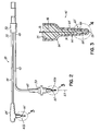
- Fig. 1 is a schematic illustration of an exemplary respiratory system including a patient temperature cable including temperature probes constructed in accordance with the principles of the present invention
- Fig. 2 is an enlarged side elevation view, not to scale, of the patient temperature cable of Fig. 1 ;
- Fig. 3 is an enlarged cross-sectional view, not to scale, of a thermistor-based temperature probe of Fig. 2 taken from encircled area 3 in Fig. 2 ;
- Figs. 4A and 4B are an enlarged cross-sectional views, not to scale, taken from encircled area 4 of Fig. 3 showing two exemplary embodiments of environmentally protected thermistor-based temperature probes constructed in accordance with the principles of the present invention.
- Fig. 1 is an exemplary respiratory system 10 for supplying breathable gases to a patient 12.
- the respiratory system 10 includes a ventilator 14, a humidification system 16 having a heater unit 18, a heatable container for water such as a disposable chamber 20, and a breathing circuit 21 having a first elongated hose or conduit 22 defining an inspiratory limb 22 and second elongated hose or conduit 24 defining an expiratory limb.
- Ventilator 14 drives breathable gas, such as oxygen, anesthetic gas and/or air, through gas conduit 25 and into an inlet of chamber 20.
- Water 26 is received in chamber 20, either by being poured in manually or automatically from a water supply 27 such as a bag or bottle, which may be vented.
- Chamber 20 is heated by a heater 28, such as hot plate and one or more heating elements, (not shown), of heater unit 18 to heat up the water 26 therein.
- Heated water vapor 29 may also be produced within chamber 20 above the level of water 26 therein.
- the gas from conduit 25 passes over or through the heated water 26 and/or through heated water vapor 29 to become heated and humidified before exiting the chamber 20 as heated and humidified gas. Examples of humidification systems are shown in aforementioned U.S. Patent Nos. 6,988,497 and 5,943,743 , and co-pending U.S. Patent Application Nos. 11/469,086 filed August 31, 2006 and 11/469,113 filed August 31, 2006 , the disclosures of all four of which are incorporated herein by reference in their entireties.
- the heated and humidified gas flows from chamber 20 to the patient 12 through inspiratory limb 22.
- a first end of inspiratory limb 22 is coupled to chamber 20 by a connecting member or joint 30, and a second end of inspiratory limb 22 is coupled to a breathing attachment 32 that facilitates delivery of the gas passed therethrough to patient 12.
- the breathing attachment 32 may couple to an invasive apparatus such as an endotrachael tube, or a non-invasive apparatus such as a mask that promotes gas delivery.
- the gas may be further heated while passing through inspiratory limb 22 to breathing attachment 32 by providing a heating circuit 34 associated with inspiratory limb 22.
- Another heating circuit 36 may be associated with expiratory limb 24, which allows exhaled air and other gas expelled from patient 12 to pass back to ventilator 14, the atmosphere or elsewhere.
- Respiratory system 10 also includes a patient temperature cable (PTC) 38 having one or more temperature probes 42 (referenced separately as 42a and 42b where two are used as in the exemplary embodiment shown herein) to provide thermal feedback to heater unit 18.
- PTC patient temperature cable
- the feedback received from the probes enable heater unit 18 to a vary the power levels to heater 28 and/or heater circuits 34, 36 in order to regulate the temperature of the gas supplied to the patient 12 at a pre-selected temperature set point conducive to proper respiration and lung viability.
- patient temperature cable 38 includes a first communication cable 43 having a first temperature probe 42a coupled thereto and a second communication cable 44 having a second temperature probe 42b coupled thereto.
- First temperature probe 42a may be partially inserted through an opening (not shown) in connecting member 30 and positioned so as to be in thermal communication with the inspiratory gas flowing through inspiratory limb 22, such as in the flow path thereof Alternatively, probe 42a may be positioned adjacent the flow path of inspiratory limb 22, but in thermal communication with the gas flowing therethrough.
- First temperature probe 42a is responsive to the temperature of the gas exiting chamber 20 and is electrically coupled to heater unit 18 by first communication cable 43, which has an end 48 electrically coupled to heater unit 18.
- second temperature probe 42b may be partially inserted through breathing attachment 32 and positioned so as to be in thermal communication with the inspiratory gas flowing through attachment 32 and into patient 12. Second temperature probe 42b may be located directly in the gas flow path of attachment 32 or adjacent the flow path, but in thermal communication with the gas flowing therethrough. Second temperature probe 42b is electrically coupled to heater unit 18 by second communication cable 44, which also has an end 50 electrically coupled to heater unit 18. Ends 48 and 50 may be advantageously secured together by a connector 52 to facilitate coupling the first and second cables 43, 44 to a mating socket (not shown) on heater unit 18.
- a controller 54 in heater unit 18 is operatively associated with heater 28 as at 56 (and with heater circuits 34, 36 as at 57) and adapted to control energization of heater 28 (and heater circuits 34, 36 in inspiratory and expiratory limbs 22, 24, respectively) in order to desirably heat water 26 so as to create water vapor 29 by which to heat and humidify the breathable gas passing through chamber 20.
- a microprocessor or logic circuit within controller 54 processes the information from temperature probe(s) 42 to determine whether any adjustments need to be made to the power supplied to heater 26 (or heater circuits 34 and 36).
- First temperature probe 42a may be coupled to first communication cable 43 by an overmold 58. More specifically, an end portion 60 of first communication cable 43 is typically inserted into the first temperature probe 42a and secured to an outer housing 62 ( Fig. 3 ) by a conventional fastener, such as a cable tie (not shown). To reinforce the connection, overmold 58 may be molded over end portion 60 and at least a proximal portion of outer housing 62. The end portion 60 and first temperature probe 42a may be coupled substantially along an axis 63 so that patient temperature cable 38 may be properly positioned in the respiratory system 10.
- second temperature probe 42b may be coupled to second communication cable 44 by an overmold 64.
- Second temperature probe 42b has the same general design as first temperature probe 42a, as will be described in greater detail below. Due to its particular location in the respiratory system 10, however, second temperature probe 42b may be arranged perpendicularly with respect to second communication cable 44. Thus, the portion of second communication cable 44 inserted into or immediately proximate housing 62, including a right-angle bend and overmold 64, may be configured to accommodate the particular orientation of second temperature probe 42b with respect to second communication cable 44.
- Overmolds 58 and 64 provide strain relief so that communication cables 43 and 44 do not separate from their respective temperature probes 42 when the cables are bent or placed in tension.
- overmolds 58 and 66 are formed from a thermoplastic resin, such as Santoprene TPV 8281-90MED, and have a durometer of approximately 90 Shore A.
- the shape and materials of the overmolds 58 and 64 may be selected to serve ergonomic functions as well, making the patient temperature cable 38 easier to grip and temperature probes 42 easier to handle.
- overmolds 58 and 64 may be designed to act as a moisture barrier to protect wires and other internal components of temperature probes 42 from damage.
- Temperature probe 42 includes a plastic probe housing 62 having a tip end 65 defining a cavity 66 therein. Situated within cavity 66 is a generally cylindrical container 68 in which a thermistor 70 is secured by epoxy 72 ( Figs. 4A and 4B ). Potting compound 74 may fill the interior 75 of probe housing 62 including any aspects of cavity 66 outside of container 68.
- Cavity 66 is sized to snugly receive container 68 therein so as to situate container 68 in close thermal relation to plastic housing 62 at tip end 64. To that end, the cross dimension of cavity 66 closely approximates the diameter of container 68. In one embodiment, the nominal diameter of cavity 66 is no more than about 0.020, and more advantageously no more than about 0.020 inches, larger than the diameter of container 68.
- the nominal radial distance between probe housing 62 and container 68 is advantageously no more than about 0.010 inches, and more advantageously no more than about 0.005 inches, such that heat transfer from probe housing 62 to container 68 is not adversely affected.
- Probe housing 62 in the area of tip end 64 is also sized to minimize the heat transmission path through probe housing 62 and into cavity 66.
- the wall thickness of probe housing 62, at least in the area of tip end 64 is no more than about 0.020 inches.
- thermistor 70 is environmentally protected by adapting container 68 to minimize moisture migration to thermistor 70 notwithstanding the high temperature and humidity levels encountered in normal operation of respiratory system 10.
- container 68 may be in the form of a tube 80 having a generally cylindrical sidewall 82 extending between open ends 84, 86 and defining axially elongated cylindrical space 88 therein.
- Thermistor 70 is situated in space 88, and held therein by epoxy 72, so as to be secured within container 68 with leads 76 extending out through end 86.
- thermistor 70 is generally axially centered between ends 84 and 86, such that thermistor 70 is generally equidistant from ends 84 and 86 to thereby balance any generally axial moisture migration paths such as from ends 84, 86.
- Tube 80 may be metal such that epoxy 72 alone is sufficient to secure thermistor 70 therein and to help seal off ends 84 and 86.
- thermistor 70 may advantageously touch sidewall 82.
- tube 80 is of plastic, such as polyimide
- thermistor 70 is to be encapsulated and also generally radially centered in tube 80 so as to be generally equidistant from sidewall 82 rather than touching same. If desired, and as shown in Fig.
- thermistor 70 before thermistor 70 is placed within space 88, it is coated with a thin encapsulating layer 90 of epoxy, which may be of the same material as epoxy 72. Thin layer 90 helps prevent thermistor 70 from touching sidewall 82 and aids in radially centering thermistor 70 in space 88. To that end, layer 90 may advantageously have a generally uniform maximum thickness (radially) which provides a layer that fits snugly within space 88 in the radial direction. Once thermistor with layer 90 thereon is inserted into space 88 and properly centered (particularly axially), epoxy 72 is applied to secure thermistor 70 in space 88.
- container 68 may take the form of a can 92 having a generally cylindrical sidewall 94 defining axially elongated space 95 closed at one end 96, such as a bottom end, and open at the other end 98, such as a top end.
- Can 92 could be made by utilizing tube 80 and welding a lid to, or otherwise closing, end 84 thereof to define closed end 96.
- can 92 can be formed, such as by drawing, so as to have sidewall 94 and closed end 96.
- thermistor 70 may be placed directly into can 92 in contact with closed end 96 and/or sidewall 92, and then secured therein with epoxy 72 to close off end 98.
- thermistor 70 is situated close to or at end 96, so as to be as far from otherwise (but for epoxy 72) open end 98 as possible to thereby provide a long moisture migration path from the most likely source of moisture migration, which is considered to be at open end 98.
- can 92 of plastic such as polyimide
- thermistor 70 may be pre-coated with layer 90 as above-described before being inserted into can 92 and secured by epoxy 72. Further, thermistor 70 may advantageously be axially and/or radially centered within can 92.
- Epoxy 72 may be selected to have relatively high thermal conductivity and /or low durometer so as to provide good heat transfer to thermistor 70 while also avoiding rigid stress forces thereon.
- An epoxy having those characteristics is Stycast 1090 low density, syntactic foam, epoxy encapsulant available from Emerson & Cuming, a National Starch & Chemical Company.
- potting compound 74 is selected from a material with a relatively low thermal conductivity so as to reduce or minimize heat transfer therethrough thus focusing the heat transfer toward thermistor 70. Potting compound 74 may be a two-part room curable silicone an example of which is Dow MDX4-4210, although other potting compounds may be used depending upon the desired performance characteristics of the probe 42.
- a low thermal conductivity potting compound (not shown) could first be applied in the area of tip end 64 to thus provide a dual potting temperature probe as described in concurrently-filed U.S. Patent Application Serial No. 11/927,020 , entitled “Dual Potting Temperature Probe", Attorney Docket NO. MDXCP-24US, the disclosure of which is incorporated herein by reference in its entirety.
- Probe housing 62 may be molded from a plastic material that has a relatively high thermal conductivity, such as greater than the thermal conductivity of potting compound 74, but also a relatively low electrical conductivity, excellent chemical resistance and high dimensional accuracy for manufacturing purposes.
- outer housing 62 may be molded from a thermoplastic resin reinforced with glass fibers, such as Udel ® GF-120 or a similar polysulfone resin available from Solvay Corporation.
- temperature probes 42 ofpatient temperature cable 38 are located in respiratory system 10 as described above and cable 38 is coupled to heater unit 18. Temperature probes 42 are in thermal communication with the heated and humidified gas flowing through inspiratory limb 22 and communicate temperature information of the gas to heater unit 18. Due to the particular construction of temperature probes 42, the probes are capable of quickly responding to thermal changes in the gas, while providing an adequate barrier to moisture transmission to thermistor(s) 70 to at least gain a meaningful useful life ofthermistor(s) 70 before it drifts out of useful range. Heater unit 18 may quickly adjust the temperature of heater 26 and/or heater circuits 34, 36 so as to maintain a temperature set point.
- heater 26 may be constructed so as to have a similar response time, i.e., heater 26 is capable of quickly heating up or cooling down.
- heater 26 capable of utilizing the improved response time of the temperature probes 42 is disclosed in concurrently filed U.S. Patent Application Serial No. 11/926,982 , entitled “Hot Plate Heater for a Respiratory System", Attorney Docket No. MDXCP-27US, which is incorporated by reference herein in its entirety.
- the quick response time of both the temperature probes and heater provide enhanced control over the heating and humidification of the breathable gas(es) to maintain a close tolerance to the pre-selected set point conditions that constitutes a considerable improvement over the set point tolerances achieved in prior respiratory systems.
- thermistor-based temperature probe for use in a respiratory system in which the thermistor is environmentally protected to reduce moisture migration thereagainst but without adversely impacting the temperature response thereof
Landscapes
- Health & Medical Sciences (AREA)
- Emergency Medicine (AREA)
- Pulmonology (AREA)
- Engineering & Computer Science (AREA)
- Anesthesiology (AREA)
- Biomedical Technology (AREA)
- Heart & Thoracic Surgery (AREA)
- Hematology (AREA)
- Life Sciences & Earth Sciences (AREA)
- Animal Behavior & Ethology (AREA)
- General Health & Medical Sciences (AREA)
- Public Health (AREA)
- Veterinary Medicine (AREA)
- Physics & Mathematics (AREA)
- General Physics & Mathematics (AREA)
- Measurement Of The Respiration, Hearing Ability, Form, And Blood Characteristics Of Living Organisms (AREA)
- Measuring Temperature Or Quantity Of Heat (AREA)
- Thermistors And Varistors (AREA)
Applications Claiming Priority (1)
| Application Number | Priority Date | Filing Date | Title |
|---|---|---|---|
| US11/927,077 US8059947B2 (en) | 2007-10-29 | 2007-10-29 | Environmentally protected thermistor for respiratory system |
Publications (2)
| Publication Number | Publication Date |
|---|---|
| EP2056082A2 true EP2056082A2 (de) | 2009-05-06 |
| EP2056082A3 EP2056082A3 (de) | 2014-03-05 |
Family
ID=40307399
Family Applications (1)
| Application Number | Title | Priority Date | Filing Date |
|---|---|---|---|
| EP08167316.2A Withdrawn EP2056082A3 (de) | 2007-10-29 | 2008-10-22 | Vor Umwelteinflüssen geschützter Thermistor für ein Beatmungssystem |
Country Status (4)
| Country | Link |
|---|---|
| US (1) | US8059947B2 (de) |
| EP (1) | EP2056082A3 (de) |
| JP (1) | JP5328293B2 (de) |
| AU (1) | AU2008237551B2 (de) |
Cited By (1)
| Publication number | Priority date | Publication date | Assignee | Title |
|---|---|---|---|---|
| EP4070058B1 (de) * | 2019-12-03 | 2024-05-01 | Nihon Kohden Corporation | Wärmeempfindliche sonde |
Families Citing this family (26)
| Publication number | Priority date | Publication date | Assignee | Title |
|---|---|---|---|---|
| US8511305B2 (en) * | 2007-10-29 | 2013-08-20 | Smiths Medical Asd, Inc. | Redundant power control for respiratory system heaters |
| US8122882B2 (en) * | 2007-10-29 | 2012-02-28 | Smiths Medical Asd, Inc. | Rainout reduction in a breathing circuit |
| DE102008029192A1 (de) * | 2008-03-13 | 2009-09-24 | Epcos Ag | Fühler zum Erfassen einer physikalischen Größe und Verfahren zur Herstellung des Fühlers |
| WO2013092103A1 (de) * | 2011-12-22 | 2013-06-27 | Endress+Hauser Flowtec Ag | Verfahren zur erkennung eines tröpfchenniederschlags an einem beheizten temperaturfühler |
| JP6258873B2 (ja) * | 2012-02-24 | 2018-01-10 | コーニンクレッカ フィリップス エヌ ヴェKoninklijke Philips N.V. | 加湿を含む呼吸療法のためのレインアウト保護 |
| GB2541301B (en) * | 2012-03-15 | 2017-07-12 | Fisher & Paykel Healthcare Ltd | Respiratory gas humidification system |
| GB2577634B (en) | 2012-04-27 | 2020-09-30 | Fisher & Paykel Healthcare Ltd | Respiratory humidification apparatus |
| KR101546836B1 (ko) | 2013-05-14 | 2015-11-20 | 주식회사 멕 아이씨에스 | 가습 겸용 제습 시스템 |
| EP3862041B1 (de) | 2013-06-25 | 2023-10-25 | ResMed Pty Ltd | Auslassanschlussanordnung |
| US10549060B2 (en) | 2013-06-25 | 2020-02-04 | ResMed Pty Ltd | Outlet connection assembly and method of making the same |
| EP3622993B8 (de) | 2013-09-13 | 2021-08-25 | Fisher & Paykel Healthcare Limited | Heizsockel mit einem schutz zur steuerung der bewegung einer befeuchterkammer |
| GB2583046B8 (en) | 2013-09-13 | 2021-04-28 | Fisher & Paykel Healthcare Ltd | Resilient probe mount for a humidification system |
| EP4173663B1 (de) | 2013-12-17 | 2025-09-03 | ResMed Pty Ltd | Gerät zur anwendung in der behandlung respiratorischer störungen |
| GB2558102B (en) | 2013-12-20 | 2018-11-28 | Fisher & Paykel Healthcare Ltd | Humidification system connections |
| US10449319B2 (en) | 2014-02-07 | 2019-10-22 | Fisher & Paykel Healthcare Limited | Respiratory humidification system |
| USD762843S1 (en) | 2014-03-18 | 2016-08-02 | Resmed Limited | Air delivery tube |
| WO2015167347A1 (en) | 2014-05-02 | 2015-11-05 | Fisher & Paykel Healthcare Limited | Gas humidification arrangement |
| EP3142737B1 (de) | 2014-05-13 | 2020-07-08 | Fisher & Paykel Healthcare Limited | Eine anschlusskappe für eine vorrichtung zum anfeuchten von gasen und eine vorrichtung zum anfeuchten von gasen |
| EP3607988B1 (de) | 2014-06-03 | 2025-09-10 | Fisher & Paykel Healthcare Limited | Befeuchtungskammer für eine atemtherapievorrichtung |
| EP3220992B1 (de) | 2014-11-17 | 2021-06-23 | Fisher & Paykel Healthcare Limited | Befeuchtung von atemgasen |
| USD805630S1 (en) | 2016-02-02 | 2017-12-19 | Resmed Limited | Air delivery tube |
| SG10202106016TA (en) | 2016-12-07 | 2021-07-29 | Fisher and paykel healthcare ltd | Sensing arrangements for medical devices |
| DE102018102600A1 (de) * | 2018-02-06 | 2019-08-08 | Tdk Electronics Ag | Temperatursensor |
| DE102018102709A1 (de) * | 2018-02-07 | 2019-08-08 | Tdk Electronics Ag | Temperatursensor und ein Verfahren zur Herstellung des Temperatursensors |
| EP3897798B1 (de) | 2018-12-18 | 2024-06-19 | ResMed Pty Ltd | Befeuchterbehälter |
| US11682505B2 (en) | 2020-03-03 | 2023-06-20 | Deroyal Industries, Inc. | Radiation curable thermistor encapsulation |
Citations (3)
| Publication number | Priority date | Publication date | Assignee | Title |
|---|---|---|---|---|
| US5943743A (en) | 1998-08-11 | 1999-08-31 | Builder's Best, Inc. | Hose clamp |
| US6078730A (en) | 1995-11-13 | 2000-06-20 | Fisher & Paykel Limited | Heat respiratory conduit |
| US6988497B2 (en) | 2002-09-18 | 2006-01-24 | Medex Cardio-Pulmonary, Inc. | Apparatus for equalizing air pressure in air respiratory system |
Family Cites Families (44)
| Publication number | Priority date | Publication date | Assignee | Title |
|---|---|---|---|---|
| US2000400A (en) * | 1931-11-11 | 1935-05-07 | James G Maclaren | Pneumatic dispatch carrier |
| US3402378A (en) * | 1965-09-10 | 1968-09-17 | Aero Med Thermal Instr Company | Electronic clinical thermometer and probe therefor |
| US3593704A (en) * | 1967-12-11 | 1971-07-20 | Ardath M Schwab | Pulse sensor for body pulse rate measuring means |
| US3678751A (en) * | 1970-07-01 | 1972-07-25 | Carver A Mead | Thermometer probe |
| US3713899A (en) * | 1970-11-12 | 1973-01-30 | Ford Motor Co | Thermocouple probe |
| US3738173A (en) * | 1971-11-22 | 1973-06-12 | Ivac Corp | Temperature sensing probe and disposable probe cover |
| GB1545543A (en) * | 1975-07-23 | 1979-05-10 | Fisher & Paykel | Temperature sensors |
| US4098662A (en) * | 1975-12-24 | 1978-07-04 | Betz Laboratories, Inc. | Corrosion probe for use in measuring corrosion rate under specified heat transfer conditions |
| US4138878A (en) * | 1976-12-03 | 1979-02-13 | Rohrback Corporation | Method and apparatus for detecting and measuring scale |
| US4183248A (en) * | 1978-08-08 | 1980-01-15 | Rwb Labs | Fast response electronic thermometer probe |
| JPS5539006A (en) | 1978-09-13 | 1980-03-18 | Hitachi Ltd | Water-proof thermister |
| US4464981A (en) * | 1983-04-01 | 1984-08-14 | Bunn-O-Matic Corporation | Beverage making machine with hot water faucet |
| NZ206715A (en) * | 1983-12-22 | 1988-10-28 | Fisher & Paykel | Forming a thermistor temperature probe |
| JPS60219526A (ja) | 1984-04-16 | 1985-11-02 | Terumo Corp | 電子体温計およびその製造方法 |
| JPS61111428A (ja) * | 1984-11-06 | 1986-05-29 | Terumo Corp | 電子体温計 |
| JPS633101U (de) * | 1986-06-24 | 1988-01-11 | ||
| US5178468A (en) * | 1988-08-25 | 1993-01-12 | Terumo Kabushiki Kaisha | Temperature measuring probe and electronic clinical thermometer equipped with same |
| US4934831A (en) * | 1989-03-20 | 1990-06-19 | Claud S. Gordon Company | Temperature sensing device |
| JPH03118432A (ja) | 1989-09-29 | 1991-05-21 | Terumo Corp | 電子体温計及びその製法 |
| JP2527557Y2 (ja) * | 1990-05-25 | 1997-03-05 | シチズン時計株式会社 | 電子体温計の構造 |
| JP2566613Y2 (ja) * | 1992-03-17 | 1998-03-30 | ティーディーケイ株式会社 | 温度センサ |
| US5349946A (en) * | 1992-10-07 | 1994-09-27 | Mccomb R Carter | Microprocessor controlled flow regulated molecular humidifier |
| US5348397A (en) * | 1993-03-29 | 1994-09-20 | Ferrari R Keith | Medical temperature sensing probe |
| US5392770A (en) * | 1993-06-29 | 1995-02-28 | Clawson; Burrell E. | Tubing circuit systems for humidified respiratory gas |
| US5667306A (en) * | 1995-04-27 | 1997-09-16 | Montreuil; Richard | Numerical temperature reading apparatus for spa, swimming pool and whirlpool |
| US5743646A (en) * | 1996-07-01 | 1998-04-28 | General Motors Corporation | Temperature sensor with improved thermal barrier and gas seal between the probe and housing |
| EP0818671A3 (de) * | 1996-07-12 | 1998-07-08 | Isuzu Ceramics Research Institute Co., Ltd. | Thermo-element mit keramischer Hülle |
| JPH10221176A (ja) | 1997-02-04 | 1998-08-21 | Toshiba Glass Co Ltd | 電子体温計 |
| US5943473A (en) * | 1997-05-29 | 1999-08-24 | Levine; Walter | Heated cartridge humidifier |
| CA2617287C (en) * | 1997-06-17 | 2011-11-15 | Fisher & Paykel Healthcare Limited | Respiratory humidification system |
| JPH11132866A (ja) * | 1997-10-24 | 1999-05-21 | Matsushita Electric Ind Co Ltd | サーミスタ温度センサ |
| JP2001242016A (ja) | 2000-02-29 | 2001-09-07 | Citizen Electronics Co Ltd | 電子体温計 |
| US6918389B2 (en) * | 2000-03-21 | 2005-07-19 | Fisher & Paykel Healthcare Limited | Breathing assistance apparatus |
| JP2002022555A (ja) * | 2000-07-05 | 2002-01-23 | Matsushita Electric Ind Co Ltd | 温度センサ |
| US7043979B2 (en) * | 2001-01-31 | 2006-05-16 | Fisher & Paykel Healthcare Limited | Respiratory humidification system |
| JP2006501881A (ja) * | 2002-07-31 | 2006-01-19 | フィッシャー アンド ペイケル ヘルスケア リミテッド | 加湿システムのための隔離された温度センサ |
| US6676290B1 (en) * | 2002-11-15 | 2004-01-13 | Hsueh-Yu Lu | Electronic clinical thermometer |
| US6918696B2 (en) * | 2003-01-15 | 2005-07-19 | Denso Corporation | Temperature sensor and method for manufacturing the same |
| JP4620400B2 (ja) * | 2004-07-16 | 2011-01-26 | 日本特殊陶業株式会社 | 温度センサ、温度センサの製造方法 |
| US7316507B2 (en) * | 2005-11-03 | 2008-01-08 | Covidien Ag | Electronic thermometer with flex circuit location |
| US7458718B2 (en) * | 2006-02-22 | 2008-12-02 | Honeywell International Inc. | Temperature sensor that achieves a fast response in an exhaust gas environment |
| US7665890B2 (en) * | 2006-06-22 | 2010-02-23 | Watlow Electric Manufacturing Company | Temperature sensor assembly and method of manufacturing thereof |
| US7722016B2 (en) * | 2006-08-31 | 2010-05-25 | Medex Cardio-Pulmonary, Inc. | Float for humidification chamber |
| US20080054497A1 (en) * | 2006-08-31 | 2008-03-06 | Medex Cardio-Pulmonary, Inc.. | Vented cap humidification system |
-
2007
- 2007-10-29 US US11/927,077 patent/US8059947B2/en not_active Expired - Fee Related
-
2008
- 2008-10-22 EP EP08167316.2A patent/EP2056082A3/de not_active Withdrawn
- 2008-10-28 JP JP2008277054A patent/JP5328293B2/ja not_active Expired - Fee Related
- 2008-10-28 AU AU2008237551A patent/AU2008237551B2/en not_active Ceased
Patent Citations (3)
| Publication number | Priority date | Publication date | Assignee | Title |
|---|---|---|---|---|
| US6078730A (en) | 1995-11-13 | 2000-06-20 | Fisher & Paykel Limited | Heat respiratory conduit |
| US5943743A (en) | 1998-08-11 | 1999-08-31 | Builder's Best, Inc. | Hose clamp |
| US6988497B2 (en) | 2002-09-18 | 2006-01-24 | Medex Cardio-Pulmonary, Inc. | Apparatus for equalizing air pressure in air respiratory system |
Cited By (2)
| Publication number | Priority date | Publication date | Assignee | Title |
|---|---|---|---|---|
| EP4070058B1 (de) * | 2019-12-03 | 2024-05-01 | Nihon Kohden Corporation | Wärmeempfindliche sonde |
| US12510417B2 (en) | 2019-12-03 | 2025-12-30 | Nihon Kohden Corporation | Thermosensitive probe |
Also Published As
| Publication number | Publication date |
|---|---|
| AU2008237551A1 (en) | 2009-05-14 |
| US8059947B2 (en) | 2011-11-15 |
| JP2009109496A (ja) | 2009-05-21 |
| EP2056082A3 (de) | 2014-03-05 |
| AU2008237551B2 (en) | 2014-05-29 |
| US20090110378A1 (en) | 2009-04-30 |
| JP5328293B2 (ja) | 2013-10-30 |
Similar Documents
| Publication | Publication Date | Title |
|---|---|---|
| US8059947B2 (en) | Environmentally protected thermistor for respiratory system | |
| US8303173B2 (en) | Dual potting temperature probe | |
| US20250312551A1 (en) | Medical tubes for respiratory systems | |
| JP7384850B2 (ja) | 患者にガスを供給する装置 | |
| EP2195061B1 (de) | Beatmungssystem | |
| CN109550129B (zh) | 医用管以及其制造方法 | |
| JP5443991B2 (ja) | 呼吸装置に用いるための導管 | |
| CA2780516C (en) | Heated conduit for respiratory humidification | |
| CN101641130B (zh) | 在气体通路的患者端设有rfid标签传感器的加湿设备 | |
| JP7464659B2 (ja) | フィルターアセンブリ | |
| CN1671437A (zh) | 增湿系统的隔离式温度传感器 | |
| WO2005028012A1 (en) | A connector | |
| WO2004108218A1 (en) | A probe and breathing circuit | |
| CN113117197A (zh) | 通气接头和通气治疗设备 | |
| HK1127805A (en) | Environmentally protected thermistor for respiratory system | |
| CN214762714U (zh) | 通气接头和通气治疗设备 | |
| US20240024609A1 (en) | Concentric breathing circuit with boost zone |
Legal Events
| Date | Code | Title | Description |
|---|---|---|---|
| PUAI | Public reference made under article 153(3) epc to a published international application that has entered the european phase |
Free format text: ORIGINAL CODE: 0009012 |
|
| AK | Designated contracting states |
Kind code of ref document: A2 Designated state(s): AT BE BG CH CY CZ DE DK EE ES FI FR GB GR HR HU IE IS IT LI LT LU LV MC MT NL NO PL PT RO SE SI SK TR |
|
| AX | Request for extension of the european patent |
Extension state: AL BA MK RS |
|
| REG | Reference to a national code |
Ref country code: HK Ref legal event code: DE Ref document number: 1127805 Country of ref document: HK |
|
| PUAL | Search report despatched |
Free format text: ORIGINAL CODE: 0009013 |
|
| AK | Designated contracting states |
Kind code of ref document: A3 Designated state(s): AT BE BG CH CY CZ DE DK EE ES FI FR GB GR HR HU IE IS IT LI LT LU LV MC MT NL NO PL PT RO SE SI SK TR |
|
| AX | Request for extension of the european patent |
Extension state: AL BA MK RS |
|
| RIC1 | Information provided on ipc code assigned before grant |
Ipc: G01K 1/08 20060101AFI20140128BHEP Ipc: A61M 16/10 20060101ALN20140128BHEP Ipc: A61M 16/16 20060101ALN20140128BHEP |
|
| 17P | Request for examination filed |
Effective date: 20140513 |
|
| RBV | Designated contracting states (corrected) |
Designated state(s): AT BE BG CH CY CZ DE DK EE ES FI FR GB GR HR HU IE IS IT LI LT LU LV MC MT NL NO PL PT RO SE SI SK TR |
|
| AKX | Designation fees paid |
Designated state(s): AT BE BG CH CY CZ DE DK EE ES FI FR GB GR HR HU IE IS IT LI LT LU LV MC MT NL NO PL PT RO SE SI SK TR |
|
| REG | Reference to a national code |
Ref country code: HK Ref legal event code: WD Ref document number: 1127805 Country of ref document: HK |
|
| STAA | Information on the status of an ep patent application or granted ep patent |
Free format text: STATUS: THE APPLICATION IS DEEMED TO BE WITHDRAWN |
|
| 18D | Application deemed to be withdrawn |
Effective date: 20160503 |