EP2056366A1 - Dispositif électroluminescent et dispositif d'éclairage - Google Patents
Dispositif électroluminescent et dispositif d'éclairage Download PDFInfo
- Publication number
- EP2056366A1 EP2056366A1 EP07805885A EP07805885A EP2056366A1 EP 2056366 A1 EP2056366 A1 EP 2056366A1 EP 07805885 A EP07805885 A EP 07805885A EP 07805885 A EP07805885 A EP 07805885A EP 2056366 A1 EP2056366 A1 EP 2056366A1
- Authority
- EP
- European Patent Office
- Prior art keywords
- fluorescent material
- light emitting
- emission intensity
- light
- wavelength
- Prior art date
- Legal status (The legal status is an assumption and is not a legal conclusion. Google has not performed a legal analysis and makes no representation as to the accuracy of the status listed.)
- Granted
Links
Images



Classifications
-
- C—CHEMISTRY; METALLURGY
- C09—DYES; PAINTS; POLISHES; NATURAL RESINS; ADHESIVES; COMPOSITIONS NOT OTHERWISE PROVIDED FOR; APPLICATIONS OF MATERIALS NOT OTHERWISE PROVIDED FOR
- C09K—MATERIALS FOR MISCELLANEOUS APPLICATIONS, NOT PROVIDED FOR ELSEWHERE
- C09K11/00—Luminescent materials, e.g. electroluminescent or chemiluminescent
- C09K11/08—Luminescent materials, e.g. electroluminescent or chemiluminescent containing inorganic luminescent materials
- C09K11/77—Luminescent materials, e.g. electroluminescent or chemiluminescent containing inorganic luminescent materials containing rare earth metals
- C09K11/7728—Luminescent materials, e.g. electroluminescent or chemiluminescent containing inorganic luminescent materials containing rare earth metals containing europium
- C09K11/77347—Silicon Nitrides or Silicon Oxynitrides
-
- C—CHEMISTRY; METALLURGY
- C09—DYES; PAINTS; POLISHES; NATURAL RESINS; ADHESIVES; COMPOSITIONS NOT OTHERWISE PROVIDED FOR; APPLICATIONS OF MATERIALS NOT OTHERWISE PROVIDED FOR
- C09K—MATERIALS FOR MISCELLANEOUS APPLICATIONS, NOT PROVIDED FOR ELSEWHERE
- C09K11/00—Luminescent materials, e.g. electroluminescent or chemiluminescent
- C09K11/08—Luminescent materials, e.g. electroluminescent or chemiluminescent containing inorganic luminescent materials
- C09K11/77—Luminescent materials, e.g. electroluminescent or chemiluminescent containing inorganic luminescent materials containing rare earth metals
- C09K11/7728—Luminescent materials, e.g. electroluminescent or chemiluminescent containing inorganic luminescent materials containing rare earth metals containing europium
- C09K11/77348—Silicon Aluminium Nitrides or Silicon Aluminium Oxynitrides
-
- H—ELECTRICITY
- H10—SEMICONDUCTOR DEVICES; ELECTRIC SOLID-STATE DEVICES NOT OTHERWISE PROVIDED FOR
- H10H—INORGANIC LIGHT-EMITTING SEMICONDUCTOR DEVICES HAVING POTENTIAL BARRIERS
- H10H20/00—Individual inorganic light-emitting semiconductor devices having potential barriers, e.g. light-emitting diodes [LED]
- H10H20/80—Constructional details
- H10H20/85—Packages
-
- H—ELECTRICITY
- H10—SEMICONDUCTOR DEVICES; ELECTRIC SOLID-STATE DEVICES NOT OTHERWISE PROVIDED FOR
- H10H—INORGANIC LIGHT-EMITTING SEMICONDUCTOR DEVICES HAVING POTENTIAL BARRIERS
- H10H20/00—Individual inorganic light-emitting semiconductor devices having potential barriers, e.g. light-emitting diodes [LED]
- H10H20/80—Constructional details
- H10H20/85—Packages
- H10H20/851—Wavelength conversion means
-
- H—ELECTRICITY
- H10—SEMICONDUCTOR DEVICES; ELECTRIC SOLID-STATE DEVICES NOT OTHERWISE PROVIDED FOR
- H10H—INORGANIC LIGHT-EMITTING SEMICONDUCTOR DEVICES HAVING POTENTIAL BARRIERS
- H10H20/00—Individual inorganic light-emitting semiconductor devices having potential barriers, e.g. light-emitting diodes [LED]
- H10H20/80—Constructional details
- H10H20/85—Packages
- H10H20/851—Wavelength conversion means
- H10H20/8511—Wavelength conversion means characterised by their material, e.g. binder
- H10H20/8512—Wavelength conversion materials
-
- H—ELECTRICITY
- H10—SEMICONDUCTOR DEVICES; ELECTRIC SOLID-STATE DEVICES NOT OTHERWISE PROVIDED FOR
- H10W—GENERIC PACKAGES, INTERCONNECTIONS, CONNECTORS OR OTHER CONSTRUCTIONAL DETAILS OF DEVICES COVERED BY CLASS H10
- H10W72/00—Interconnections or connectors in packages
- H10W72/50—Bond wires
- H10W72/551—Materials of bond wires
- H10W72/552—Materials of bond wires comprising metals or metalloids, e.g. silver
- H10W72/5522—Materials of bond wires comprising metals or metalloids, e.g. silver comprising gold [Au]
-
- Y—GENERAL TAGGING OF NEW TECHNOLOGICAL DEVELOPMENTS; GENERAL TAGGING OF CROSS-SECTIONAL TECHNOLOGIES SPANNING OVER SEVERAL SECTIONS OF THE IPC; TECHNICAL SUBJECTS COVERED BY FORMER USPC CROSS-REFERENCE ART COLLECTIONS [XRACs] AND DIGESTS
- Y02—TECHNOLOGIES OR APPLICATIONS FOR MITIGATION OR ADAPTATION AGAINST CLIMATE CHANGE
- Y02B—CLIMATE CHANGE MITIGATION TECHNOLOGIES RELATED TO BUILDINGS, e.g. HOUSING, HOUSE APPLIANCES OR RELATED END-USER APPLICATIONS
- Y02B20/00—Energy efficient lighting technologies, e.g. halogen lamps or gas discharge lamps
Definitions
- the present invention relates to a light emitting device such as a white light emitting diode lamp and a light emitting apparatus that uses the device, and relates particularly to a light emitting device designed for use within the field of illumination and an illumination device that uses the light emitting device.
- a light emitting device such as a white light emitting diode lamp and a light emitting apparatus that uses the device
- these white light emitting diode lamps will become widespread as energy efficient illumination devices. Furthermore, the fact that they contain no materials such as mercury that have an adverse environmental impact is also a significant advantage. Moreover, because the dimensions of these elements are small, they can be used in many applications, such as the backlights for liquid crystal display devices or within mobile telephones.
- the term "light emitting diode” is abbreviated as LED.
- White LEDs that combine a LED element that emits light having a short wavelength such as a blue light or an ultraviolet light and a fluorescent material that is excited by absorbing some or all of the light emitted from the LED element and then emits a fluorescent light of a longer wavelength such as a yellow fluorescent light are already known.
- white LEDs composed of a compound semiconductor blue LED element and a cerium-activated yttrium-aluminum-garnet fluorescent material that absorbs blue light and then emits a yellow fluorescent light that is a complementary color to blue are disclosed in Patent Document 1, Patent Document 2, and Non-Patent Document 1.
- Patent Document 3 discloses a technique in which a red fluorescent material such as (Sr 1-x-y-z Ba x Ca y ) 2 Si 5 N 8 :Eu z 2+ , SrS:Eu, CaS:Eu or (Ca x Sr 1 . x )S:Eu 2+ is added to a white LED composed of a blue LED element and a cerium-activated yttrium-aluminum-garnet fluorescent material. Similar techniques are also disclosed in Patent Document 4 and Non-Patent Document 2.
- Patent Document 5 discloses a technique for realizing a white LED using a blue LED element, a fluorescent material that is excited by blue light and emits a green light, and a fluorescent material that is excited by blue light and emits a red light. Furthermore, a white LED that uses SrGa 2 S 4 :Eu 2+ , which is a fluorescent material that is excited by blue light and emits a green light, and SrS:Eu 2+ , which is a fluorescent material that is excited by blue light and emits a red light, is disclosed in Non-Patent Document 3.
- Patent Document 6 discloses a technique for realizing a white light having a high color rendering characteristic by using a combination of an ultraviolet LED element, a fluorescent material that is excited by ultraviolet light and emits a blue light, a fluorescent material that is excited by ultraviolet light and emits a green light, and a fluorescent material that is excited by ultraviolet light and emits a red light.
- Patent Document 7 discloses a europium (Eu)-activated calcium (Ca) solid solution ⁇ -SiAlON fluorescent material. This fluorescent material is excited by blue light and emits a yellow light, and can therefore be used favorably as a wavelength conversion material for a white LED. This fluorescent material is described in detail in Non-Patent Document 4. A low color temperature white LED lamp that uses this fluorescent material and exhibits excellent chromaticity stability upon temperature variation is disclosed in Non-Patent Document 5.
- fluorescent materials have been predominantly oxides or sulfides, and have required further improvement in terms of their durability and their properties under high-temperature environments.
- development efforts have been focused on developing oxynitride fluorescent materials and nitride fluorescent materials that exhibit superior long-term reliability and high-temperature properties.
- oxynitride fluorescent materials or sulfide fluorescent materials are the primary materials being researched.
- a white LED is then fabricated using a combination of these fluorescent materials and a blue LED element, achieving a white LED having a high color rendering characteristic has proven difficult.
- the present invention takes the above circumstances into consideration, with an object of providing a white LED with a high color rendering characteristic, that uses a blue LED element and has an average color rendering index exceeding 90.
- the present invention provides a light emitting device that includes a semiconductor light emitting element that emits a blue light or a blue-violet light, and a fluorescent material that absorbs some or all of the light emitted from the semiconductor light emitting element and emits a fluorescent light of a wavelength different from the absorbed light, wherein the fluorescent material is a mixed fluorescent material obtained by mixing a first fluorescent material that emits a blue-green light or a green light, a second fluorescent material that has a peak emission wavelength longer than that of the first fluorescent material and emits a green light or a yellow-green light, a third fluorescent material that has a 1 peak emission wavelength longer than that of the second fluorescent material and emits a yellow-green light, a yellow light or a yellow-red light, and a fourth fluorescent material that has a peak emission wavelength longer than that of the third fluorescent material and emits a yellow-red light or a red light.
- the fluorescent material is a mixed fluorescent material obtained by mixing a first fluorescent material that emits a blue-green light
- the first fluorescent material is preferably an oxynitride crystal fluorescent material represented by a general formula Ba x(1-r) Si y O z N (2x+4y-2z)/3 :Eu xr
- the second fluorescent material is preferably a europium-activated ⁇ -SiAlON fluorescent material
- the third fluorescent material is preferably a europium-activated ⁇ -SiAlON fluorescent material
- the fourth fluorescent material is preferably a nitride crystal red fluorescent material represented by a general formula (Ca,Eu)AlSiN 3 .
- the above ⁇ -SiAlON fluorescent material is preferably represented by a general formula Ca q Eu r (Si,Al) 12 (O,N) 16 , wherein the main phase has an ⁇ -SiAlON crystal structure, q is not less than 0.75 and not more than 1.0, and r is not less than 0.03 and not more than 0.10.
- the above ⁇ -SiAlON fluorescent material is preferably represented by a general formula Eu s (Si,Al) 6-s (O,N) 8 , wherein the main phase has a ⁇ -SiAlON crystal structure, and s is not less than 0.011 and not more than 0.019.
- x is preferably not less than 0.8 and not more than 1.2
- y is preferably not less than 1.6 and not more than 2.4
- z is preferably not less than 1.6 and not more than 2.4
- r is preferably not less than 0.015 and not more than 0.10.
- the ratio between the emission intensity at a wavelength of 380 to 475 nm, the emission intensity at a wavelength of 475 to 520 nm, the emission intensity at a wavelength of 520 to 560 nm, the emission intensity at a wavelength of 560 to 615 nm and the emission intensity at a wavelength of 615 to 780 nm is preferably 1 : 1.6 : 2.4 : 4.2 : 9.5.
- the mixed fluorescent material is preferably a material obtained by mixing the first fluorescent material, the second fluorescent material, the third fluorescent material and the fourth fluorescent material in a mass ratio of(2.5 ⁇ D/A):(1.9 ⁇ D/B):(1.5 ⁇ D/C):1, wherein A is the peak emission intensity of the first fluorescent material, B is the peak emission intensity of the second fluorescent material, C is the peak emission intensity of the third fluorescent material, and D is the peak emission intensity of the fourth fluorescent material, which are measured using a spectrally corrected fluorescence spectrophotometer.
- the mixed fluorescent material is preferably a material obtained by mixing the first fluorescent material, the second fluorescent material, the third fluorescent material and the fourth fluorescent material in a mass ratio of 6:8:7:3.
- the ratio between the emission intensity at a wavelength of 380 to 475 nm, the emission intensity at a wavelength of 475 to 520 nm, the emission intensity at a wavelength of 520 to 560 nm, the emission intensity at a wavelength of 560 to 615 nm and the emission intensity at a wavelength of 615 to 780 nm is preferably 1 : 1.0 : 1.5 : 2.3 : 4.6.
- the mixed fluorescent material is preferably a material obtained by mixing the first fluorescent material, the second fluorescent material, the third fluorescent material and the fourth fluorescent material in a mass ratio of (3.7 ⁇ D/A):(12.8 ⁇ D/B):(1.8 ⁇ D/C): wherein A is the peak emission intensity of the first fluorescent material, B is the peak emission intensity of the second fluorescent material, C is the peak emission intensity of the third fluorescent material, and D is the peak emission intensity of the fourth fluorescent material, which are measured using a spectrally corrected fluorescence spectrophotometer.
- the mixed fluorescent material is preferably a material obtained by mixing the first fluorescent material, the second fluorescent material, the third fluorescent material and the fourth fluorescent material in amass ratio of 9:12:8:3.
- the ratio between the emission intensity at a wavelength of 380 to 475 nm, the emission intensity at a wavelength of 475 to 520 nm, the emission intensity at a wavelength of 520 to 560 nm, the emission intensity at a wavelength of 560 to 615 nm and the emission intensity at a wavelength of 615 to 780 nm is preferably 1 : 0. 8 : 1.2 : 1.6 : 2.9.
- the mixed fluorescent material is preferably a material obtained by mixing the first fluorescent material, the second fluorescent material, the third fluorescent material and the fourth fluorescent material in a mass ratio of (5.5 ⁇ D/A):(3.6 ⁇ D/B):(2.0 ⁇ D/C):1, wherein A is the peak emission intensity of the first fluorescent material, B is the peak emission intensity of the second fluorescent material, C is the peak emission intensity of the third fluorescent material, and D is the peak emission intensity of the fourth fluorescent material, which are measured using a spectrally corrected fluorescence spectrophotometer.
- the mixed fluorescent material is preferably a material obtained by mixing the first fluorescent material, the second fluorescent material, the third fluorescent material and the fourth fluorescent material in a mass ratio of 4.5:5:3:1.
- the ratio between the emission intensity at a wavelength of 380 to 475 nm, the emission intensity at a wavelength of 475 to 520 nm, the emission intensity at a wavelength of 520 to 560 nm, the emission intensity at a wavelength of 560 to 615 nm and the emission intensity at a wavelength of 615 to 780 nm is preferably 1 : 0.8 : 0.9 : 1.1 : 1.7.
- the mixed fluorescent material is preferably a material obtained by mixing the first fluorescent material, the second fluorescent material, the third fluorescent material and the fourth fluorescent material in a mass ratio of (7.4 ⁇ D/A):(5.0 ⁇ D/B):(2.3 ⁇ D/C): 1, wherein A is the peak emission intensity of the first fluorescent material, B is the peak emission intensity of the second fluorescent material, C is the peak emission intensity of the third fluorescent material, and D is the peak emission intensity of the fourth fluorescent material, which are measured using a spectrally corrected fluorescence spectrophotometer.
- the mixed fluorescent material is preferably a material obtained by mixing the first fluorescent material, the second fluorescent material, the third fluorescent material and the fourth fluorescent material in amass ratio of 6:7:3.5:1.
- the ratio between the emission intensity at a wavelength of 380 to 475 nm, the emission intensity at a wavelength of 475 to 520 nm, the emission intensity at a wavelength of 520 to 560 nm, the emission intensity at a wavelength of 560 to 615 nm and the emission intensity at a wavelength of 615 to 780 nm is preferably 1 : 0.7 : 0.7 : 0.9: 1.1.
- the mixed fluorescent material is preferably a material obtained by mixing the first fluorescent material, the second fluorescent material, the third fluorescent material and the fourth fluorescent material in a mass ratio of (9.8 ⁇ D/A):(6.4 ⁇ D/B):(2.6 ⁇ D/C): 1, wherein A is the peak emission intensity of the first fluorescent material, B is the peak emission intensity of the second fluorescent material, C is the peak emission intensity of the third fluorescent material, and D is the peak emission intensity of the fourth fluorescent material, which are measured using a spectrally corrected fluorescence spectrophotometer.
- the mixed fluorescent material is preferably a material obtained by mixing the first fluorescent material, the second fluorescent material, the third fluorescent material and the fourth fluorescent material in a mass ratio of 8:9:4:1.
- the present invention also provides an illumination device that uses a light emitting device according to the present invention described above as a light source.
- a light emitting device of the present invention includes a combination of a semiconductor light emitting element that emits a blue light or a blue-violet light, and a mixed fluorescent material that absorbs some or all of the light emitted from the semiconductor light emitting element and is obtained by mixing a first fluorescent material that emits a blue-green light or a green light, a second fluorescent material that has a peak emission wavelength longer than that of the first fluorescent material and emits a green light or a yellow-green light, a third fluorescent material that has a peak emission wavelength longer than that of the second fluorescent material and emits a yellow-green light, a yellow light or a yellow-red light, and a fourth fluorescent material that has a peak emission wavelength longer than that of the third fluorescent material and emits a yellow-red light or a red light, and as a result, a white LED lamp can be provided that exhibits a high level of reliability, high efficiency, and an extremely high color rendering characteristic. Furthermore, according to the present invention, by constructing an illumination device using the light emit
- a light emitting device of the present invention includes a combination of a semiconductor light emitting element that emits a blue light or a blue-violet light, and a mixed fluorescent material that absorbs some or all of the light emitted from the semiconductor light emitting element and is obtained by mixing a first fluorescent material that emits a blue-green light or a green light, a second fluorescent material that has a light emitting peak wavelength longer than that of the first fluorescent material and emits a green light or a yellow-green light, a third fluorescent material that has a light emitting peak wavelength longer than that of the second fluorescent material and emits a yellow-green light, a yellow light or a yellow-red light, and a fourth fluorescent material that has a light emitting peak wavelength longer than that of the third fluorescent material and emits a yellow-red light or a red light.
- white LEDs that represent embodiments of the light emitting device of the present invention, although the examples presented below are merely exemplary of the present invention, and the present invention is in no
- the first fluorescent material is a europium-activated oxynitride crystal fluorescent material represented by a formula Ba x(1-r) Si y O z N (2x+4y-2z)/3 :Eu xr , which emits either a blue-green light or a green light upon blue light excitation. Synthesis of this oxynitride crystal fluorescent material represented by Ba x(1-r) Si y O z N (2x+4y-2z)/3 :Eu xr is conducted in the manner described below.
- the inventors of the present invention discovered that within a fluorescent material composition range specified by 0.8 ⁇ x ⁇ 1.2, 1.6 ⁇ y ⁇ 2.4, 1.6 ⁇ z ⁇ 2.4 and 0.015 ⁇ r ⁇ 0.10, the emission intensity was particularly strong and the color rendering characteristic was extremely high, making the fluorescent material ideal for application to white LED lamps.
- a composition represented by Ba 0.975 Si 2 O 2 N 2 :Eu 0.025 23.62% by mass of Si 3 N 4 powder, 10.12% by mass of SiO 2 powder, 64.78% by mass of BaCO 3 powder and 1.48% by mass of Eu 2 O 3 powder were weighed out and mixed together to form a single batch of 50 g. Subsequently, the mixture was placed inside a boron nitride container having a lid, and the covered container containing the raw material powder was introduced into a gas-pressurized sintering furnace.
- the powder was first held under vacuum at 1,300°C for 3 hours to eliminate carbon dioxide from the barium carbonate, and was then sintered for 5 hours at a sintering temperature of 1,500°C and under gas pressurization using a nitrogen atmosphere of 0.5 MPa. Following sintering, the powder had formed a single lump, but this was crushed to a powder form by application of minimal force, thereby yielding a fluorescent powder.
- the second fluorescent material is a europium-activated ⁇ -SiAlON fluorescent material that has a light emitting wavelength longer than that of the first fluorescent material and emits a green light or a yellow-green light.
- the synthesis of this europium-activated ⁇ -SiAlON fluorescent material is described below.
- ⁇ -SiAlON refers to materials represented by a general formula Si 6 .
- the composition is represented by the general formula Eu s (Si,Al) 6-s (O,N) 8 , and nitride fluorescent materials or oxynitride fluorescent materials having the same crystal structure as ⁇ -Si 3 N 4 or ⁇ -SiAlON are referred to as ⁇ -SiAlON fluorescent materials.
- a composition containing 89 mol% of Si 3 N 4 , 10.7 mol% of AlN and 0.3 mol% of Eu 2 O 3 was used.
- Silicon nitride powder, aluminum nitride powder, and europium oxide powder were used as the raw material powders.
- 95.82% by mass of the silicon nitride powder 3.37% by mass of the aluminum nitride powder and 0.81% by mass of the europium oxide powder were weighed out and mixed together to form a single batch of 50 g, n-hexane was added, and the resulting mixture was mixed for 2 hours in a wet planetary ball mill.
- the mixed raw material powder was dried using a rotary evaporator, crushed thoroughly in a mortar, granulated to an appropriate particle size using a nominal aperture 125 ⁇ m stainless steel test sieve prescribed in JIS Z 8801, and then placed inside a boron nitride container having a lid.
- the covered container containing the raw material powder was introduced into a gas-pressurized sintering furnace, sintered for 2 hours at a sintering temperature of 2,000°C and under gas pressurization using a nitrogen atmosphere of 0.5 MPa, and then sintered for a further 24 hours at a sintering temperature of 1,700°C and under gas pressurization using a nitrogen atmosphere of 0.5 MPa.
- the powder had formed a single lump, but this was crushed to a powder form by application of minimal force, thereby yielding a fluorescent powder.
- the third fluorescent material is a europium-activated calcium ⁇ -SiAlON fluorescent material that has a light emitting wavelength longer than that of the second fluorescent material and emits a yellow-green light, a yellow light or a yellow-red light.
- the synthesis of this calcium ⁇ -SiAlON fluorescent material is described below.
- the above ⁇ -SiAlON fluorescent material is a divalent europium (Eu)-activated calcium (Ca) solid solution ⁇ -SiAlON fluorescent material, the composition of which is represented by the general formula Ca q (Si,Al) 12 (O,N) 16 :Eu 2+ r .
- Eu europium
- Ca calcium
- the inventors of the present invention discovered that within a fluorescent material composition range specified by 0.75 ⁇ q ⁇ 1.0 and 0.03 ⁇ r ⁇ 0.10, the emission intensity was particularly strong and the emission chromaticity was ideal for application to white LED lamps.
- Silicon nitride powder, aluminum nitride powder, calcium carbonate powder and europium oxide powder were used as the raw material powders.
- a composition represented by the formula Ca 0.875 Si 9.06 Al 2.94 O 0.98 N 15.02 :Eu 0.07 2+ 65.78% by mass of the silicon nitride powder, 18.71% by mass of the aluminum nitride powder, 13.59% by mass of the calcium carbonate powder and 1.91% by mass of the europium oxide powder were weighed out and mixed together to form a single batch of 50 g, n-hexane was added, and the resulting mixture was mixed for 2 hours in a wet planetary ball mill.
- the mixed raw material powder was dried using a rotary evaporator, crushed thoroughly in a mortar, granulated to an appropriate particle size using a nominal aperture 125 ⁇ m stainless steel test sieve prescribed in JIS Z 8801, and then placed inside a boron nitride container having a lid.
- the covered container containing the raw material powder was introduced into a gas-pressurized sintering furnace, and sintered for 24 hours at a sintering temperature of 1,700°C and under gas pressurization using a nitrogen atmosphere of 0.5 MPa. Following sintering, the powder had formed a single lump, but this was crushed to a powder form by application of minimal force, thereby yielding a fluorescent powder.
- the fourth fluorescent material is a nitride crystal fluorescent material represented by a general formula (Ca,Eu)AlSiN 3 that has a light emitting wavelength longer than that of the third fluorescent material and emits a yellow-red light or a red light.
- a nitride crystal fluorescent material represented by a general formula (Ca,Eu)AlSiN 3 that has a light emitting wavelength longer than that of the third fluorescent material and emits a yellow-red light or a red light.
- the synthesis of this nitride crystal fluorescent material represented by the formula (Ca,Eu)AlSiN 3 is described below.
- Silicon nitride powder, aluminum nitride powder, calcium nitride powder, and europium nitride that was synthesized by the nitridation of europium metal in ammonia were used as the raw material powders.
- a composition represented by the compositional formula Eu 0.0005 Ca 0.9995 AlSiN 3 , 34.0735% by mass of the silicon nitride powder, 29.8705% by mass of the aluminum nitride powder, 35.9956% by mass of the calcium nitride powder and 0.06048% by mass of the europium nitride powder were weighed out, and following mixing for 30 minutes using an agate pestle and mortar, the resulting mixture was molded under a pressure of 20 MPa using a molding die, thus forming a molded item having a diameter of 12 mm and a thickness of 5 mm.
- the operations of weighing, mixing, and molding the powders were all conducted within a glove box that is able to be held under a nitrogen atmosphere having a moisture content of not more than 1 ppm and an oxygen concentration of not more than 1 ppm.
- the molded item was placed in a boron nitride crucible, and then set inside an electric furnace with a graphite resistance heating system.
- the calcination operation was conducted by first evacuating the calcination atmosphere down to a vacuum using a diffusion pump, heating the furnace from room temperature to 800°C at a rate of 500°C per hour, subsequently introducing nitrogen with a purity of 99.999% by volume to raise the pressure to 1 MPa once the temperature had reached 800°C, raising the temperature to 1,800°C at a rate of 500°C per hour, and then maintaining the temperature at 1,800°C for two hours. Following calcination, the sintered product was crushed to a powder using an agate mortar and pestle.
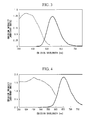
- the optical properties of the first fluorescent material, the second fluorescent material, the third fluorescent material and the fourth fluorescent material synthesized in the above manner are described below. Measurement of these optical properties was conducted using a fluorescence spectrophotometer F-4500 manufactured by Hitachi, Ltd. The spectrophotometer was calibrated by the rhodamine B method using a standard light source, and the measurements were conducted with spectral correction.
- the emission spectrum is shown by the bold line and the excitation spectrum is shown by the narrow line in each case.
- Measurement of the emission spectrum was conducted on the assumption of excitation by the blue light LED, and used an excitation wavelength of 450 nm in each case.
- Measurement of the excitation spectrum was conducted using the light emitting peak wavelength of the respective fluorescent material as the monitored wavelength. Furthermore, emission intensity on the vertical axis was normalized with the peak emission intensity of a reference fluorescent material being set to 1.
- the reference fluorescent material was a commercially available (Y,Gd) 3 Al 5 O 12 :Ce 3+ fluorescent powder (a YAG fluorescent material), and the measured result for the intensity when the excitation wavelength was set to 460 nm, which represents the maximum emission intensity for the reference fluorescent material, was used for the normalization.
- the light emitting peak wavelengths for the fluorescent materials when an excitation wavelength of 450 nm was used were 493 nm for the (Ba,Eu)Si 2 O 2 N 2 fluorescent material of the first fluorescent material, 539 nm for the ⁇ -SiAlON fluorescent material of the second fluorescent material, 589 nm for the ⁇ -SiAlON fluorescent material of the third fluorescent material, and 655 nm for the (Ca,Eu)AlSiN 3 fluorescent material of the fourth fluorescent material.
- the emission colors for the first to fourth fluorescent materials determined by these light emitting peak wavelengths are blue-green for the (Ba,Eu)Si 2 O 2 N 2 fluorescent material of the first fluorescent material, green for the ⁇ -SiAlON fluorescent material of the second fluorescent material, yellow-red for the ⁇ -SiAlON fluorescent material of the third fluorescent material, and red for the (Ca,Eu)AlSiN 3 fluorescent material of the fourth fluorescent material.
- the measured peak emission intensities were 226% for the (Ba,Eu)Si 2 O 2 N 2 fluorescent material of the first fluorescent material, 131% for the ⁇ -SiAlON fluorescent material of the second fluorescent material, 121% for the ⁇ -SiAlON fluorescent material of the third fluorescent material, and 184% for the (Ca,Eu)AlSiN 3 fluorescent material of the fourth fluorescent material.
- FIG. 7 shows a comparison of the light emission spectra for the first to fourth fluorescent materials.
- FIG. 5 shows a chip LED lamp 11.
- a white resin package 19 is formed so as to sandwich two lead wires 12 and 13 therein, and has a concave recess in the center of the package. The ends of the lead wires 12 and 13 are exposed within this concave recess, and a blue LED element 14 having a light emitting peak wavelength of 450 nm is also mounted within the recess.
- the bottom electrode of the blue LED element 14 and the end of the lead wire 12 are connected electrically using a conductive paste.
- top electrode of the blue LED element 14 and the end of the lead wire 13 are connected electrically using a bonding wire 15 formed from a thin gold wire.
- the blue LED element 14 preferably has a light emission central wavelength of 400 to 480 nm, and a light emission central wavelength of 445 to 460 nm is particularly preferred in terms of efficiently exciting the ⁇ -SiAlON fluorescent material of the third fluorescent material and the (Ca,Eu)AlSiN 3 fluorescent material of the fourth fluorescent material.
- this chip LED lamp 11 The production procedure for this chip LED lamp 11 is described below.
- the first fluorescent material, the second fluorescent material, the third fluorescent material and the fourth fluorescent material were weighed and mixed.
- the blue LED element 14 having a light emitting peak wavelength of 450 nm was die bonded to one end of the lead wire 12 using a conductive paste.
- the blue LED element 14 and the other lead wire 13 were wire-bonded using a thin gold wire.
- the resin 17 having 11 % by mass of the mixed fluorescent powder 16 dispersed therein was applied to the concave recess in sufficient quantity to cover the blue LED element 14, and the resin 17 was then cured. At this point, the appropriate application quantity was determined in advance by experimentation.
- the resin used was a silicone resin.
- the mixing ratio between the first fluorescent material that emits a blue-green light, the second fluorescent material that emits a green light, the third fluorescent material that emits a yellow-red light and the fourth fluorescent material that emits a red light was set to a mass ratio of 6:8:7:3, resulting in an emission chromaticity of incandescent lamp color.
- Incandescent lamp color refers to a range, within a CIE 1931 XYZ color space chromaticity diagram, represented by the quadrilateral shape connecting the four points at coordinates (x, y) of (0.4775, 0.4283), (0.4594, 0.3971), (0.4348, 0.4185) and (0.4214, 0.3887).
- the incandescent color LED lamp of this example had an incandescent lamp color with coordinates (x, y) of (0.451, 0.415) in the CIE 1931 XYZ color space chromaticity diagram, and the correlated color temperature was 2870 K.
- the average color rendering index Ra was an extremely high 98.
- the emission efficiency relative to input power was 23 1m/W.
- the emission spectrum is shown in FIG. 6 .
- emission from the blue LED element is dominant for light emission in the wavelength region from 380 to 475 nm
- emission from the first fluorescent material is dominant for light emission in the wavelength region from 475 to 520 nm
- emission from the second fluorescent material is dominant for light emission in the wavelength region from 520 to 560 nm
- emission from the third fluorescent material is dominant for light emission in the wavelength region from 560 to 615 nm
- emission from the fourth fluorescent material is dominant for light emission in the wavelength region from 615 to 780 nm.
- the emission intensities for each of the wavelength regions in the visible light region was 1 : 1.6 : 2.4 : 4.2 : 9.5.
- the mixing ratio of the first to fourth fluorescent materials may require further investigation.
- the first to fourth fluorescent materials used in the present example are still in the process of review and investigation for improved optical properties, and their emission intensities may also be further improved in the future.
- the emission intensities of the fluorescent materials exhibit the relationship shown in FIG. 7 , but if the emission intensity of any of the fluorescent materials is improved in the future, resulting in a change in the proportion of that intensity, then the mixing ratio of the first to fourth fluorescent materials will, of course, also need to be reviewed to ensure that the white LED lamp yields an emission chromaticity of an incandescent lamp color.
- the mixing ratio may be set to a mass ratio of 2.5 ⁇ D / A : 1.9 ⁇ D / B : 1.5 ⁇ D / C : 1.
- the same first fluorescent material that emits a blue-green light, second fluorescent material that emits a green light, third fluorescent material that emits a yellow-red light and fourth fluorescent material that emits a red light as those used in the above Example 1 were used, and the mixing ratio between these first to fourth fluorescent materials was set to a mass ratio of 9:12:8:3, thereby yielding an emission chromaticity with a warm white color.
- the warm white color refers to a range, within a CIE 1931 XYZ color space chromaticity diagram, represented by the quadrilateral shape connecting the four points at coordinates (x, y) of (0.4341, 0.4233), (0.4171, 0.3846), (0.4021, 0.4076) and (0.3903, 0.3719).
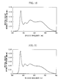
- a warm white LED lamp was prepared in the same manner as Example 1, and the emission spectrum of the lamp was measured.
- the warm white LED lamp of this example had a warm white color with coordinates (x, y) of (0.413, 0.397) in the CIE 1931 XYZ color space chromaticity diagram, and the correlated color temperature was 3500 K.
- the average color rendering index Ra was 96, an extremely high value similar to that observed for the incandescent lamp color of Example 1.
- the emission efficiency relative to input power was 25 1m/W.
- the emission spectrum is shown in FIG. 8 .
- emission from the blue LED element is dominant for light emission in the wavelength region from 380 to 475 nm
- emission from the first fluorescent material is dominant for light emission in the wavelength region from 475 to 520 nm
- emission from the second fluorescent material is dominant for light emission in the wavelength region from 520 to 560 nm
- emission from the third fluorescent material is dominant for light emission in the wavelength region from 560 to 615 nm
- emission from the fourth fluorescent material is dominant for light emission in the wavelength region from 615 to 780 nm.
- the emission intensities for each of the wavelength regions in the visible light region was 1 : 1.0 : 1.5 : 2.3 : 4.6.
- the mixing ratio of the first to fourth fluorescent materials may require further investigation.
- the first to fourth fluorescent materials used in the present example are still in the process of review and investigation for improved optical properties, and their emission intensities may also be further improved in the future.
- the emission intensities of the fluorescent materials exhibit the relationship shown in FIG. 7 , but if the emission intensity of any of the fluorescent materials is improved in the future, resulting in a change in the proportion of that intensity, then the mixing ratio of the first to fourth fluorescent materials will, of course, also need to be reviewed to ensure that the white LED lamp yields an emission chromaticity of a warm white color.
- the mixing ratio may be set to a mass ratio of 3.7 ⁇ D / A : 12.8 ⁇ D / B : 1.8 ⁇ D / C : 1.
- the same first fluorescent material that emits a blue-green light, second fluorescent material that emits a green light, third fluorescent material that emits a yellow-red light and fourth fluorescent material that emits a red light as those used in the above Example 1 were used, and the mixing ratio between these first to fourth fluorescent materials was set to a mass ratio of 4.5:5:3:1, thereby yielding an emission chromaticity with a white color.
- the white color refers to a range, within a CIE 1931 XYZ color space chromaticity diagram, represented by the quadrilateral shape connecting the four points at coordinates (x, y) of (0.3938, 0.4097), (0.3805, 0.3642), (0.3656, 0.3905) and (0.3584, 0.3499).
- a white LED lamp was prepared in the same manner as Example 1, and the emission spectrum of the lamp was measured.
- the white LED lamp of this example had a white color with coordinates (x, y) of (0.376, 0.378) in the CIE 1931 XYZ color space chromaticity diagram, and the correlated color temperature was 4130 K.
- the average color rendering index Ra was 95, an extremely high value similar to that observed for the incandescent lamp color of Example 1.
- the emission efficiency relative to input power was 27 1m/W.
- the emission spectrum is shown in FIG. 9 .
- emission from the blue LED element is dominant for light emission in the wavelength region from 380 to 475 nm
- emission from the first fluorescent material is dominant for light emission in the wavelength region from 475 to 520 nm
- emission from the second fluorescent material is dominant for light emission in the wavelength region from 520 to 560 nm
- emission from the third fluorescent material is dominant for light emission in the wavelength region from 560 to 615 nm
- emission from the fourth fluorescent material is dominant for light emission in the wavelength region from 615 to 780 nm.
- the emission intensities for each of the wavelength regions in the visible light region was 1 : 0.8 : 1.2 : 1.6 : 2.9.
- the mixing ratio of the first to fourth fluorescent materials may require further investigation.
- the first to fourth fluorescent materials used in the present example are still in the process of review and investigation for improved optical properties, and their emission intensities may also be further improved in the future.
- the emission intensities of the fluorescent materials exhibit the relationship shown in FIG. 7 , but if the emission intensity of any of the fluorescent materials is improved in the future, resulting in a change in the proportion of that intensity, then the mixing ratio of the first to fourth fluorescent materials will, of course, also need to be reviewed to ensure that the white LED lamp yields an emission chromaticity of white color.
- the mixing ratio may be set to a mass ratio of (5.5 ⁇ D/A):(3.6 ⁇ D/B):(2.0 ⁇ D/C):1.
- the same first fluorescent material that emits a blue-green light, second fluorescent material that emits a green light, third fluorescent material that emits a yellow-red light and fourth fluorescent material that emits a red light as those used in the above Example 1 were used, and the mixing ratio between these first to fourth fluorescent materials was set to a mass ratio of 6:7:3.5:1, thereby yielding an emission chromaticity with a neutral white color.
- the neutral white color refers to a range, within a CIE 1931 XYZ color space chromaticity diagram, represented by the quadrilateral shape connecting the four points at coordinates (x, y) of (0.3616, 0.3875), (0.3552, 0.3476), (0.3353, 0.3659) and (0.3345, 0.3314).
- a neutral white LED lamp was prepared in the same manner as Example 1, and the emission spectrum of the lamp was measured.
- the neutral white LED lamp of this example had a neutral white color with coordinates (x, y) of (0.343, 0.353) in the CIE 1931 XYZ color space chromaticity diagram, and the correlated color temperature was 5380 K.
- the average color rendering index Ra was 96, an extremely high value similar to that observed for the incandescent lamp color of Example 1.
- the emission efficiency relative to input power was 29 1m/W.
- the emission spectrum is shown in FIG. 10 .
- emission from the blue LED element is dominant for light emission in the wavelength region from 380 to 475 nm
- emission from the first fluorescent material is dominant for light emission in the wavelength region from 475 to 520 nm
- emission from the second fluorescent material is dominant for light emission in the wavelength region from 520 to 560 nm
- emission from the third fluorescent material is dominant for light emission in the wavelength region from 560 to 615 nm
- emission from the fourth fluorescent material is dominant for light emission in the wavelength region from 615 to 780 nm.
- the emission intensities for each of the wavelength regions in the visible light region was 1 : 0.8 : 0.9 : 1.1 : 1.7.
- the mixing ratio of the first to fourth fluorescent materials may require further investigation.
- the first to fourth fluorescent materials used in the present example are still in the process of review and investigation for improved optical properties, and their emission intensities may also be further improved in the future.
- the emission intensities of the fluorescent materials exhibit the relationship shown in FIG. 7 , but if the emission intensity of any of the fluorescent materials is improved in the future, resulting in a change in the proportion of that intensity, then the mixing ratio of the first to fourth fluorescent materials will, of course, also need to be reviewed to ensure that the white LED lamp yields an emission chromaticity of a neutral white color.
- the mixing ratio may be set to a mass ratio of (7.4 ⁇ D/A):(5.0 ⁇ D/B):(2.3 ⁇ D/C):1.
- the same first fluorescent material that emits a blue-green light, second fluorescent material that emits a green light, third fluorescent material that emits a yellow-red light and fourth fluorescent material that emits a red light as those used in the above Example 1 were used, and the mixing ratio between these first to fourth fluorescent materials was set to a mass ratio of 8:9:4:1, thereby yielding an emission chromaticity with a daylight color.
- the daylight color refers to a range, within a CIE 1931 XYZ color space chromaticity diagram, represented by the quadrilateral shape connecting the four points at coordinates (x, y) of (0.3274, 0.3673), (0.3282, 0.3297), (0.2998, 0.3396) and (0.3064, 0.3091).
- a daylight color LED lamp was prepared in the same manner as Example 1, and the emission spectrum of the lamp was measured.
- the daylight color LED lamp of this example had a white color with coordinates (x, y) of (0.311, 0.328) in the CIE 1931 XYZ color space chromaticity diagram, and the correlated color temperature was 6630 K.
- the average color rendering index Ra was 96, an extremely high value similar to that observed for the incandescent lamp color of Example 1.
- the emission efficiency relative to input power was 31 1m/W.
- the emission spectrum is shown in FIG. 11 .
- emission from the blue LED element is dominant for light emission in the wavelength region from 380 to 475 nm
- emission from the first fluorescent material is dominant for light emission in the wavelength region from 475 to 520 nm
- emission from the second fluorescent material is dominant for light emission in the wavelength region from 520 to 560 nm
- emission from the third fluorescent material is dominant for light emission in the wavelength region from 560 to 615 nm
- emission from the fourth fluorescent material is dominant for light emission in the wavelength region from 615 to 780 nm.
- the emission intensities for each of the wavelength regions in the visible light region was 1 : 0.7 : 0.7 : 0.9 : 1.1.
- the mixing ratio of the first to fourth fluorescent materials may require further investigation.
- the first to fourth fluorescent materials used in the present example are still in the process of review and investigation for improved optical properties, and their emission intensities may also be further improved in the future.
- the emission intensities of the fluorescent materials exhibit the relationship shown in FIG. 7 , but if the emission intensity of any of the fluorescent materials is improved in the future, resulting in a change in the proportion of that intensity, then the mixing ratio of the first to fourth fluorescent materials will, of course, also need to be reviewed to ensure that the white LED lamp yields an emission chromaticity of a daylight color.
- the mixing ratio may be set to a mass ratio of 9.8 ⁇ D / A : 6.4 ⁇ D / B : 2.6 ⁇ D / C : 1.
- the light emitting device of the present invention is able to provide a white LED lamp and an illumination device that exhibit high levels of reliability, high efficiency, and an extremely high color rendering characteristic. Accordingly, the present invention is extremely useful industrially.
Landscapes
- Chemical & Material Sciences (AREA)
- Inorganic Chemistry (AREA)
- Engineering & Computer Science (AREA)
- Materials Engineering (AREA)
- Organic Chemistry (AREA)
- Led Device Packages (AREA)
- Luminescent Compositions (AREA)
Applications Claiming Priority (2)
| Application Number | Priority Date | Filing Date | Title |
|---|---|---|---|
| JP2006221062 | 2006-08-14 | ||
| PCT/JP2007/064861 WO2008020541A1 (fr) | 2006-08-14 | 2007-07-30 | Dispositif électroluminescent et dispositif d'éclairage |
Publications (3)
| Publication Number | Publication Date |
|---|---|
| EP2056366A1 true EP2056366A1 (fr) | 2009-05-06 |
| EP2056366A4 EP2056366A4 (fr) | 2011-05-25 |
| EP2056366B1 EP2056366B1 (fr) | 2013-04-03 |
Family
ID=39082067
Family Applications (1)
| Application Number | Title | Priority Date | Filing Date |
|---|---|---|---|
| EP07805885A Ceased EP2056366B1 (fr) | 2006-08-14 | 2007-07-30 | Dispositif électroluminescent et dispositif d'éclairage |
Country Status (7)
| Country | Link |
|---|---|
| US (1) | US8053970B2 (fr) |
| EP (1) | EP2056366B1 (fr) |
| JP (1) | JP4963705B2 (fr) |
| KR (1) | KR101108975B1 (fr) |
| CN (1) | CN101501874B (fr) |
| TW (1) | TWI364853B (fr) |
| WO (1) | WO2008020541A1 (fr) |
Cited By (5)
| Publication number | Priority date | Publication date | Assignee | Title |
|---|---|---|---|---|
| CN103642492A (zh) * | 2013-12-23 | 2014-03-19 | 厦门大学 | 一种硅基氮氧化物荧光粉的制备方法 |
| EP2824721A1 (fr) * | 2013-07-12 | 2015-01-14 | LG Innotek Co., Ltd. | Dispositif électroluminescent |
| EP2549555A3 (fr) * | 2011-04-29 | 2015-11-04 | Samsung Electronics Co., Ltd. | Dispositif électroluminescent blanc, appareil d'affichage et appareil d'éclairage |
| EP3054490A4 (fr) * | 2013-10-02 | 2017-07-19 | Glbtech Co. Ltd. | Dispositif émetteur de lumière blanche à rendu de couleur élevé |
| KR20180122244A (ko) * | 2017-05-02 | 2018-11-12 | 삼성전자주식회사 | 백색 발광장치 및 조명 장치 |
Families Citing this family (62)
| Publication number | Priority date | Publication date | Assignee | Title |
|---|---|---|---|---|
| KR100944085B1 (ko) | 2008-06-23 | 2010-02-24 | 서울반도체 주식회사 | 발광 장치 |
| WO2010018999A2 (fr) * | 2008-08-12 | 2010-02-18 | 삼성전기주식회사 | Procédé de production d’un phosphore β-sialon |
| US8158026B2 (en) | 2008-08-12 | 2012-04-17 | Samsung Led Co., Ltd. | Method for preparing B-Sialon phosphor |
| WO2011019191A2 (fr) * | 2009-08-10 | 2011-02-17 | 엘지이노텍주식회사 | Phosphore, procédé de préparation correspondant et dispositif émettant de la lumière blanche |
| KR101172143B1 (ko) * | 2009-08-10 | 2012-08-07 | 엘지이노텍 주식회사 | 백색 발광다이오드 소자용 시온계 산화질화물 형광체, 그의 제조방법 및 그를 이용한 백색 led 소자 |
| WO2011024818A1 (fr) | 2009-08-26 | 2011-03-03 | 三菱化学株式会社 | Dispositif émettant de la lumière blanche à semi-conducteur |
| KR101163902B1 (ko) * | 2010-08-10 | 2012-07-09 | 엘지이노텍 주식회사 | 발광 소자 |
| WO2011028033A2 (fr) | 2009-09-02 | 2011-03-10 | 엘지이노텍주식회사 | Phosphore, procédé de préparation de phosphore, et dispositif émettant de la lumière blanche |
| CN101760190B (zh) * | 2009-10-30 | 2013-07-03 | 彩虹集团公司 | 一种合成稀土掺杂氮氧化物荧光粉及其制备方法 |
| KR101144754B1 (ko) * | 2010-01-19 | 2012-05-09 | 일진반도체 주식회사 | 백색 발광장치 및 이의 제조방법 |
| EP2546897B1 (fr) * | 2010-03-12 | 2019-01-23 | Kabushiki Kaisha Toshiba | Dispositif d'éclairage à lumière blanche |
| TW201138159A (en) * | 2010-04-22 | 2011-11-01 | shi-long Liu | Light emitting diode package structure and its manufacturing method |
| KR101261461B1 (ko) * | 2010-07-14 | 2013-05-10 | 엘지이노텍 주식회사 | 액정 표시 장치 |
| TWI457418B (zh) * | 2010-09-29 | 2014-10-21 | 友達光電股份有限公司 | 白光發光二極體裝置、發光裝置及液晶顯示器 |
| JP5676653B2 (ja) | 2011-01-18 | 2015-02-25 | シャープ株式会社 | 半導体発光装置 |
| CN102796522A (zh) * | 2011-05-27 | 2012-11-28 | 亿广科技(上海)有限公司 | 荧光粉组合物及使用该荧光粉组合物的白色发光装置 |
| WO2012165524A1 (fr) | 2011-06-03 | 2012-12-06 | 三菱化学株式会社 | Dispositif électroluminescent semi-conducteur, dispositif d'éclairage par irradiation d'objet exposé, dispositif d'éclairage par irradiation de viande, dispositif d'éclairage par irradiation de légumes, dispositif d'éclairage par irradiation de poisson frais, dispositif d'éclairage d'usage général et système électroluminescent semi-conducteur |
| JP5937837B2 (ja) * | 2012-02-09 | 2016-06-22 | デンカ株式会社 | 蛍光体及び発光装置 |
| JP5916411B2 (ja) * | 2012-02-09 | 2016-05-11 | デンカ株式会社 | 蛍光体及び発光装置 |
| WO2013125521A1 (fr) * | 2012-02-20 | 2013-08-29 | シャープ株式会社 | Dispositif d'éclairage |
| JP5749201B2 (ja) * | 2012-03-09 | 2015-07-15 | 株式会社東芝 | 白色発光装置 |
| KR101402540B1 (ko) * | 2013-01-23 | 2014-06-02 | 주식회사 효성 | 형광체 조성물 및 이를 포함하는 발광장치 |
| EP2765175A3 (fr) * | 2013-02-07 | 2014-09-03 | Everlight Electronics Co., Ltd | Compositions phosphorique pour dispositifs électroluminescents blancs à haute fiabilité |
| KR101706600B1 (ko) * | 2014-06-13 | 2017-02-16 | 지엘비텍 주식회사 | 고연색성 백색 발광 소자 |
| WO2015057370A1 (fr) | 2013-10-14 | 2015-04-23 | United Technologies Corporation | Procédé de détection d'une qualité de conversion d'un matériau composite matriciel écologique et système pour celui-ci |
| US9837585B2 (en) | 2013-11-08 | 2017-12-05 | Lumimicro Corp. Ltd. | Light emitting device |
| WO2015068916A1 (fr) * | 2013-11-08 | 2015-05-14 | 루미마이크로 주식회사 | Dispositif électroluminescent |
| WO2015072599A1 (fr) * | 2013-11-14 | 2015-05-21 | 안종욱 | Dispositif pour éclairage d'émission de lumière blanche à rendu des couleurs ultra-élevé utilisant une source de lumière bleue et des phosphores bleus |
| US20150184813A1 (en) * | 2013-12-31 | 2015-07-02 | Xicato, Inc. | Efficient led-based illumination modules with high color rendering index |
| CN103881703B (zh) * | 2014-03-25 | 2016-04-06 | 陕西科技大学 | 一种白光led用单一基质荧光粉的制备方法 |
| KR101476217B1 (ko) * | 2014-05-28 | 2014-12-24 | 엘지전자 주식회사 | 황색 발광 형광체 및 이를 이용한 발광 소자 패키지 |
| KR101467808B1 (ko) | 2014-07-14 | 2014-12-03 | 엘지전자 주식회사 | 황색 발광 형광체 및 이를 이용한 발광 소자 패키지 |
| CN104263359B (zh) * | 2014-09-12 | 2016-10-05 | 江门市科恒实业股份有限公司 | 一种全光谱led荧光粉及其应用 |
| WO2016056836A1 (fr) * | 2014-10-07 | 2016-04-14 | 서울반도체 주식회사 | Dispositif électroluminescent |
| KR102100193B1 (ko) * | 2014-11-10 | 2020-04-13 | 엘지전자 주식회사 | 발광 장치 |
| KR101651342B1 (ko) * | 2014-12-03 | 2016-08-26 | 주식회사 올릭스 | 미술 조명용 스펙트럼 특성을 만족하는 발광 다이오드 소자 및 모듈 |
| JP6384302B2 (ja) * | 2014-12-05 | 2018-09-05 | 日亜化学工業株式会社 | 発光装置 |
| KR102423748B1 (ko) * | 2015-07-08 | 2022-07-22 | 쑤저우 레킨 세미컨덕터 컴퍼니 리미티드 | 발광장치 |
| KR20170029234A (ko) * | 2015-09-07 | 2017-03-15 | 엘지전자 주식회사 | 발광 장치 |
| KR101652258B1 (ko) * | 2015-09-10 | 2016-08-31 | 지엘비텍 주식회사 | 고연색성 백색 발광 소자 |
| JP6585521B2 (ja) * | 2016-02-16 | 2019-10-02 | 東芝メモリ株式会社 | テンプレート、インプリント方法およびインプリント装置 |
| JP6460040B2 (ja) * | 2016-03-04 | 2019-01-30 | 日亜化学工業株式会社 | 発光装置 |
| US10256374B2 (en) | 2016-03-04 | 2019-04-09 | Nichia Corporation | Light emitting device |
| US10236425B2 (en) * | 2016-03-08 | 2019-03-19 | Glbtech Co., Ltd. | White light emitting device having high color rendering |
| CN105870303B (zh) * | 2016-04-18 | 2020-08-28 | 佛山市中昊光电科技有限公司 | 一种全光谱的led光源 |
| JP6477779B2 (ja) * | 2016-05-26 | 2019-03-06 | 日亜化学工業株式会社 | 発光装置 |
| CN107565004B (zh) * | 2016-06-07 | 2020-06-30 | 青岛云源光电科技有限公司 | 一种led面光源高显指发光的封装方法 |
| KR102560889B1 (ko) * | 2016-07-29 | 2023-07-31 | 쑤저우 레킨 세미컨덕터 컴퍼니 리미티드 | 발광소자 패키지 및 조명장치 |
| US10270015B1 (en) | 2017-01-13 | 2019-04-23 | Nichia Corporation | Light-emitting device |
| KR101809098B1 (ko) * | 2017-08-14 | 2018-01-18 | 루미마이크로 주식회사 | 발광장치 |
| CN107565006B (zh) * | 2017-08-30 | 2021-05-18 | 合肥工业大学 | 一种具有日光可见光部分光谱结构的led光源及灯具 |
| CN108091751B (zh) * | 2017-12-06 | 2020-02-18 | 佛山市国星光电股份有限公司 | 一种白光led器件及其制备方法、led灯 |
| CN113178437B (zh) * | 2017-12-21 | 2023-08-11 | 厦门市三安光电科技有限公司 | 一种白光led封装结构以及白光源系统 |
| KR102130817B1 (ko) * | 2018-01-25 | 2020-07-08 | 지엘비텍 주식회사 | 고연색성 백색 발광 소자 |
| CN108732818A (zh) * | 2018-05-29 | 2018-11-02 | 武汉华星光电技术有限公司 | 背光模组、显示装置及背光模组的制作方法 |
| CN108828888A (zh) * | 2018-06-27 | 2018-11-16 | 朗昭创新控股(深圳)有限公司 | 一种投影设备 |
| CN108638707A (zh) * | 2018-06-27 | 2018-10-12 | 朗昭创新控股(深圳)有限公司 | 一种发光黑板 |
| JP7224983B2 (ja) * | 2019-03-19 | 2023-02-20 | スタンレー電気株式会社 | 半導体発光装置及び半導体発光モジュール |
| CN110098304B (zh) * | 2019-04-29 | 2021-02-02 | 佛山市国星光电股份有限公司 | 一种新型发光灯珠与灯具 |
| JP7815946B2 (ja) * | 2022-04-05 | 2026-02-18 | Toppanホールディングス株式会社 | 表示装置および波長変換基板 |
| CN114806550A (zh) * | 2022-05-18 | 2022-07-29 | 龙岩学院 | 一种红色氮化物荧光材料及其制备方法 |
| CN117393549B (zh) * | 2023-09-18 | 2025-01-10 | 旭宇光电(深圳)股份有限公司 | 一种高光效全光谱半导体发光装置 |
Family Cites Families (18)
| Publication number | Priority date | Publication date | Assignee | Title |
|---|---|---|---|---|
| JP2927279B2 (ja) | 1996-07-29 | 1999-07-28 | 日亜化学工業株式会社 | 発光ダイオード |
| JPH10163535A (ja) | 1996-11-27 | 1998-06-19 | Kasei Optonix Co Ltd | 白色発光素子 |
| DE59814117D1 (de) | 1997-03-03 | 2007-12-20 | Philips Intellectual Property | Weisse lumineszenzdiode |
| JP2900928B2 (ja) | 1997-10-20 | 1999-06-02 | 日亜化学工業株式会社 | 発光ダイオード |
| US6680569B2 (en) | 1999-02-18 | 2004-01-20 | Lumileds Lighting U.S. Llc | Red-deficiency compensating phosphor light emitting device |
| US6621211B1 (en) * | 2000-05-15 | 2003-09-16 | General Electric Company | White light emitting phosphor blends for LED devices |
| JP3668770B2 (ja) | 2001-06-07 | 2005-07-06 | 独立行政法人物質・材料研究機構 | 希土類元素を付活させた酸窒化物蛍光体 |
| DE10133352A1 (de) * | 2001-07-16 | 2003-02-06 | Patent Treuhand Ges Fuer Elektrische Gluehlampen Mbh | Beleuchtungseinheit mit mindestens einer LED als Lichtquelle |
| JP2003321675A (ja) | 2002-04-26 | 2003-11-14 | Nichia Chem Ind Ltd | 窒化物蛍光体及びその製造方法 |
| WO2004042834A1 (fr) * | 2002-11-08 | 2004-05-21 | Nichia Corporation | Dispositif electroluminescent, phosphore et procede de preparation dudit phosphore |
| US7088038B2 (en) * | 2003-07-02 | 2006-08-08 | Gelcore Llc | Green phosphor for general illumination applications |
| JP3921545B2 (ja) * | 2004-03-12 | 2007-05-30 | 独立行政法人物質・材料研究機構 | 蛍光体とその製造方法 |
| JP2005285800A (ja) * | 2004-03-26 | 2005-10-13 | Kyocera Corp | 発光装置 |
| JP4543250B2 (ja) * | 2004-08-27 | 2010-09-15 | Dowaエレクトロニクス株式会社 | 蛍光体混合物および発光装置 |
| JP4729281B2 (ja) * | 2004-09-13 | 2011-07-20 | 株式会社フジクラ | 発光ダイオード及び発光ダイオード製造方法 |
| JP4798335B2 (ja) * | 2004-12-20 | 2011-10-19 | Dowaエレクトロニクス株式会社 | 蛍光体および蛍光体を用いた光源 |
| JP2006221062A (ja) | 2005-02-14 | 2006-08-24 | Canon Inc | 積層型回折光学素子の製造方法及び積層型回折光学素子 |
| JP2007180377A (ja) * | 2005-12-28 | 2007-07-12 | Sharp Corp | 発光装置 |
-
2007
- 2007-07-30 WO PCT/JP2007/064861 patent/WO2008020541A1/fr not_active Ceased
- 2007-07-30 KR KR1020097002842A patent/KR101108975B1/ko not_active Expired - Fee Related
- 2007-07-30 TW TW096127803A patent/TWI364853B/zh not_active IP Right Cessation
- 2007-07-30 EP EP07805885A patent/EP2056366B1/fr not_active Ceased
- 2007-07-30 CN CN2007800297571A patent/CN101501874B/zh active Active
- 2007-07-30 JP JP2008529840A patent/JP4963705B2/ja active Active
-
2009
- 2009-02-11 US US12/369,351 patent/US8053970B2/en active Active
Cited By (11)
| Publication number | Priority date | Publication date | Assignee | Title |
|---|---|---|---|---|
| EP2549555A3 (fr) * | 2011-04-29 | 2015-11-04 | Samsung Electronics Co., Ltd. | Dispositif électroluminescent blanc, appareil d'affichage et appareil d'éclairage |
| EP2824721A1 (fr) * | 2013-07-12 | 2015-01-14 | LG Innotek Co., Ltd. | Dispositif électroluminescent |
| US9318668B2 (en) | 2013-07-12 | 2016-04-19 | Lg Innotek Co., Ltd. | Phosphor and light emitting device having the same |
| EP3054490A4 (fr) * | 2013-10-02 | 2017-07-19 | Glbtech Co. Ltd. | Dispositif émetteur de lumière blanche à rendu de couleur élevé |
| US10020428B2 (en) | 2013-10-02 | 2018-07-10 | Glbtech Co., Ltd. | White light emitting device having high color rendering |
| EP3557635A1 (fr) * | 2013-10-02 | 2019-10-23 | Glbtech Co. Ltd. | Dispositif émetteur de lumière blanche à rendu de couleur élevé |
| CN103642492A (zh) * | 2013-12-23 | 2014-03-19 | 厦门大学 | 一种硅基氮氧化物荧光粉的制备方法 |
| CN103642492B (zh) * | 2013-12-23 | 2016-01-20 | 厦门大学 | 一种硅基氮氧化物荧光粉的制备方法 |
| KR20180122244A (ko) * | 2017-05-02 | 2018-11-12 | 삼성전자주식회사 | 백색 발광장치 및 조명 장치 |
| EP3425023A1 (fr) * | 2017-05-02 | 2019-01-09 | Samsung Electronics Co., Ltd. | Dispositifs électroluminescents blancs |
| US10312419B2 (en) | 2017-05-02 | 2019-06-04 | Samsung Electronics Co., Ltd. | White light emitting devices |
Also Published As
| Publication number | Publication date |
|---|---|
| KR101108975B1 (ko) | 2012-05-30 |
| JP4963705B2 (ja) | 2012-06-27 |
| US20090146549A1 (en) | 2009-06-11 |
| EP2056366A4 (fr) | 2011-05-25 |
| CN101501874A (zh) | 2009-08-05 |
| KR20090048589A (ko) | 2009-05-14 |
| TW200818553A (en) | 2008-04-16 |
| WO2008020541A1 (fr) | 2008-02-21 |
| JPWO2008020541A1 (ja) | 2010-01-07 |
| CN101501874B (zh) | 2012-04-04 |
| TWI364853B (en) | 2012-05-21 |
| US8053970B2 (en) | 2011-11-08 |
| EP2056366B1 (fr) | 2013-04-03 |
Similar Documents
| Publication | Publication Date | Title |
|---|---|---|
| US8053970B2 (en) | Light emitting device and illumination device | |
| EP1710291B1 (fr) | Dispositif électroluminescent et appareil d'éclairage | |
| EP1734096B1 (fr) | Dispositif d'emission de lumiere et dispositif d'eclairage | |
| US8709838B2 (en) | Method for preparing a β-SiAlON phosphor | |
| EP1449264B1 (fr) | Materiau photoluminescent pour diodes electroluminescentes, et diode electroluminescente | |
| EP1780255B1 (fr) | Substance fluorescente et lampe à diode électroluminescente colorée pour ampoule électrique utilisant la substance fluorescente et émettant la lumière colorée pour ampoule électrique | |
| CN102216421B (zh) | 制备β-SiAlON磷光体的方法 | |
| JPWO2006121083A1 (ja) | β型サイアロン蛍光体 | |
| EP1736525B1 (fr) | Luminophore a base d´oxynitrure et dispositif d´emission de lumiere | |
| WO2013105346A1 (fr) | Corps fluorescent et dispositif électroluminescent | |
| CN101668829B (zh) | 赛隆荧光体 | |
| WO2006061778A1 (fr) | Systeme d'eclairage comprenant une source de rayonnement et un phosphore a emission de bleu | |
| US11898080B2 (en) | Phosphor, method for producing same and light emitting element |
Legal Events
| Date | Code | Title | Description |
|---|---|---|---|
| PUAI | Public reference made under article 153(3) epc to a published international application that has entered the european phase |
Free format text: ORIGINAL CODE: 0009012 |
|
| 17P | Request for examination filed |
Effective date: 20090310 |
|
| AK | Designated contracting states |
Kind code of ref document: A1 Designated state(s): AT BE BG CH CY CZ DE DK EE ES FI FR GB GR HU IE IS IT LI LT LU LV MC MT NL PL PT RO SE SI SK TR |
|
| AX | Request for extension of the european patent |
Extension state: AL BA HR MK RS |
|
| RBV | Designated contracting states (corrected) |
Designated state(s): DE NL |
|
| A4 | Supplementary search report drawn up and despatched |
Effective date: 20110427 |
|
| 17Q | First examination report despatched |
Effective date: 20120118 |
|
| DAX | Request for extension of the european patent (deleted) | ||
| GRAP | Despatch of communication of intention to grant a patent |
Free format text: ORIGINAL CODE: EPIDOSNIGR1 |
|
| GRAS | Grant fee paid |
Free format text: ORIGINAL CODE: EPIDOSNIGR3 |
|
| GRAA | (expected) grant |
Free format text: ORIGINAL CODE: 0009210 |
|
| RAP1 | Party data changed (applicant data changed or rights of an application transferred) |
Owner name: NATIONAL INSTITUTE FOR MATERIALS SCIENCE Owner name: FUJIKURA LTD. |
|
| AK | Designated contracting states |
Kind code of ref document: B1 Designated state(s): DE NL |
|
| REG | Reference to a national code |
Ref country code: DE Ref legal event code: R096 Ref document number: 602007029491 Country of ref document: DE Effective date: 20130529 |
|
| REG | Reference to a national code |
Ref country code: NL Ref legal event code: T3 |
|
| PLBE | No opposition filed within time limit |
Free format text: ORIGINAL CODE: 0009261 |
|
| STAA | Information on the status of an ep patent application or granted ep patent |
Free format text: STATUS: NO OPPOSITION FILED WITHIN TIME LIMIT |
|
| 26N | No opposition filed |
Effective date: 20140106 |
|
| REG | Reference to a national code |
Ref country code: DE Ref legal event code: R097 Ref document number: 602007029491 Country of ref document: DE Effective date: 20140106 |
|
| PGFP | Annual fee paid to national office [announced via postgrant information from national office to epo] |
Ref country code: NL Payment date: 20160610 Year of fee payment: 10 |
|
| REG | Reference to a national code |
Ref country code: DE Ref legal event code: R082 Ref document number: 602007029491 Country of ref document: DE Representative=s name: LEINWEBER & ZIMMERMANN PATENTANWALTS-PARTG MBB, DE Ref country code: DE Ref legal event code: R082 Ref document number: 602007029491 Country of ref document: DE Representative=s name: LEINWEBER & ZIMMERMANN, DE Ref country code: DE Ref legal event code: R081 Ref document number: 602007029491 Country of ref document: DE Owner name: NATIONAL INSTITUTE FOR MATERIALS SCIENCE, TSUK, JP Free format text: FORMER OWNERS: FUJIKURA LTD., TOKIO/TOKYO, JP; NATIONAL INSTITUTE FOR MATERIALS SCIENCE, TSUKUBA, IBARAKI, JP |
|
| REG | Reference to a national code |
Ref country code: NL Ref legal event code: MM Effective date: 20170801 |
|
| PG25 | Lapsed in a contracting state [announced via postgrant information from national office to epo] |
Ref country code: NL Free format text: LAPSE BECAUSE OF NON-PAYMENT OF DUE FEES Effective date: 20170801 |
|
| P01 | Opt-out of the competence of the unified patent court (upc) registered |
Effective date: 20230526 |
|
| PGFP | Annual fee paid to national office [announced via postgrant information from national office to epo] |
Ref country code: DE Payment date: 20240604 Year of fee payment: 18 |
|
| REG | Reference to a national code |
Ref country code: DE Ref legal event code: R079 Ref document number: 602007029491 Country of ref document: DE Free format text: PREVIOUS MAIN CLASS: H01L0033000000 Ipc: H10H0020000000 |
|
| REG | Reference to a national code |
Ref country code: DE Ref legal event code: R119 Ref document number: 602007029491 Country of ref document: DE |
|
| PG25 | Lapsed in a contracting state [announced via postgrant information from national office to epo] |
Ref country code: DE Free format text: LAPSE BECAUSE OF NON-PAYMENT OF DUE FEES Effective date: 20260203 |