EP2056410B1 - Un connecteur électrique - Google Patents
Un connecteur électrique Download PDFInfo
- Publication number
- EP2056410B1 EP2056410B1 EP08018752.9A EP08018752A EP2056410B1 EP 2056410 B1 EP2056410 B1 EP 2056410B1 EP 08018752 A EP08018752 A EP 08018752A EP 2056410 B1 EP2056410 B1 EP 2056410B1
- Authority
- EP
- European Patent Office
- Prior art keywords
- press
- hole
- angle
- connector according
- projections
- Prior art date
- Legal status (The legal status is an assumption and is not a legal conclusion. Google has not performed a legal analysis and makes no representation as to the accuracy of the status listed.)
- Ceased
Links
Images



Classifications
-
- H—ELECTRICITY
- H01—ELECTRIC ELEMENTS
- H01R—ELECTRICALLY-CONDUCTIVE CONNECTIONS; STRUCTURAL ASSOCIATIONS OF A PLURALITY OF MUTUALLY-INSULATED ELECTRICAL CONNECTING ELEMENTS; COUPLING DEVICES; CURRENT COLLECTORS
- H01R13/00—Details of coupling devices of the kinds covered by groups H01R12/70 or H01R24/00 - H01R33/00
- H01R13/02—Contact members
- H01R13/10—Sockets for co-operation with pins or blades
-
- H—ELECTRICITY
- H01—ELECTRIC ELEMENTS
- H01R—ELECTRICALLY-CONDUCTIVE CONNECTIONS; STRUCTURAL ASSOCIATIONS OF A PLURALITY OF MUTUALLY-INSULATED ELECTRICAL CONNECTING ELEMENTS; COUPLING DEVICES; CURRENT COLLECTORS
- H01R13/00—Details of coupling devices of the kinds covered by groups H01R12/70 or H01R24/00 - H01R33/00
- H01R13/40—Securing contact members in or to a base or case; Insulating of contact members
- H01R13/405—Securing in non-demountable manner, e.g. moulding, riveting
- H01R13/41—Securing in non-demountable manner, e.g. moulding, riveting by frictional grip in grommet, panel or base
-
- H—ELECTRICITY
- H01—ELECTRIC ELEMENTS
- H01R—ELECTRICALLY-CONDUCTIVE CONNECTIONS; STRUCTURAL ASSOCIATIONS OF A PLURALITY OF MUTUALLY-INSULATED ELECTRICAL CONNECTING ELEMENTS; COUPLING DEVICES; CURRENT COLLECTORS
- H01R13/00—Details of coupling devices of the kinds covered by groups H01R12/70 or H01R24/00 - H01R33/00
- H01R13/02—Contact members
- H01R13/04—Pins or blades for co-operation with sockets
Definitions
- the present invention relates to a connector.
- Japanese Unexamined Patent Publication No. 2006-19228 discloses a connector in which press-in holes are formed to penetrate a retaining wall of a housing made of synthetic resin and tab-shaped terminals are pressed into these press-in holes.
- Each tab-shaped terminal includes a narrow and long tab-shaped contact portion at the leading end and a press-in portion wider than the press-in hole and continuous with the rear end of the tab-shaped contact portion. The tab-shaped terminal is pressed into the press-in hole with the tab-shaped contact portion in the lead, and the press-in portion deforms the inner wall portion of the press-in hole to widen the width of the press-in hole in a press-in process.
- reaction force acts on the press-in portion from the inner wall portion of the press-in hole being deformed and becomes press-in resistance. Since the width of the press-in hole is constant over the entire length in the above conventional connector, constant press-in resistance continues to act from the start to the end of the press-in process.
- the press-in resistance is decreased by making a difference in width between the press-in hole and the press-in portion smaller, a force for retaining the tab-shaped terminal is reduced in a state where the press-in process is completed, wherefore the press-in resistance cannot be reduced.
- U.S. patent application publication US 2005/70159038 A1 discloses a connector having a housing with insertion holes and terminal fittings to be pressed into the insertion holes.
- Each terminal fitting has a press-in portion to be pressed into the insertion hole while pushing material of the housing outward.
- An accommodating portion is continuous with the press-in portion and has slanted surfaces narrowing the press-in portion toward the rear side with respect to the inserting direction. The width between the rear ends of the slanted surfaces of the accommodating portion is equal to or smaller than the width of the insertion hole.
- the International patent application WO 98/15990 A1 discloses a plug connector which includes an array of plug contact terminals.
- Each plug terminal comprises a substantially planar contact terminal having a mating section for mating with a receptacle contact terminal.
- the plug terminal also includes a retention section adapted to be retained in the connector body.
- a solder tab extends from the retention section through a slot-shaped opening at the bottom of the passage, such as a solder ball fused thereon.
- the contact terminal is retained in the terminal passage formed in the connector body.
- the passage extends from a mating surface toward a mounting surface.
- a recess such as a pocket is formed in the mounting surface in alignment and communication with each passage through the slot opening.
- U.S. patent application publication US 2004/0219841 A1 discloses a connector having a press-in hole that penetrates a housing along an inserting direction.
- a terminal fitting is to be pressed into the press-in hole.
- the press-in hole has a substantially constant width.
- a first connecting portion is formed at the front-end of the terminal fitting with respect to the pressing direction and is connectable with a mating terminal.
- a second connecting portion is formed at the rear-end portion of the terminal fitting.
- a press-in portion wider than the connecting portions and to be forcibly pressed into the press-in hole is formed in a longitudinally middle portion of the terminal fitting.
- the present invention was developed in view of the above situation and an object thereof is to reduce press-in resistance without reducing a force for retaining a terminal.
- a connector comprising:
- the press-in hole is formed to be gradually wider from the front end toward the rear end, a large dimensional difference between the width of the press-in hole and that of the press-in portion can be ensured at a front end portion of the press-in hole, so that the terminal can be reliably retained in the housing.
- the dimensional difference between the width of the press-in hole and that of the press-in portion is small at a rear end portion of the press-in hole, press-in resistance at an initial stage of a press-in process can be reduced.
- a connector comprising:
- a positioning hole capable of positioning the contact portion in a width direction by having the contact portion fitted thereinto is formed to be substantially continuous with the front end of the press-in hole in the housing.
- a positioning hole capable of positioning the tab-shaped contact portion in a width direction by having the tab-shaped contact portion fitted thereinto is formed to be continuous with the front end of each press-in hole in the housing.
- the (preferably substantially tab-shaped) contact portion is positioned in the width direction by the positioning hole, the (tab-shaped) terminal can be mounted at a substantially proper position in the housing.
- a front end portion of the press-in portion is formed to have such a trapezoidal shape as to be wider toward the back.
- a maximum width of the rear end of the press-in hole is smaller than the width of the trapezoidal front end portion.
- a front end portion of the press-in portion is formed to have such a trapezoidal shape as to be wider toward the back, and a maximum width of the rear end of the press-in hole is smaller than the width of the trapezoidal front end portion.
- a front end portion of the press-in portion serves as a biting portion whose one or more lateral edges are inclined with respect to the press-in direction, preferably whose opposite lateral edges are inclined to narrow the spacing toward the front.
- the opposite lateral inner surfaces of the receiving portion are inclined to narrow the spacing toward the front.
- an angle formed by the opposite lateral edges of the biting portion is smaller than an angle formed by the opposite lateral inner surfaces of the receiving portion.
- a front end portion of the press-in portion serves as a biting portion whose opposite left and right edges are inclined to narrow the spacing toward the front
- a front end portion of the press-in hole serves as a receiving portion whose opposite left and right inner surfaces are inclined to narrow the spacing toward the front
- an angle formed by the opposite left and right edges of the biting portion is smaller than an angle formed by the opposite left and right inner surfaces of the receiving portion.
- the tab-shaped terminal is more reliably retained by this biting action.
- a plurality of substantially triangular or pointed projections are formed on one or more lateral edges (preferably on the substantially opposite left and right edges) of the press-in portion while being spaced apart in a press-in direction.
- the plurality of projections are formed such that lines connecting the projecting ends of the plurality of projections along the substantially opposite lateral (left and right) edges of the press-in portion are inclined to narrow the spacing toward the front.
- the press-in portion including the projections is tapered toward the front end as a whole, press-in resistance at the initial stage of the press-in process is reduced.
- an angle defined by a pair of lines connecting the projecting ends of the projections is larger than an angle defined by the opposite lateral inner surfaces of the press-in hole.
- an angle of inclination of the slanted edge portions of a first projections with respect to the press-in direction is smaller than one or more angles of inclination of the one or more slanted edge portions of the other one or more projections with respect to the press-in direction and preferably is in the range of about 5° to about 20°, more preferably is about 10°.
- the angle defined by the opposite lateral inner surfaces in the press-in area is in the range of about 1° to about 5°, preferably is about 2°.
- front ends of the opposite inner side surfaces of the press-in area are substantially continuous with and/or at an obtuse angle to the rear ends of the inner side surfaces of the receiving portion, wherein the rear ends of the opposite inner side surfaces of the press-in area preferably are substantially continuous with and/or at an obtuse angle in the range of about 70° to about 90°, more preferably about 80°, to the front surface of a rear recess of the housing arranged behind the press-in hole.
- the housing comprises at least one rear recess arranged behind the press-in hole, wherein a front surface of the rear recess substantially is a flat surface at an angle different from 0° or 180°, preferably substantially normal to the press-in direction, wherein a width of the press-in hole, preferably a maximum width in the press-in hole, preferably is smaller than the minimum width of the rear recess.
- the terminal includes a front-stop portion which comes substantially into contact a portion of the housing, when the terminal reaches a substantially proper press-in position, whereby any further press-in operation of the terminal is prevented.
- a connector of this embodiment is constructed by at least partly mounting one or more, preferably a plurality of (preferably substantially tab-shaped) terminals 20 in a housing 10.
- the housing 10 is made e.g. of synthetic resin and includes a retaining wall 11 for retaining or holding or positioning the one or more tab-shaped terminals 20 penetrating therethrough.
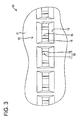
- the retaining wall 11 is formed with one or more, preferably a plurality of retaining holes 12 substantially penetrating from a front surface 11 F of the retaining wall 11 to a rear surface 11 R thereof in forward and backward directions FBD (preferably substantially parallel to a connecting direction CD with a mating connector).
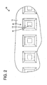
- Each retaining hole 12 is comprised of a front recess 13 making an opening in the front surface 11 F of the retaining wall 11, a rear recess 14 making an opening in the rear surface 11 R of the retaining wall 11, a positioning hole 15 extending substantially backward from the back end surface (rear end) of the front recess 13, and a press-in hole 16 extending substantially in forward and backward directions FBD substantially from the back end surface (rear end) of the positioning hole 15 to the front end surface of the rear recess 14.
- This retaining hole 12 preferably substantially is laterally and/or vertically symmetrical with respect to a line parallel to an inserting direction or press-in direction ID (forward and backward directions FBD) of the tab-shaped terminal 20 into this retaining hole 12.
- a cross-sectional shape of the front recess 13 at an angle different from 0° or 180°, preferably substantially normal to a press-in direction ID of the tab-shaped terminal 20 into the retaining hole 12 (hereinafter, merely "cross-sectional shape”) preferably substantially is square.
- the positioning hole 15 has a mating cross-sectional shape (preferably a substantially square cross-sectional shape) substantially concentric with the front recess 13, but smaller than the front recess 13.
- the rear recess 14 preferably has a different cross-sectional shape (preferably substantially a laterally long rectangular cross-sectional shape) and/or the inner surfaces thereof are so slanted as to widen the rear recess 14 toward the back.
- a minimum vertical dimension (dimension at the front end) of the rear recess 14 preferably is the substantially same as the vertical dimension of the positioning hole 15.
- a minimum lateral dimension (dimension at the front end) of the rear recess 14 preferably is larger than that of the positioning hole 15.
- the press-in hole 16 preferably substantially has a laterally long rectangular cross-sectional shape, the vertical dimension thereof preferably is substantially equal to that of the positioning hole 15, and/or the lateral (upper and/or lower) surface(s) thereof substantially is/are continuous and flush with those of the positioning hole 15.
- a front end portion of the press-in hole 16 serves as a receiving portion 17 whose (preferably substantially opposite) inclined lateral (left and/or right) inner surface(s) is/are inclined to gradually narrow the spacing toward the front.
- An angle ⁇ a formed by the opposite left and right inner surfaces in this receiving portion 17 preferably is an angle close to 90° (e.g. in the range of about 70° to 90°, preferably about 80°).
- the front ends of the opposite left and right inner surfaces of the receiving portion 17 preferably are substantially continuous with and/or at an obtuse angle to the rear ends of the inner side surfaces of the positioning hole 15.
- the opposite lateral (left and/or right) inner surfaces preferably are not parallel to each other, but are so inclined as to gradually widen the spacing from the front end toward the rear end.
- An angle ⁇ b formed by the opposite left and right inner surfaces in this press-in area 18 preferably is smaller than the angle ⁇ a formed by the inner side surfaces of the receiving portion 17 and is in the range of about 1 ° to about 5°, more preferably about 2°.
- the front ends of the opposite inner side surfaces of the press-in area 18 preferably are substantially continuous with and/or at an obtuse angle to the rear ends of the inner side surfaces of the receiving portion 17.
- the rear ends of the opposite inner side surfaces of the press-in area 18 preferably are substantially continuous with and/or at an obtuse angle close to 90° (e.g. in the range of about 70° to 90°, preferably about 80°) to the front surface (back end surface) of the rear recess 14.
- the front surface of the rear recess 14 preferably substantially is a flat surface at an angle different from 0° or 180°, preferably substantially normal to the press-in direction ID (forward and backward directions FBD) of the tab-shaped terminal 20 into the retaining hole 12.
- a width Wa at the rear end of the press-in area 18 i.e. maximum width in the press-in hole 16
- the front surface of the rear recess 14 preferably serves as a stopper 19.
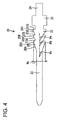
- Each tab-shaped terminal 20 preferably is obtained by punching or stamping or pressing a conductive (preferably metal) plate material into a specified (predetermined or predeterminable) shape and preferably includes a press-in portion 21, a tab-shaped contact portion 22 extending substantially forward from the front end of the press-in portion 21, a front-stop portion 23 extending substantially backward from the rear end of the press-in portion 21 and a connecting portion (preferably a board connecting portion 24) extending backward from the rear end of the front-stop portion 23.
- a conductive (preferably metal) plate material into a specified (predetermined or predeterminable) shape and preferably includes a press-in portion 21, a tab-shaped contact portion 22 extending substantially forward from the front end of the press-in portion 21, a front-stop portion 23 extending substantially backward from the rear end of the press-in portion 21 and a connecting portion (preferably a board connecting portion 24) extending backward from the rear end of the front-stop portion 23.
- the tab-shaped terminal 20 preferably is laterally symmetrical with respect to a line extending in forward and backward directions FBD substantially parallel to the press-in direction ID into the retaining hole 12 and/or vertically symmetrical in a state where the board connecting portion 24 is not bent.
- the press-in portion 21, the tab-shaped contact portion 22 and the front-stop portion 23 preferably have upper and lower surfaces substantially continuous and flush with each other and/or preferably substantially have the same thickness.
- a cross-sectional shape of the tab-shaped contact portion 22 at an angle different from 0° or 180°, preferably substantially normal to the press-in direction preferably is square and/or the vertical dimension (which preferably also is equal to the lateral dimension) thereof preferably is equal to or slightly smaller than that of the positioning hole 15.
- the front-stop portion 23 preferably is rectangular and the front end edge thereof is normal to the press-in direction.
- the board connecting portion 24 has such a known shape as to be bent preferably substantially in L-shape and connected with a circuit board or other electric/electronic device (not shown) while being at least partly inserted through a through hole of the circuit board.
- the vertical dimension of the press-in portion 21 preferably is substantially equal to that of the tab-shaped contact portion 22.
- the lateral dimension of the press-in portion 21 preferably substantially is larger than that of the tab-shaped contact portion 22, and/or substantially smaller than that of the front-stop portion 23.
- One or more, e.g. three (first to third) projections 25A, 25B and 25C are formed on each of the (preferably substantially opposite) lateral (left and/or right) edge(s) of the press-in portion 21 preferably while being spaced apart in the press-in direction ID.
- the projections 25A, 25B and 25C have one or more respective slanted edge portions 26A, 26B and 26C inclined with respect to the press-in direction ID and one or more respective locking edge portions 27A, 27B and 27C preferably substantially normal to the press-in direction, thereby preferably substantially having substantially triangular shapes.
- an angle of inclination ⁇ c of the slanted edge portions 26A of the first projections 25A with respect to the press-in direction ID is smaller than angles of inclination ⁇ d, ⁇ e of the slanted edge portions 26B, 26C of the second and/or third projections 25B, 25C with respect to the press-in direction ID and preferably is in the range of about 5° to about 20°, more preferably is about 10°.
- the angle of inclination ⁇ d of the slanted edge portions 26B of the second projections 25B preferably is substantially equal to the angle of inclination ⁇ e of the slanted edge portions 26C of the third projections 25C.
- Angles of the locking edge portions 27A, 27B and 27C of the respective projections 25A, 25B and 25C with respect to the press-in direction ID preferably are different from each other.
- the locking edge portions 27A of the first projections 25A located at the foremost positions are at an angle of about 90° to the slanted edge portions 26A.
- an angle formed between the locking edge portions 27B and the slanted edge portions 26B is smaller than that of the first projections 25A.
- the third projections 25C located at the rear preferably rearmost position(s)
- an angle formed between the locking edge portions 27C and the slanted edge portions 26C is smallest.
- the angular orientations of the slanted edge portions with respect to the insertion direction ID gradually or stepwisely decrease from the front slanted edge portion toward the back front edge portion (as seen with respect to the insertion direction ID).
- the locking edge portions 27C of the third projections 25C are at an angle closest to a right angle to the press-in direction.
- the angular orientations of the locking edge portions with respect to the insertion direction ID gradually or stepwisely increase from the front slanted edge portion toward the back front edge portion (as seen with respect to the insertion direction ID).
- one or more lines connecting projecting ends of the plurality of e.g. three (pairs of) projections 25A, 25B and 25C along the (preferably substantially opposite) lateral (left and/or right) edge(s) of the press-in portion 21 are so inclined with respect to the inserting direction as to come closer to a longitudinal middle line LML of the press-in portion 21, preferably as to narrow the spacing between the opposite lines toward the front.
- An angle ⁇ f formed or included or defined by a pair of lines connecting the projecting ends of the projections 25A, 25B and 25C preferably is larger than the angle ⁇ b formed by the opposite lateral (left and right) inner surfaces in the press-in area 18 of the press-in hole 16.
- an angle of inclination of the lines connecting the projecting ends of the projections 25A, 25B and 25C with respect to the press-in direction ID preferably substantially is larger than that of the inner side surfaces of the press-in area 18 with respect to the press-in direction ID.
- a front end portion of the press-in portion 21 serves as a biting or engaging portion 28 preferably trapezoidal by having the pair of first projections 25A, and a maximum width Wb of this biting portion 28 (distance between the projecting ends of the first projections 25A) preferably is larger than the maximum width Wa (lateral width at the rear end) of the press-in hole 16.
- An angle 2 ⁇ c formed by the pair of slanted edge portions 26A of this biting portion 28 preferably is smaller than the angle ⁇ a formed by the opposite lateral (left and right) surfaces of the receiving portion 17.
- the front ends of the slanted edge portions 26A of the biting portion 28 preferably are substantially continuous with and/or at an obtuse angle to the lateral edges of the rear end of the tab-shaped contact portion 22.
- the tab-shaped terminal 20 Upon at least partly mounting the tab-shaped terminal 20 into the housing 10, the tab-shaped terminal 20 is at least partly inserted into the retaining hole 12 in the inserting direction ID; preferably substantially from behind, with the tab-shaped contact portion 22 in the lead.
- the tab-shaped contact portion 22 is at least partly fitted into the positioning hole 15 through the press-in hole 16.
- the tab-shaped contact portion 22 Upon being fitted into the positioning hole 15, the tab-shaped contact portion 22 preferably is prevented from making relative movements in the vertical and/or lateral directions.
- the press-in portion 21 When the tab-shaped contact portion 22 starts being at least partly fitted into the positioning hole 15, the press-in portion 21 is located behind the retaining hole 12.
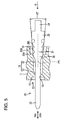
- the slanted edge portions 26A of the (preferably substantially opposite) lateral (left and/or right) first projections 25A of the (preferably substantially trapezoidal) biting portion 28 of the press-in portion 21 come substantially into contact with the opening edge at the rear end of the press-in area 18 with the tab-shaped contact portion 22 at least partly fitted in the positioning hole 15 as shown in FIG. 5 .
- the tab-shaped terminal 20 preferably has the posture thereof corrected in the lateral direction to substantially face or be oriented in the substantially correct press-in direction ID. If a pressing force is applied to the tab-shaped terminal 20 in this state, the press-in portion 21 is pressed into the press-in hole 16.
- the first projection(s) 25A move(s) toward the back side of the press-in hole 16 (move forward) while deforming the (preferably substantially opposite) lateral (left and/or right) inner wall(s) of the press-in area 18 to widen the press-in area 18.
- the second projection(s) 25B at least partly enter the press-in hole 16 and move forward while (preferably further) deforming the inner side surface(s) of the press-in area 18 to widen the press-in area 18.
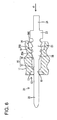
- the third projection(s) 25C are similarly pressed in while deforming the inner side surface(s) of the press-in area 18 to widen the press-in area 18.
- the front-stop portion 23 preferably comes substantially into contact with the stopper 19 (back end surface) of the rear recess 14 as shown in FIG. 7 , whereby any further press-in operation of the tab-shaped terminal 20 is prevented and the projections 25A, 25B and 25C bite in the inner walls of the press-in hole 16 to preferably prevent a returning movement of the tab-shaped terminal 20. Further, the front end of the biting portion 28 bites in the inner side surfaces of the front end portion of the receiving portion 17 and the opening edge at the rear end of the positioning hole 15.
- the press-in hole 16 preferably is so tapered as to be gradually wider from the front end toward the rear end in this embodiment, a large dimensional difference between the width of the press-in hole 16 and that of the press-in portion 21 can be ensured at the front end portion of the press-in hole 16, so that that the tab-shaped terminal 20 can be reliably retained in the housing 10.
- the dimensional difference between the width of the press-in hole 16 and that of the press-in portion 21 is small at the rear end portion of the press-in hole 16, press-in resistance at an initial stage of the press-in process can be reduced.
- the tab-shaped contact portion 22 preferably is positioned in the width direction by the positioning hole 15, the tab-shaped terminal 20 can be mounted at a correct position in the housing 10.
- the front end portion of the press-in portion 21 preferably serves as the biting portion 28 having such a (preferably substantially trapezoidal or widened or diverging) shape as to be wider toward the back, and the maximum width Wa at the rear end of the press-in hole 16 preferably is smaller than the width Wb of the (trapezoidal or widened or diverging) biting portion 28.
- the slanted edge portions 26A of the trapezoidal biting portion 28 preferably come substantially into contact with the opening edge of the press-in hole 16 at the start of the press-in process, whereby press-in resistance is reduced by the inclination of the slanted edge portions 26A.
- the front end portion of the press-in portion 21 preferably serves as the biting portion 28 whose opposite lateral (left and/or right) edges are inclined to narrow the spacing toward the front
- the front end portion of the press-in hole 16 serves as the receiving portion 17 whose lateral (left and/or right) inner surface(s) are inclined with respect to the inserting direction ID preferably to narrow the spacing toward the front
- the angle formed by the (preferably substantially opposite) lateral (left and/or right) edge(s) (slanted edge portion(s) 26A) of the biting portion 28 preferably is smaller than the angle formed by the (preferably substantially opposite) lateral (left and/or right) inner surface(s) of the receiving portion 17.
- the biting portion 28 bites in or engages the receiving portion 17 after the press-in process is completed, wherefore the tab-shaped terminal 20 is more reliably retained by this biting action.
- the plurality of pointed projections 25A, 25B and 25C (e.g. the three pairs of substantially triangular projections 25A, 25B and 25C) spaced apart in the press-in direction ID are formed on the one or both lateral edges (preferably on substantially opposite left and right edges) of the press-in portion 21 and these projections 25A, 25B and 25C bite in or engage the inner side surface(s) of the press-in hole 16, wherefore the pressed-in tab-shaped terminal 20 is reliably retained.
- the lines connecting the projecting ends of the projections 25A, 25B and 25C of the three pairs of projections 25A, 25B and 25C along the (preferably substantially opposite) lateral (left and/or right) edge(s) of the press-in portion 21 are inclined with respect to the inserting direction ID, to preferably narrow the spacing therebetween toward the front, and/or the press-in portion 21 including these projections 25A, 25B and 25C is tapered toward the front end as a whole. Therefore, press-in resistance at the initial stage of the press-in process is reduced.
- a press-in hole 16 of a housing 10 is formed to be gradually wider from the front end toward the rear end, a large dimensional difference between the width of the press-in hole 16 and that of a press-in portion 21 of a tab-shaped terminal 20 is ensured at a front end portion of the press-in hole 16, so that the tab-shaped terminal 20 can be reliably retained in the housing 10.
- the dimensional difference between the width of the press-in hole 16 and that of the press-in portion 21 is small at a rear end portion of the press-in hole 16, press-in resistance at an initial stage of a press-in process is reduced.
Landscapes
- Connector Housings Or Holding Contact Members (AREA)
Claims (15)
- Un connecteur, comprenant:un boîtier (10) composé de résine synthétique et constitué avec au moins un trou à enfoncement (press-in) (16) s'étendant essentiellement dans des directions avant et arrière (FBD), etau moins un bornier (20) incluant une portion de contact (22) dans une portion d'extrémité frontale et une portion d'enfoncement (21) plus ample que le trou à enfoncement (16) et présentant une continuité avec l'extrémité arrière de la portion de contact (22), le bornier (20) étant retenu dans le boîtier (10) en enfonçant la portion d'enfoncement (21) dans le trou à enfoncement (16) dans une direction d'enfoncement (ID),caractérisé en ce quele trou à enfoncement (16) est constitué pour être de plus en plus ample à partir de l'extrémité frontale de celui-ci vers l'extrémité arrière de celui-ci,une portion d'extrémité frontale du trou à enfoncement (16) sert de portion de réception (17), dont une ou plusieurs surfaces latérales sont inclinées par rapport à la direction d'enfoncement (ID), etdans une zone d'enfoncement (18) du trou à enfoncement (16) derrière la portion de réception (17) les surfaces intérieures latérales opposées sont inclinées de telle manière qu'elles élargissent de plus en plus l'écartement à partir de l'extrémité frontale vers l'extrémité arrière, sachant que l'angle (θb), défini par les surfaces intérieures latérales opposées dans cette zone d'enfoncement (18) est plus petit que l'angle (θa) formé par les surfaces du côté intérieur de la portion de réception (17).
- Un connecteur d'après la revendication 1, sachant qu'un trou de positionnement (15), capable de positionner la portion de contact (22) dans une direction de largeur en faisant ainsi que la portion de contact (22) soit mise en place dans celui-ci, est constitué pour présenter essentiellement une continuité avec l'extrémité frontale du trou d'enfoncement (16) dans le boîtier (10).
- Un connecteur d'après une des revendications précédentes, sachant qu'une portion d'extrémité frontale (28) de la portion d'enfoncement (21) est constituée pour présenter une forme trapézoïdale de manière à être plus ample vers l'arrière.
- Un connecteur d'après la revendication 3, sachant qu'une ampleur maximale (Wa) de l'extrémité arrière du trou à enfoncement (16) est inférieure à l'ampleur (Wb) de la portion d'extrémité frontale (28) trapézoïdale.
- Un connecteur d'après une des revendications précédentes, sachant que :une portion d'extrémité frontale (28) de la portion d'enfoncement (21) sert de portion mordante (28), dont le ou les bords latéraux sont inclinés par rapport à la direction d'enfoncement (ID), et préférablement dont les bords latéraux opposés sont inclinés pour réduire l'écartement vers l'avant.
- Un connecteur d'après une des revendications précédentes, sachant que les surfaces intérieures latérales opposées de la portion de réception (17) sont inclinées pour réduire l'écartement vers l'avant.
- Un connecteur d'après la revendication 5 ou 6, sachant qu'un angle constitué par les bords latéraux opposés de la portion mordante (28) est inférieur à un angle constitué par les surfaces intérieures latérales opposées de la portion de réception (17).
- Un connecteur d'après une des revendications précédentes, sachant qu'une pluralité de saillies essentiellement triangulaires (25A, 25B, 25C) sont formées sur un ou plusieurs bords latéraux de la portion d'enfoncement (21) tout en étant écartées dans une direction d'enfoncement (ID).
- Un connecteur d'après la revendication 8, sachant que la pluralité de saillies (25A, 25B, 25C) sont constituées de manière que des lignes raccordant les extrémités saillantes de la pluralité de saillies (25A, 25B, 25C) le long des bords latéraux opposés de la portion d'enfoncement (21) sont inclinées pour réduire l'écartement vers l'avant.
- Un connecteur d'après la revendication 9, sachant qu'un angle (θf) défini par une paire de lignes raccordant les extrémités saillantes des saillies (25A, 25B, 25C) est plus grand que l'angle (θb) défini par les surfaces intérieures latérales opposées du trou à enfoncement (16).
- Un connecteur d'après une des revendications précédentes de 8 à 10, sachant qu'un angle d'inclinaison (θc) des portions de bord oblique (26A) d'une première saillie (25A) par rapport à la direction d'enfoncement (ID) est plus petit qu'un ou plusieurs angles d'inclinaison (θd, θe) de la ou des portions de bord oblique (26B, 26C) de l'autre ou des autres saillies (25B, 25C) par rapport à la direction d'enfoncement (ID) et se situe préférablement dans l'intervalle compris entre à peu près 5° et à peu près 20°, et comporte notamment à peu près 10°.
- Un connecteur d'après une des revendications précédentes, sachant que l'angle (θb) défini par les surfaces intérieures latérales opposées de la zone d'enfoncement (18) se situe dans l'intervalle compris entre à peu près 1° et à peu près 5°, et comporte préférablement à peu près 2°.
- Un connecteur d'après une des revendications précédentes, sachant que des extrémités frontales des surfaces intérieures opposées de la zone d'enfoncement (18) présentent essentiellement une continuité et/ou un angle obtus avec les extrémités arrières des surfaces intérieures de la portion de réception (17), sachant que les extrémités arrières des surfaces intérieures opposées de la zone d'enfoncement (18) présentent de préférence essentiellement une continuité et/ou an angle obtus situé dans l'intervalle compris entre à peu près 70° et à peu près 90°, et comportant notamment à peu près 80°, avec la surface frontale d'un renfoncement arrière (14) du boîtier (10) agencé derrière le trou à enfoncement (16).
- Un connecteur d'après une des revendications précédentes, sachant que le boîtier (10) comprend au moins un renfoncement arrière (14) agencé derrière le trou à enfoncement (16), sachant qu'une surface frontale du renfoncement arrière (14) est essentiellement une surface plate présentant un angle autre que 0° ou 180°, de préférence essentiellement normal par rapport à la direction d'enfoncement (ID), sachant qu'une ampleur (Wa) du trou à enfoncement (16), préférablement une ampleur maximale du trou à enfoncement (16), est préférablement plus petite que l'ampleur minimale du renfoncement arrière (14).
- Un connecteur d'après une des revendications précédentes, sachant que le bornier (20) inclut une portion de butée avant (20) qui entre en contact avec une portion (19) du boîtier (10), quand le bornier (20) atteint une position d'enfoncement essentiellement correcte, par conséquent toute opération d'enfoncement supplémentaire du bornier (20) est évitée.
Applications Claiming Priority (1)
| Application Number | Priority Date | Filing Date | Title |
|---|---|---|---|
| JP2007286011A JP5115149B2 (ja) | 2007-11-02 | 2007-11-02 | コネクタ |
Publications (3)
| Publication Number | Publication Date |
|---|---|
| EP2056410A2 EP2056410A2 (fr) | 2009-05-06 |
| EP2056410A3 EP2056410A3 (fr) | 2010-02-17 |
| EP2056410B1 true EP2056410B1 (fr) | 2014-09-17 |
Family
ID=40260575
Family Applications (1)
| Application Number | Title | Priority Date | Filing Date |
|---|---|---|---|
| EP08018752.9A Ceased EP2056410B1 (fr) | 2007-11-02 | 2008-10-27 | Un connecteur électrique |
Country Status (5)
| Country | Link |
|---|---|
| US (1) | US7722413B2 (fr) |
| EP (1) | EP2056410B1 (fr) |
| JP (1) | JP5115149B2 (fr) |
| KR (1) | KR101038036B1 (fr) |
| CN (1) | CN101425639B (fr) |
Families Citing this family (44)
| Publication number | Priority date | Publication date | Assignee | Title |
|---|---|---|---|---|
| CN101652902B (zh) * | 2007-02-02 | 2013-02-13 | 富加宜汽车控股公司 | 连接设备 |
| JP2009151939A (ja) * | 2007-12-18 | 2009-07-09 | Tyco Electronics Amp Kk | 端子圧入構造および電気コネクタ |
| US8083554B2 (en) * | 2009-06-05 | 2011-12-27 | Tyco Electronics Corporation | Connector assembly having a unitary housing |
| DE102009025113A1 (de) * | 2009-06-11 | 2010-12-16 | Continental Teves Ag & Co. Ohg | Einpresskontakt zur Verbindung eines elektronischen Bauelementes mit einer Leiterplatte sowie Einpresswerkzeug |
| KR101101246B1 (ko) * | 2009-09-02 | 2012-01-04 | 김정안 | 조립이 쉽고 접촉이 안정적인 프로브 카드용 연결기 |
| US8123569B2 (en) * | 2010-02-08 | 2012-02-28 | Hon Hai Precision Ind. Co., Ltd. | Waterproof audio jack connector |
| JP5623812B2 (ja) * | 2010-07-14 | 2014-11-12 | 日本航空電子工業株式会社 | コネクタ |
| JP5494381B2 (ja) * | 2010-09-14 | 2014-05-14 | 住友電装株式会社 | コネクタ |
| JP5736262B2 (ja) * | 2011-07-14 | 2015-06-17 | モレックス インコーポレイテドMolex Incorporated | 多接点コネクタ |
| JP2013037791A (ja) * | 2011-08-04 | 2013-02-21 | Sumitomo Wiring Syst Ltd | 回路基板と端子金具の接続構造 |
| JP5795907B2 (ja) * | 2011-08-29 | 2015-10-14 | 矢崎総業株式会社 | 基板コネクタ用の圧入端子およびその圧入端子のコネクタハウジングに対する固定構造 |
| US8506336B2 (en) | 2011-09-02 | 2013-08-13 | Tyco Electronics Corporation | Stamped and formed contact |
| JP5392329B2 (ja) * | 2011-09-13 | 2014-01-22 | 第一精工株式会社 | 圧入端子 |
| JP5729648B2 (ja) * | 2011-10-13 | 2015-06-03 | ホシデン株式会社 | 太陽電池モジュール用端子ボックス |
| JP2013131364A (ja) * | 2011-12-21 | 2013-07-04 | Sumitomo Wiring Syst Ltd | 端子金具及び端子金具の接続構造 |
| DE102012104680A1 (de) * | 2012-05-30 | 2013-12-05 | Tyco Electronics Amp Gmbh | Elektrisches Steckerelement mit selbstabdichtender Kontaktaufnahme und Kontaktelement hierfür |
| JP6068061B2 (ja) * | 2012-08-31 | 2017-01-25 | 矢崎総業株式会社 | 端子圧入構造 |
| DE102013215302A1 (de) * | 2013-08-02 | 2015-02-05 | Tyco Electronics Belgium Ec Bvba | Flachkontakt für einen Stecker, Aufnahmeblock für einen Flachkontakt und Stecker |
| US20150173181A1 (en) * | 2013-12-16 | 2015-06-18 | Cisco Technology, Inc. | Enlarged Press-Fit Hole |
| EP2887462B1 (fr) * | 2013-12-20 | 2021-03-03 | Pierburg Pump Technology GmbH | Agrégat auxiliaire électrique d'un véhicule |
| TWI569521B (zh) * | 2014-05-23 | 2017-02-01 | 鴻騰精密科技股份有限公司 | 卡緣連接器 |
| JP6227484B2 (ja) * | 2014-05-30 | 2017-11-08 | 日本航空電子工業株式会社 | コネクタ |
| JP2016018595A (ja) * | 2014-07-04 | 2016-02-01 | タイコエレクトロニクスジャパン合同会社 | 電気コネクタ |
| JP6427348B2 (ja) * | 2014-07-16 | 2018-11-21 | 矢崎総業株式会社 | コネクタ |
| JP2016024857A (ja) * | 2014-07-16 | 2016-02-08 | 矢崎総業株式会社 | コネクタ |
| TWM518835U (zh) * | 2014-11-17 | 2016-03-11 | 宣德科技股份有限公司 | 電子連接器結構 |
| DE102015205964A1 (de) * | 2015-02-17 | 2016-08-18 | Te Connectivity Germany Gmbh | Abgewinkelter Kontaktstift zum Einpressen in eine Kontaktstiftaufnahme, Steckverbinder mit wenigstens einem Kontaktstift und Verfahren zur Herstellung eines Steckverbinders |
| JP6209551B2 (ja) * | 2015-03-30 | 2017-10-04 | 矢崎総業株式会社 | コネクタ及びその製造方法 |
| EP3278401B1 (fr) | 2015-04-01 | 2021-11-03 | TE Connectivity Germany GmbH | Broche de contact coudée destinée à être poussée dans une prise de broche de contact, connecteur pourvu d'au moins une broche de contact, et procédé de fabrication d'un connecteur |
| JP6550890B2 (ja) * | 2015-04-22 | 2019-07-31 | 住友電装株式会社 | プレスフィット端子 |
| CN107645096A (zh) * | 2016-07-22 | 2018-01-30 | 东莞莫仕连接器有限公司 | 电连接器 |
| JP2018037505A (ja) * | 2016-08-31 | 2018-03-08 | 住友電装株式会社 | 基板端子付プリント基板 |
| CN110366876B (zh) * | 2017-03-06 | 2023-05-05 | 三菱电机株式会社 | 具有压配结构的控制单元 |
| DE102017111293A1 (de) * | 2017-05-23 | 2018-11-29 | Te Connectivity Germany Gmbh | Kontaktstift |
| CN108448281A (zh) * | 2018-03-21 | 2018-08-24 | 菲尼克斯亚太电气(南京)有限公司 | 一种连接器用两体式插针 |
| DE102018113980A1 (de) | 2018-06-12 | 2019-12-12 | Te Connectivity Germany Gmbh | Verfahren zur Herstellung eines elektrischen Verbinders, insbesondere elektrischer Verbinder für ein hochdichtes Header System; sowie elektrischer Verbinder, insbesondere elektrischer Verbinder für den Kraftfahrzeugbereich; und ein Hochdichtes Header System |
| CN109546395B (zh) * | 2018-11-09 | 2021-01-22 | 贵州振华华联电子有限公司 | 一种异型结构的汽车接插件 |
| GB201902220D0 (en) * | 2019-02-18 | 2019-04-03 | Nicoventures Trading Ltd | Aerosol provision systems |
| JP7272011B2 (ja) * | 2019-02-27 | 2023-05-12 | 住友電装株式会社 | 基板用コネクタ |
| JP7352184B2 (ja) * | 2020-02-20 | 2023-09-28 | 住友電装株式会社 | コネクタ |
| CN111969376B (zh) * | 2020-07-06 | 2022-02-11 | 中航光电科技股份有限公司 | 一种兼容vpx标准的lrm光电射频集成连接器 |
| JP7727896B2 (ja) * | 2021-12-28 | 2025-08-22 | 住友電装株式会社 | 端子金具及びコネクタ |
| US20250192460A1 (en) * | 2023-12-08 | 2025-06-12 | Arista Networks, Inc. | Port Cage Retention |
| JP2025159457A (ja) * | 2024-04-08 | 2025-10-21 | 住友電装株式会社 | コネクタ |
Family Cites Families (20)
| Publication number | Priority date | Publication date | Assignee | Title |
|---|---|---|---|---|
| US3530422A (en) * | 1968-03-25 | 1970-09-22 | Elco Corp | Connector and method for attaching same to printed circuit board |
| GB8908411D0 (en) * | 1989-04-13 | 1989-06-01 | Amp Holland | Surface mount electrical connector |
| JP2580865Y2 (ja) * | 1993-04-09 | 1998-09-17 | 日本エー・エム・ピー株式会社 | コネクタ |
| US5460549A (en) * | 1994-09-02 | 1995-10-24 | Itt Industries, Inc. | Connector with sealed contacts |
| DE19614706C2 (de) * | 1996-04-13 | 1998-02-26 | Telefunken Microelectron | Verfahren zur Herstellung von elektrisch leitenden Durchführungen in metallisierten Kunststoffgehäusen |
| US6042389A (en) * | 1996-10-10 | 2000-03-28 | Berg Technology, Inc. | Low profile connector |
| KR200232341Y1 (ko) | 1998-05-13 | 2001-08-07 | 이형도 | 파워 모듈 패키지용 터미널 프레임 구조 |
| JP2002129337A (ja) * | 2000-10-24 | 2002-05-09 | Applied Materials Inc | 気相堆積方法及び装置 |
| KR20040020773A (ko) * | 2002-09-03 | 2004-03-09 | 최명부 | 음이온 은(銀)항균 안경테 제조 |
| KR20040042919A (ko) * | 2002-11-14 | 2004-05-22 | 삼성전자주식회사 | 와이어 본더 및 그에 의한 와이어 본딩 방법 |
| JP2004362814A (ja) * | 2003-06-02 | 2004-12-24 | Sumitomo Wiring Syst Ltd | コネクタ及び端子金具 |
| JP2005135794A (ja) * | 2003-10-31 | 2005-05-26 | Hirose Electric Co Ltd | 圧入端子のモールド圧入構造とこのモールド圧入構造を用いた電気コネクタ |
| JP4179170B2 (ja) * | 2004-01-16 | 2008-11-12 | 住友電装株式会社 | コネクタ |
| JP4259405B2 (ja) * | 2004-06-15 | 2009-04-30 | 住友電装株式会社 | 基板用コネクタ |
| JP2006019228A (ja) | 2004-07-05 | 2006-01-19 | Sumitomo Wiring Syst Ltd | 基板用コネクタ |
| JP4320296B2 (ja) * | 2004-11-18 | 2009-08-26 | ケル株式会社 | 電線圧接型コネクタ |
| CN2791929Y (zh) * | 2005-04-30 | 2006-06-28 | 陈文雄 | 连接器 |
| KR200420773Y1 (ko) | 2006-04-27 | 2006-07-05 | 경신공업 주식회사 | 방수커넥터용 공용화 방수씰 |
| JP2007311092A (ja) * | 2006-05-17 | 2007-11-29 | Yazaki Corp | 印刷配線板組立体及び該印刷配線板組立体の製造方法 |
| KR200442919Y1 (ko) | 2007-04-24 | 2008-12-22 | 한국단자공업 주식회사 | 커넥터 |
-
2007
- 2007-11-02 JP JP2007286011A patent/JP5115149B2/ja not_active Expired - Fee Related
-
2008
- 2008-10-27 EP EP08018752.9A patent/EP2056410B1/fr not_active Ceased
- 2008-10-31 US US12/262,347 patent/US7722413B2/en active Active
- 2008-10-31 KR KR1020080107586A patent/KR101038036B1/ko not_active Expired - Fee Related
- 2008-11-03 CN CN2008101704196A patent/CN101425639B/zh not_active Expired - Fee Related
Also Published As
| Publication number | Publication date |
|---|---|
| KR20090045867A (ko) | 2009-05-08 |
| JP5115149B2 (ja) | 2013-01-09 |
| US20090117755A1 (en) | 2009-05-07 |
| JP2009117064A (ja) | 2009-05-28 |
| EP2056410A3 (fr) | 2010-02-17 |
| EP2056410A2 (fr) | 2009-05-06 |
| KR101038036B1 (ko) | 2011-05-31 |
| CN101425639B (zh) | 2011-07-06 |
| CN101425639A (zh) | 2009-05-06 |
| US7722413B2 (en) | 2010-05-25 |
Similar Documents
| Publication | Publication Date | Title |
|---|---|---|
| EP2056410B1 (fr) | Un connecteur électrique | |
| US7708605B2 (en) | Connector with terminal fittings press fit in a base wall of a connector housing | |
| CN101997229B (zh) | 连接器和电子设备 | |
| US10135196B2 (en) | Electrical connector having improved conductive terminals | |
| CN101752713B (zh) | 电连接器 | |
| US7883362B2 (en) | Joint connector, joint terminal and a wiring harness with a joint connector | |
| TWI408853B (zh) | 基板對基板連接器 | |
| EP1608041A2 (fr) | Connecteur électrique et méthode d'assemblage | |
| US8070515B2 (en) | Shield case with u-shaped base with a first plate and second plates and side walls parallel to second plates | |
| US8348707B2 (en) | Terminal fitting | |
| US20080153359A1 (en) | Electrical connector | |
| US7520785B2 (en) | Connector | |
| US20020081885A1 (en) | Card edge connector | |
| US7985080B2 (en) | Electrical connector having auxiliary hold-down arrangement | |
| JP4385923B2 (ja) | 端子金具及びこれを用いたコネクタ | |
| US10559900B2 (en) | Board connector with tool installation space for beding a terminal fitting | |
| US8454380B2 (en) | Card edge connector | |
| CN111033903A (zh) | 端子配件 | |
| US7001214B2 (en) | Connector | |
| JP2021057184A (ja) | 雄端子、および雄コネクタ | |
| US11264751B2 (en) | Male connector provided with housing that accomodates male terminal | |
| US7963798B1 (en) | Electrical connector with locking member for mounting thereof to printed circuit board | |
| US20080124949A1 (en) | Contact terminal for electrical connector | |
| JP3124421U (ja) | 基板実装された電気コネクタ | |
| CN121219917A (zh) | 连接器 |
Legal Events
| Date | Code | Title | Description |
|---|---|---|---|
| PUAI | Public reference made under article 153(3) epc to a published international application that has entered the european phase |
Free format text: ORIGINAL CODE: 0009012 |
|
| 17P | Request for examination filed |
Effective date: 20081106 |
|
| AK | Designated contracting states |
Kind code of ref document: A2 Designated state(s): AT BE BG CH CY CZ DE DK EE ES FI FR GB GR HR HU IE IS IT LI LT LU LV MC MT NL NO PL PT RO SE SI SK TR |
|
| AX | Request for extension of the european patent |
Extension state: AL BA MK RS |
|
| PUAL | Search report despatched |
Free format text: ORIGINAL CODE: 0009013 |
|
| AK | Designated contracting states |
Kind code of ref document: A3 Designated state(s): AT BE BG CH CY CZ DE DK EE ES FI FR GB GR HR HU IE IS IT LI LT LU LV MC MT NL NO PL PT RO SE SI SK TR |
|
| AX | Request for extension of the european patent |
Extension state: AL BA MK RS |
|
| 17Q | First examination report despatched |
Effective date: 20100521 |
|
| AKX | Designation fees paid |
Designated state(s): DE FR IT |
|
| GRAP | Despatch of communication of intention to grant a patent |
Free format text: ORIGINAL CODE: EPIDOSNIGR1 |
|
| INTG | Intention to grant announced |
Effective date: 20140124 |
|
| RIN1 | Information on inventor provided before grant (corrected) |
Inventor name: SONOSAKI, TAKASHI |
|
| RIN1 | Information on inventor provided before grant (corrected) |
Inventor name: TONOSAKI, TAKASHI |
|
| GRAP | Despatch of communication of intention to grant a patent |
Free format text: ORIGINAL CODE: EPIDOSNIGR1 |
|
| INTG | Intention to grant announced |
Effective date: 20140616 |
|
| GRAS | Grant fee paid |
Free format text: ORIGINAL CODE: EPIDOSNIGR3 |
|
| GRAA | (expected) grant |
Free format text: ORIGINAL CODE: 0009210 |
|
| AK | Designated contracting states |
Kind code of ref document: B1 Designated state(s): DE FR IT |
|
| RIN1 | Information on inventor provided before grant (corrected) |
Inventor name: TONOSAKI, TAKASHI |
|
| REG | Reference to a national code |
Ref country code: DE Ref legal event code: R096 Ref document number: 602008034414 Country of ref document: DE Effective date: 20141023 |
|
| REG | Reference to a national code |
Ref country code: DE Ref legal event code: R097 Ref document number: 602008034414 Country of ref document: DE |
|
| PLBE | No opposition filed within time limit |
Free format text: ORIGINAL CODE: 0009261 |
|
| STAA | Information on the status of an ep patent application or granted ep patent |
Free format text: STATUS: NO OPPOSITION FILED WITHIN TIME LIMIT |
|
| 26N | No opposition filed |
Effective date: 20150618 |
|
| REG | Reference to a national code |
Ref country code: FR Ref legal event code: PLFP Year of fee payment: 9 |
|
| REG | Reference to a national code |
Ref country code: FR Ref legal event code: PLFP Year of fee payment: 10 |
|
| REG | Reference to a national code |
Ref country code: DE Ref legal event code: R084 Ref document number: 602008034414 Country of ref document: DE |
|
| REG | Reference to a national code |
Ref country code: FR Ref legal event code: PLFP Year of fee payment: 11 |
|
| PGFP | Annual fee paid to national office [announced via postgrant information from national office to epo] |
Ref country code: FR Payment date: 20200914 Year of fee payment: 13 |
|
| PGFP | Annual fee paid to national office [announced via postgrant information from national office to epo] |
Ref country code: IT Payment date: 20200911 Year of fee payment: 13 |
|
| PG25 | Lapsed in a contracting state [announced via postgrant information from national office to epo] |
Ref country code: FR Free format text: LAPSE BECAUSE OF NON-PAYMENT OF DUE FEES Effective date: 20211031 |
|
| PG25 | Lapsed in a contracting state [announced via postgrant information from national office to epo] |
Ref country code: IT Free format text: LAPSE BECAUSE OF NON-PAYMENT OF DUE FEES Effective date: 20211027 |
|
| P01 | Opt-out of the competence of the unified patent court (upc) registered |
Effective date: 20230517 |
|
| PGFP | Annual fee paid to national office [announced via postgrant information from national office to epo] |
Ref country code: DE Payment date: 20230830 Year of fee payment: 16 |
|
| REG | Reference to a national code |
Ref country code: DE Ref legal event code: R119 Ref document number: 602008034414 Country of ref document: DE |
|
| PG25 | Lapsed in a contracting state [announced via postgrant information from national office to epo] |
Ref country code: DE Free format text: LAPSE BECAUSE OF NON-PAYMENT OF DUE FEES Effective date: 20250501 |