EP2058061A1 - Outil de formage pour pliage angulaire negatif - Google Patents
Outil de formage pour pliage angulaire negatif Download PDFInfo
- Publication number
- EP2058061A1 EP2058061A1 EP08011615A EP08011615A EP2058061A1 EP 2058061 A1 EP2058061 A1 EP 2058061A1 EP 08011615 A EP08011615 A EP 08011615A EP 08011615 A EP08011615 A EP 08011615A EP 2058061 A1 EP2058061 A1 EP 2058061A1
- Authority
- EP
- European Patent Office
- Prior art keywords
- cam
- slide
- die
- negative
- rotary cam
- Prior art date
- Legal status (The legal status is an assumption and is not a legal conclusion. Google has not performed a legal analysis and makes no representation as to the accuracy of the status listed.)
- Granted
Links
- 238000005452 bending Methods 0.000 claims abstract description 46
- 239000002994 raw material Substances 0.000 description 3
- 238000000926 separation method Methods 0.000 description 3
Images





Classifications
-
- B—PERFORMING OPERATIONS; TRANSPORTING
- B21—MECHANICAL METAL-WORKING WITHOUT ESSENTIALLY REMOVING MATERIAL; PUNCHING METAL
- B21D—WORKING OR PROCESSING OF SHEET METAL OR METAL TUBES, RODS OR PROFILES WITHOUT ESSENTIALLY REMOVING MATERIAL; PUNCHING METAL
- B21D5/00—Bending sheet metal along straight lines, e.g. to form simple curves
- B21D5/04—Bending sheet metal along straight lines, e.g. to form simple curves on brakes making use of clamping means on one side of the work
-
- B—PERFORMING OPERATIONS; TRANSPORTING
- B21—MECHANICAL METAL-WORKING WITHOUT ESSENTIALLY REMOVING MATERIAL; PUNCHING METAL
- B21D—WORKING OR PROCESSING OF SHEET METAL OR METAL TUBES, RODS OR PROFILES WITHOUT ESSENTIALLY REMOVING MATERIAL; PUNCHING METAL
- B21D22/00—Shaping without cutting, by stamping, spinning, or deep-drawing
- B21D22/02—Stamping using rigid devices or tools
- B21D22/04—Stamping using rigid devices or tools for dimpling
-
- B—PERFORMING OPERATIONS; TRANSPORTING
- B21—MECHANICAL METAL-WORKING WITHOUT ESSENTIALLY REMOVING MATERIAL; PUNCHING METAL
- B21D—WORKING OR PROCESSING OF SHEET METAL OR METAL TUBES, RODS OR PROFILES WITHOUT ESSENTIALLY REMOVING MATERIAL; PUNCHING METAL
- B21D19/00—Flanging or other edge treatment, e.g. of tubes
- B21D19/08—Flanging or other edge treatment, e.g. of tubes by single or successive action of pressing tools, e.g. vice jaws
- B21D19/082—Flanging or other edge treatment, e.g. of tubes by single or successive action of pressing tools, e.g. vice jaws for making negative angles
- B21D19/084—Flanging or other edge treatment, e.g. of tubes by single or successive action of pressing tools, e.g. vice jaws for making negative angles with linear cams, e.g. aerial cams
-
- B—PERFORMING OPERATIONS; TRANSPORTING
- B21—MECHANICAL METAL-WORKING WITHOUT ESSENTIALLY REMOVING MATERIAL; PUNCHING METAL
- B21D—WORKING OR PROCESSING OF SHEET METAL OR METAL TUBES, RODS OR PROFILES WITHOUT ESSENTIALLY REMOVING MATERIAL; PUNCHING METAL
- B21D22/00—Shaping without cutting, by stamping, spinning, or deep-drawing
-
- B—PERFORMING OPERATIONS; TRANSPORTING
- B21—MECHANICAL METAL-WORKING WITHOUT ESSENTIALLY REMOVING MATERIAL; PUNCHING METAL
- B21D—WORKING OR PROCESSING OF SHEET METAL OR METAL TUBES, RODS OR PROFILES WITHOUT ESSENTIALLY REMOVING MATERIAL; PUNCHING METAL
- B21D22/00—Shaping without cutting, by stamping, spinning, or deep-drawing
- B21D22/02—Stamping using rigid devices or tools
- B21D22/08—Stamping using rigid devices or tools with die parts on rotating carriers
-
- B—PERFORMING OPERATIONS; TRANSPORTING
- B21—MECHANICAL METAL-WORKING WITHOUT ESSENTIALLY REMOVING MATERIAL; PUNCHING METAL
- B21D—WORKING OR PROCESSING OF SHEET METAL OR METAL TUBES, RODS OR PROFILES WITHOUT ESSENTIALLY REMOVING MATERIAL; PUNCHING METAL
- B21D37/00—Tools as parts of machines covered by this subclass
- B21D37/08—Dies with different parts for several steps in a process
Definitions
- the present invention relates to a negative-angle press-working die, which performs bending or the like of an automobile panel with negative angle working.
- Negative angle working to be performed on a front pillar, roof and rear window of a body side outer panel of an automobile panel is difficult as the front pillar, roof and rear window have complicated cross-sectional shapes. Because the cross-sectional shape of a portion from the front pillar to the roof needs to keep the strength with a small cross section, negative angle forming of this part is particularly difficult.
- a press-working die to overcome such difficulty a press-working die disclosed in, for example, JP-A-59-197318 is known. As shown in Fig.
- the press-working die is of a columnar cam type that includes a lower die having a hold part 16b for holding a raw material on the upper portion of a fixed punch 16a of the lower die, and a cam groove having an arc surface continual to the hold part 16b, a columnar rotary cam 17 which is provided at the lower die 14 to be rotatably inserted in the cam groove and has a bending part 17a at its one end, an elevatable and laterally slidable aerial cam which is provided above the rotary cam 17, has a bending blade at a distal end, and rotates the rotary cam 17 in a direction of holding the raw material, and a pad elevatably disposed above the hold part 16b of the lower die.
- the press-working die performs complicated bending of the pillar (workpiece 12) with the rotary cam 17.
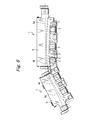
- the demanded cross-sectional shape of a workpiece is getting complicated, for example, from the one shown in Fig. 8A to the one shown in Fig. 8B , so that even the use of the conventional negative-angle press-working die makes it difficult to achieve negative angle forming. That is, as shown in Fig. 8B , the shape is thin and has deep bending, so that the width where the fixed punch 16a or hold part is present cannot be set, and with a clearance 18 for panel removal provided, the space becomes larger, so that the raw material panel cannot be pressed with the pad of the upper die. This leads to reduction in the quality of the formed panel.
- a negative-angle press-working die including an elevatable pad fixed to an upper die; a slide cam supported on the upper die or a lower die, forming a bending blade at one end portion, having cam surfaces on both upper and lower sides, and supported so as to laterally slide along the both cam surfaces; a rotary cam having, at one end thereof, a bending part which forms a negative-angle portion on a workpiece, having a cam surface abutting on one of the cam surfaces of the slide cam, and being rotatable about a rotational center; a slide body disposed under the pad, having a hold part provided at an upper portion on a bending part side of the rotary cam and constituting a part of a male die for workpiece forming, being elevatably held, and rotatable together with the rotary cam; a drive unit that rotates the rotary cam at a workpiece working position; and a slide drive unit that slides the slide body in an up and down direction.
- the drive unit should be disposed under the rotary cam, and have a horizontally movable slide block provided at a drive-axial distal end of an air cylinder and having a tapered portion at an upper surface on a distal end side, and the rotary cam should be rotated as the tapered portion abuts on a lower portion of the rotary cam to push up the lower portion.
- the slide drive unit preferably includes a cam slide having, on an upper side, a cam surface on which the slide body is slidable, and having a lower end supported at an end portion of the rotary cam so as to be movable laterally, an urging section that urges the cam slide in a direction away from the rotational center of the rotary cam, and an upper die driver having, at a lower end portion of a side face thereof, a cam surface which abuts on an upper end portion of a side face of the cam slide to forcibly move the cam slide laterally, and fixed to the upper die.
- the negative-angle press-working die according to the present invention not only can form a negative angle with deep bending, which cannot be achieved by a columnar cam type using the rotary cam of the prior art, but also need not form a panel removing clearance needed by the prior art to remove a panel, thereby improving the quality of the panel dramatically.
- the present invention particularly and preferably provides to enable forming a negative angle with deep bending and forming a high-quality panel, a negative-angle press-working die (1) including an elevatable pad (3) fixed to an upper die (2), a slide cam (4) supported slidable laterally on the upper die (2) or a lower die (14) and having a bending blade (4c), a rotary cam (5) rotatable about a rotational center (5c) having a bending part (5a) which forms a negative-angle portion on a workpiece (12) and a cam surface (5b) abutting on the slide cam (4), an elevatable slide body (7) disposed under the pad (3) rotatably together with the rotary cam (5) and having a hold part (7a) provided at an upper portion on a bending part side of the rotary cam (5) and constituting a part of a male die for workpiece forming, a drive unit (6) that rotates the rotary cam (5) to a workpiece working position, and a slide drive unit (8)
- Fig. 1 shows a negative-angle press-working die 1 according to an embodiment of the present invention, which forms an automobile panel or the like into a complicated cross-sectional shape.
- the negative-angle press-working die 1 includes an elevatable pad 3 fixed to an upper die 2, a laterally slidable aerial cam 4 serving as a slide cam, a rotary cam 5 which rotates about a rotational center 5c, a drive unit 6 for rotating the rotary cam 5, a slidable slide body 7 having a workpiece hold part 7a, and a slide drive unit 8 that slides the slide body 7.
- the aerial cam 4 serving as a slide cam is not limited to this aerial type, and may be slidably supported at a lower die.
- the aerial cam 4 is suspended from the upper die 2 via a cam surface 4b, and has a cam surface 4a on a bottom surface side, and a bending blade 4c formed at its distal end portion.
- the aerial cam 4 is supported at the upper die 2 so as to laterally slide along the cam surfaces 4a, 4b as the upper die 2 is elevated up and down.
- the rotary cam 5 is disposed to be rotatable about the rotational center 5c, has, on the top surface side, a bending part 5a for forming a negative angle portion in a workpiece to be subjected to bending and a cam surface 5b corresponding to the cam surface 4a of the aerial cam 4, and has, on one end side of the bottom surface, a slide plate 5d which abuts on the drive unit 6.
- the whole rotary cam 5 is rotated by the drive unit 6.
- the drive unit 6 is disposed under the rotary cam 5, and has a horizontally movable slide block 6b provided at a drive-axial distal end of an air cylinder 6a and having a tapered portion 6c on the distal end side of the upper surface.
- the rotary cam 5 is rotated as the tapered portion 6c abuts on the slide plate 5d of the rotary cam 5 to push up the slide plate 5d.
- the slide body 7 is disposed under the pad 3, has the hold part 7a provided at an upper portion on the bending part 5a side of the rotary cam 5 and constituting a part of a male die for workpiece forming, and is held to be slidable obliquely upward.
- an end face of the hold part 7a of the slide body 7 and an end face of the bending part 5a of the rotary cam 5 slidably abut on each other, and rotate together with the rotary cam 5 about the rotational center 5c.
- a projecting work surface (male die) for forming a workpiece 12 is formed.
- a recessed work surface (female die) corresponding to the former work surface is formed at the bottom side of the pad 3.
- the slide drive unit 8 includes a cam slide 9 having, on an upper side, a cam surface 9a on which the slide body 7 slides upward, and having a lower end supported at an end portion of the rotary cam 5 so as to be movable laterally, a coil spring 10 serving as an urging section to urge the cam slide 9 in a direction away from the rotational center of the rotary cam 5, and an upper die driver 11 having, at a lower end portion of a side face thereof, a cam surface 11 a which abuts on a cam surface 9b formed at an upper end portion of a side face of the cam slide 9 to forcibly move the cam slide 9 laterally, and fixed to the upper die 2.
- the aerial cam 4 and the upper die driver 11 are all at the top dead center, the workpiece 12 such as a body side outer panel, is placed in the die, and the drive unit 6 is driven first.
- the pad 3 supported by a spring 15 presses the workpiece 12 from above.
- the vertical side face 11 b of the upper die driver 11 comes in slide contact with the side end face 9c of the cam slide 9, thus keeping the cam slide 9 moved rightward.
- the cam surface 4a of the aerial cam 4 abuts on the cam surface 5b of the rotary cam 5, and moves on the cam surface 5b toward the bending part 5a located obliquely leftward as the upper die 2 further moves downward.
- the vertical side face 11 b of the upper die driver 11 and the side end face 9c of the cam slide 9 are formed and arranged so as to provide timings in the up and down direction.
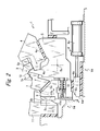
- the bending blade 4c of the aerial cam 4 presses the workpiece 12 held between the bending blade 4c and the bending part 5a of the rotary cam 5 to effect deep bending (see Fig. 2 ).
- the upper die 2 further moves upward, so that the upper die driver 11 and the aerial cam 4 move upward.
- the slide block 6b is moved rightward by the air cylinder 6a of the drive unit 6. Accordingly, the rotary cam 5 rotates about the rotational center 5c counterclockwise, causing the bending part 5a to move away from inside the workpiece 12.
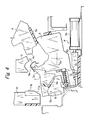
- sufficient space for panel removal is secured under the workpiece 12, as shown in Fig. 4 . Therefore, such negative angle forming with deep bending is possible.
- the die 1 When the workpiece 12 after bending is removed from the die 1, the die 1 returns to the initial state shown in Fig. 1 .
- the slide body 7 which has the hold part 7a constituting a part of a male die for workpiece forming, and slides in the up and down direction is provided at the rotary cam 5, so that when the workpiece is subjected to bending, the hold part 7a is separated from the workpiece 12 first and the bending part 5a is rotated into the space formed by the separation of the hold part 7a so as to be separated from the workpiece 12.
- a negative-angle press-working die 1a includes a slide body 7 having a fixed punch 16 and a hold part 7a and being slidable obliquely upward and downward with respect to a workpiece 12a, a rotary cam 5 having a bending part 5a, and a slide cam 4d supported at a lower die and laterally slidable on the rotary cam 5, with a rotational center 5c set at a proper position.
- This structure can cause the rotary cam 5 to rotate counterclockwise to move the bending part 5a away from the bottom surface of the workpiece 12a, thus securing a panel removal clearance, as in the above-described embodiment.
Landscapes
- Engineering & Computer Science (AREA)
- Mechanical Engineering (AREA)
- Mounting, Exchange, And Manufacturing Of Dies (AREA)
- Bending Of Plates, Rods, And Pipes (AREA)
Applications Claiming Priority (1)
| Application Number | Priority Date | Filing Date | Title |
|---|---|---|---|
| JP2007288585A JP5014069B2 (ja) | 2007-11-06 | 2007-11-06 | プレス成形用金型 |
Publications (2)
| Publication Number | Publication Date |
|---|---|
| EP2058061A1 true EP2058061A1 (fr) | 2009-05-13 |
| EP2058061B1 EP2058061B1 (fr) | 2010-05-19 |
Family
ID=40379826
Family Applications (1)
| Application Number | Title | Priority Date | Filing Date |
|---|---|---|---|
| EP08011615A Not-in-force EP2058061B1 (fr) | 2007-11-06 | 2008-06-26 | Outil de formage pour pliage angulaire negatif |
Country Status (6)
| Country | Link |
|---|---|
| US (1) | US7665341B2 (fr) |
| EP (1) | EP2058061B1 (fr) |
| JP (1) | JP5014069B2 (fr) |
| KR (1) | KR20090046676A (fr) |
| CN (1) | CN101428315A (fr) |
| DE (1) | DE602008001300D1 (fr) |
Cited By (9)
| Publication number | Priority date | Publication date | Assignee | Title |
|---|---|---|---|---|
| KR100971354B1 (ko) | 2009-12-28 | 2010-07-20 | 주식회사 현대알비 | 플레이트 에지 밴딩 머신 |
| EP2431108A1 (fr) * | 2010-09-17 | 2012-03-21 | Yourbusiness Co., Ltd. | Ensamble de matrice de presse |
| WO2012075363A1 (fr) * | 2010-12-02 | 2012-06-07 | Norgren Automation Solutions, Inc. | Outil de pliage avec unité de came radiale |
| EP2705913A1 (fr) * | 2012-09-10 | 2014-03-12 | Peugeot Citroën Automobiles Sa | Outil de presse pour l'emboutissage d'une tôle |
| DE102012210960A1 (de) | 2012-06-27 | 2014-04-03 | Bayerische Motoren Werke Aktiengesellschaft | Füllschieberanordnung für ein pressengebundenes Blechbearbeitungswerkzeug und pressengebundenes Blechbearbeitungswerkzeug mit solcher Füllschieberanordnung |
| FR3024380A1 (fr) * | 2014-08-04 | 2016-02-05 | Peugeot Citroen Automobiles Sa | Presse d’emboutissage permettant d’emboutir une piece en tole de section en contre-depouille |
| FR3027828A1 (fr) * | 2014-10-30 | 2016-05-06 | Peugeot Citroen Automobiles Sa | Outillage de mise a forme d’un bord en contre-depouille d’embouti |
| FR3031322A1 (fr) * | 2015-01-06 | 2016-07-08 | Peugeot Citroen Automobiles Sa | Mise a forme d’un bord d’embouti avec renvoi en contre-depouille |
| EP3100795A1 (fr) | 2015-06-03 | 2016-12-07 | Peugeot Citroën Automobiles SA | Poincon de mise a forme par emboutissage d'un bord en contre depouille d'embouti |
Families Citing this family (28)
| Publication number | Priority date | Publication date | Assignee | Title |
|---|---|---|---|---|
| US20080237961A1 (en) * | 2007-03-30 | 2008-10-02 | Honda Motor Co., Ltd. | Pad for holding blank and die assembly therewith |
| US8516874B2 (en) * | 2007-12-27 | 2013-08-27 | Toyota Motor Engineering & Manufacturing North America, Inc. | Pillar for motor vehicle and tool for making the same |
| JP5152047B2 (ja) * | 2009-03-11 | 2013-02-27 | トヨタ自動車株式会社 | プレス装置 |
| DE102010018534A1 (de) * | 2010-04-27 | 2011-10-27 | Läpple Werkzeugbau GmbH | Vorrichtung zum Formen eines Werkstücks |
| US8371150B2 (en) * | 2010-11-09 | 2013-02-12 | Cheng Uei Precision Industry Co., Ltd. | Forming die |
| CN103747891B (zh) | 2011-08-19 | 2015-10-14 | 麦格纳国际公司 | 用于高温成形工具的自补偿式可收缩型芯 |
| KR101167042B1 (ko) * | 2012-01-04 | 2012-07-31 | 주식회사 루보 | 부각 성형 장치 |
| KR101455673B1 (ko) * | 2012-11-06 | 2014-10-28 | 주식회사 성우하이텍 | 캠 프레스 장치 |
| CN102962358A (zh) * | 2012-11-22 | 2013-03-13 | 奇瑞汽车股份有限公司 | 一种旋转式子母斜楔模具 |
| CN103357762B (zh) * | 2013-07-18 | 2015-05-20 | 上海大众汽车有限公司 | 三层叠加变向斜楔机构及冲压模具和冲压方法 |
| CN103433390B (zh) * | 2013-07-25 | 2015-12-23 | 柳州职业技术学院 | 一种旋转斜楔 |
| KR101550619B1 (ko) * | 2013-12-30 | 2015-09-07 | 현대자동차 주식회사 | 프레스 장치 |
| CN104043718B (zh) * | 2014-06-26 | 2016-04-20 | 梧州恒声电子科技有限公司 | 一种可调节大小的盆架类产品的斜冲花模具结构 |
| CN104190790B (zh) * | 2014-08-13 | 2016-08-24 | 奇瑞汽车股份有限公司 | 一种三动作子母斜楔模具及其控制方法 |
| CN104722659B (zh) * | 2015-03-17 | 2017-03-08 | 安徽江淮汽车集团股份有限公司 | 旋转斜楔机构及冲压模具 |
| KR101655668B1 (ko) | 2015-04-20 | 2016-09-07 | 기아자동차주식회사 | 캠형 프레스 |
| JP6517622B2 (ja) * | 2015-07-31 | 2019-05-22 | ダイハツ工業株式会社 | ルーフサイドレール |
| KR101714256B1 (ko) * | 2015-11-04 | 2017-03-08 | 현대자동차주식회사 | 도어 인너 패널의 버링 홀 가공용 스위블 지그 캠 및 그 작동방법 |
| CN108348975A (zh) * | 2015-12-21 | 2018-07-31 | 标致雪铁龙汽车股份有限公司 | 具有在同一压制行程下操作的组合滑块的压制工具 |
| US10486216B2 (en) | 2016-10-17 | 2019-11-26 | Ford Motor Company | Draw die and binder lock |
| JP7014131B2 (ja) * | 2018-11-07 | 2022-02-01 | トヨタ車体株式会社 | ロータリーカム式曲げ・寄曲げ複合金型 |
| KR102173558B1 (ko) * | 2020-03-11 | 2020-11-03 | 김종열 | 자동차의 로어 암용 더블캠 프레스금형 |
| CN114472717A (zh) * | 2022-02-22 | 2022-05-13 | 四川成飞集成科技股份有限公司 | 一种能够自动移动的滑车机构 |
| CN115194020B (zh) * | 2022-06-22 | 2024-08-06 | 鹤壁天淇汽车模具有限公司 | 隐藏式汽车覆盖件模具自平衡反向翻整装置及工作方法 |
| CN117733010A (zh) * | 2023-12-27 | 2024-03-22 | 安徽千缘模具有限公司 | 带有动作时序转换机构的模具 |
| CN118719955B (zh) * | 2024-07-30 | 2026-04-07 | 奇瑞汽车股份有限公司 | 侧围后盖流水槽翻边的成型模具及成型工艺 |
| CN118847790B (zh) * | 2024-07-31 | 2025-11-28 | 江铃汽车股份有限公司 | 一种柔性回程的旋转斜楔结构 |
| CN121649272A (zh) * | 2026-02-06 | 2026-03-13 | 中建五局西南建设投资有限公司 | 一种双拼槽钢加工设备 |
Citations (5)
| Publication number | Priority date | Publication date | Assignee | Title |
|---|---|---|---|---|
| JPS59197318A (ja) | 1983-04-21 | 1984-11-08 | Daihatsu Motor Co Ltd | プレス用金型 |
| JP2000271649A (ja) * | 1999-03-24 | 2000-10-03 | Toyota Motor Corp | プレス装置 |
| EP1044739A2 (fr) * | 1999-04-15 | 2000-10-18 | Umix Co., Ltd. | Matrices de formage d'angle négatif et son appareil de pressage |
| EP1698409A1 (fr) * | 2005-03-02 | 2006-09-06 | Bayerische Motoren Werke Aktiengesellschaft | Dispositif pour une presse pour le façonnage d'une tôle avec une section deformable contre une forme avec une contre-dépouille séparée du dispositif |
| EP1847371A2 (fr) * | 2006-04-17 | 2007-10-24 | Yourbusiness Co., Ltd. | Structure de palier et appareil de moulage ayant cette structure |
Family Cites Families (5)
| Publication number | Priority date | Publication date | Assignee | Title |
|---|---|---|---|---|
| JP2001137946A (ja) * | 1999-11-09 | 2001-05-22 | Toyota Motor Corp | 成形型 |
| JP2004066314A (ja) * | 2002-08-08 | 2004-03-04 | Your Business:Kk | プレス成形装置 |
| JP4162579B2 (ja) * | 2003-11-27 | 2008-10-08 | 株式会社ユアビジネス | 負角成形金型 |
| JP2006116558A (ja) * | 2004-10-20 | 2006-05-11 | Your Business:Kk | 金属板のプレス成形装置 |
| US7624615B2 (en) * | 2006-10-27 | 2009-12-01 | Chrysler Group Llc | Wedge activated rotating filler cam |
-
2007
- 2007-11-06 JP JP2007288585A patent/JP5014069B2/ja not_active Expired - Fee Related
-
2008
- 2008-06-18 US US12/213,335 patent/US7665341B2/en not_active Expired - Fee Related
- 2008-06-26 EP EP08011615A patent/EP2058061B1/fr not_active Not-in-force
- 2008-06-26 DE DE602008001300T patent/DE602008001300D1/de active Active
- 2008-07-17 KR KR1020080069601A patent/KR20090046676A/ko not_active Withdrawn
- 2008-07-17 CN CNA2008101379679A patent/CN101428315A/zh active Pending
Patent Citations (5)
| Publication number | Priority date | Publication date | Assignee | Title |
|---|---|---|---|---|
| JPS59197318A (ja) | 1983-04-21 | 1984-11-08 | Daihatsu Motor Co Ltd | プレス用金型 |
| JP2000271649A (ja) * | 1999-03-24 | 2000-10-03 | Toyota Motor Corp | プレス装置 |
| EP1044739A2 (fr) * | 1999-04-15 | 2000-10-18 | Umix Co., Ltd. | Matrices de formage d'angle négatif et son appareil de pressage |
| EP1698409A1 (fr) * | 2005-03-02 | 2006-09-06 | Bayerische Motoren Werke Aktiengesellschaft | Dispositif pour une presse pour le façonnage d'une tôle avec une section deformable contre une forme avec une contre-dépouille séparée du dispositif |
| EP1847371A2 (fr) * | 2006-04-17 | 2007-10-24 | Yourbusiness Co., Ltd. | Structure de palier et appareil de moulage ayant cette structure |
Cited By (21)
| Publication number | Priority date | Publication date | Assignee | Title |
|---|---|---|---|---|
| KR100971354B1 (ko) | 2009-12-28 | 2010-07-20 | 주식회사 현대알비 | 플레이트 에지 밴딩 머신 |
| EP2431108A1 (fr) * | 2010-09-17 | 2012-03-21 | Yourbusiness Co., Ltd. | Ensamble de matrice de presse |
| US9327330B2 (en) | 2010-12-02 | 2016-05-03 | Norgren Automation Solutions, Llc | Bending die with radial cam unit |
| WO2012075363A1 (fr) * | 2010-12-02 | 2012-06-07 | Norgren Automation Solutions, Inc. | Outil de pliage avec unité de came radiale |
| CN103260782A (zh) * | 2010-12-02 | 2013-08-21 | 诺冠自动化解决方案有限责任公司 | 具有径向凸轮单元的弯曲模 |
| US8789402B2 (en) | 2010-12-02 | 2014-07-29 | Norgren Automation Solutions, Llc | Bending die with radial cam unit |
| CN103260782B (zh) * | 2010-12-02 | 2015-04-22 | 诺冠自动化解决方案有限责任公司 | 具有径向凸轮单元的弯曲模 |
| US9032771B2 (en) | 2010-12-02 | 2015-05-19 | Norgren Automation Solutions, Llc | Bending die with radial cam unit |
| DE102012210960A1 (de) | 2012-06-27 | 2014-04-03 | Bayerische Motoren Werke Aktiengesellschaft | Füllschieberanordnung für ein pressengebundenes Blechbearbeitungswerkzeug und pressengebundenes Blechbearbeitungswerkzeug mit solcher Füllschieberanordnung |
| DE102012210960B4 (de) | 2012-06-27 | 2024-02-29 | Bayerische Motoren Werke Aktiengesellschaft | Füllschieberanordnung für ein pressengebundenes Blechbearbeitungswerkzeug und pressengebundenes Blechbearbeitungswerkzeug mit solcher Füllschieberanordnung |
| EP2705913A1 (fr) * | 2012-09-10 | 2014-03-12 | Peugeot Citroën Automobiles Sa | Outil de presse pour l'emboutissage d'une tôle |
| FR2995232A1 (fr) * | 2012-09-10 | 2014-03-14 | Peugeot Citroen Automobiles Sa | Outil de presse pour l'emboutissage d'une tole |
| FR3024380A1 (fr) * | 2014-08-04 | 2016-02-05 | Peugeot Citroen Automobiles Sa | Presse d’emboutissage permettant d’emboutir une piece en tole de section en contre-depouille |
| WO2016020594A1 (fr) * | 2014-08-04 | 2016-02-11 | Peugeot Citroen Automobiles Sa | Presse d'emboutissage permettant d'emboutir une pièce en tôle de section en contre-dépouille |
| FR3027828A1 (fr) * | 2014-10-30 | 2016-05-06 | Peugeot Citroen Automobiles Sa | Outillage de mise a forme d’un bord en contre-depouille d’embouti |
| FR3031322A1 (fr) * | 2015-01-06 | 2016-07-08 | Peugeot Citroen Automobiles Sa | Mise a forme d’un bord d’embouti avec renvoi en contre-depouille |
| WO2016110621A1 (fr) * | 2015-01-06 | 2016-07-14 | Peugeot Citroen Automobiles Sa | Outillage et procédé de mise a forme d'un bord d'embouti avec renvoi en contre-depouille |
| CN107107143A (zh) * | 2015-01-06 | 2017-08-29 | 标致雪铁龙集团 | 在底切处具有凹进部的冲压件的边缘的成型工具及方法 |
| CN107107143B (zh) * | 2015-01-06 | 2020-03-10 | 标致雪铁龙集团 | 在底切处具有凹进部的冲压件的边缘的成型工具及方法 |
| EP3100795A1 (fr) | 2015-06-03 | 2016-12-07 | Peugeot Citroën Automobiles SA | Poincon de mise a forme par emboutissage d'un bord en contre depouille d'embouti |
| FR3036987A1 (fr) * | 2015-06-03 | 2016-12-09 | Peugeot Citroen Automobiles Sa | Poincon de mise a forme par emboutissage d’un bord en contre depouille d’embouti. |
Also Published As
| Publication number | Publication date |
|---|---|
| EP2058061B1 (fr) | 2010-05-19 |
| US7665341B2 (en) | 2010-02-23 |
| JP5014069B2 (ja) | 2012-08-29 |
| DE602008001300D1 (de) | 2010-07-01 |
| CN101428315A (zh) | 2009-05-13 |
| JP2009113078A (ja) | 2009-05-28 |
| US20090113978A1 (en) | 2009-05-07 |
| KR20090046676A (ko) | 2009-05-11 |
Similar Documents
| Publication | Publication Date | Title |
|---|---|---|
| EP2058061B1 (fr) | Outil de formage pour pliage angulaire negatif | |
| EP1535674B1 (fr) | Outillage de formage d'une presse pour pliage angulaire négatif | |
| US5784916A (en) | Thin sheet forming die assembly including a lower die having plural parallel rotating cylindrical members | |
| CN205519196U (zh) | 与冲压方向成负角度的修边冲孔斜楔 | |
| JP2015136728A (ja) | 複合プレス型のカム装置および複合プレス加工方法 | |
| JP5098671B2 (ja) | プレス型のスクラップ排出装置 | |
| CN106825231B (zh) | 再成型板形工件一部分的冲压机床的工具及其使用方法 | |
| CN102814382B (zh) | 冲孔和矫平金属板的方法及其工具 | |
| CN204603011U (zh) | 一种管件的压扁和冲孔机构 | |
| JP2016198810A (ja) | ヘミング加工方法 | |
| EP2379318B1 (fr) | Poinçon | |
| JP6619595B2 (ja) | プレス加工機 | |
| CN109789472A (zh) | 用于加工板状工件的工具和机床以及方法 | |
| JP2005246410A (ja) | プレス型 | |
| CN101773966B (zh) | 一种齿轮式折弯模具 | |
| EP3147044B1 (fr) | Procédé et appareil de forgeage de matériau hétérogène | |
| EP2822713B1 (fr) | Outil pour l'emboutissage et le tombage de bords d'un capot d'un vehicule | |
| JP2669141B2 (ja) | 突上げ塑性加工装置 | |
| CN109648339A (zh) | 一种板件成型切断一体化设备 | |
| CN212443573U (zh) | 一种工件的局部变薄模具 | |
| CN114206521B (zh) | 用于加工板状工件的工具和方法 | |
| US9757783B2 (en) | Method and machine for bending metal | |
| CN110270625B (zh) | 双动模架装置 | |
| JP2008260060A (ja) | 負角成形型 | |
| CN111822788A (zh) | 一种工件的局部变薄模具及成型控制方法 |
Legal Events
| Date | Code | Title | Description |
|---|---|---|---|
| PUAI | Public reference made under article 153(3) epc to a published international application that has entered the european phase |
Free format text: ORIGINAL CODE: 0009012 |
|
| AK | Designated contracting states |
Kind code of ref document: A1 Designated state(s): AT BE BG CH CY CZ DE DK EE ES FI FR GB GR HR HU IE IS IT LI LT LU LV MC MT NL NO PL PT RO SE SI SK TR |
|
| AX | Request for extension of the european patent |
Extension state: AL BA MK RS |
|
| 17P | Request for examination filed |
Effective date: 20090610 |
|
| GRAP | Despatch of communication of intention to grant a patent |
Free format text: ORIGINAL CODE: EPIDOSNIGR1 |
|
| AKX | Designation fees paid |
Designated state(s): DE FR IT |
|
| GRAS | Grant fee paid |
Free format text: ORIGINAL CODE: EPIDOSNIGR3 |
|
| GRAA | (expected) grant |
Free format text: ORIGINAL CODE: 0009210 |
|
| AK | Designated contracting states |
Kind code of ref document: B1 Designated state(s): DE FR IT |
|
| REF | Corresponds to: |
Ref document number: 602008001300 Country of ref document: DE Date of ref document: 20100701 Kind code of ref document: P |
|
| PGFP | Annual fee paid to national office [announced via postgrant information from national office to epo] |
Ref country code: FR Payment date: 20100630 Year of fee payment: 3 |
|
| PGFP | Annual fee paid to national office [announced via postgrant information from national office to epo] |
Ref country code: DE Payment date: 20100729 Year of fee payment: 3 |
|
| PLBE | No opposition filed within time limit |
Free format text: ORIGINAL CODE: 0009261 |
|
| STAA | Information on the status of an ep patent application or granted ep patent |
Free format text: STATUS: NO OPPOSITION FILED WITHIN TIME LIMIT |
|
| PG25 | Lapsed in a contracting state [announced via postgrant information from national office to epo] |
Ref country code: IT Free format text: LAPSE BECAUSE OF FAILURE TO SUBMIT A TRANSLATION OF THE DESCRIPTION OR TO PAY THE FEE WITHIN THE PRESCRIBED TIME-LIMIT Effective date: 20100519 |
|
| 26N | No opposition filed |
Effective date: 20110222 |
|
| REG | Reference to a national code |
Ref country code: DE Ref legal event code: R097 Ref document number: 602008001300 Country of ref document: DE Effective date: 20110221 |
|
| REG | Reference to a national code |
Ref country code: FR Ref legal event code: ST Effective date: 20120229 |
|
| REG | Reference to a national code |
Ref country code: DE Ref legal event code: R119 Ref document number: 602008001300 Country of ref document: DE Effective date: 20120103 |
|
| PG25 | Lapsed in a contracting state [announced via postgrant information from national office to epo] |
Ref country code: FR Free format text: LAPSE BECAUSE OF NON-PAYMENT OF DUE FEES Effective date: 20110630 Ref country code: DE Free format text: LAPSE BECAUSE OF NON-PAYMENT OF DUE FEES Effective date: 20120103 |