EP2058065A1 - Niedrigdruck-beschichtungsverfahren und niedrigdruck-beschichtungsvorrichtung - Google Patents
Niedrigdruck-beschichtungsverfahren und niedrigdruck-beschichtungsvorrichtung Download PDFInfo
- Publication number
- EP2058065A1 EP2058065A1 EP07829594A EP07829594A EP2058065A1 EP 2058065 A1 EP2058065 A1 EP 2058065A1 EP 07829594 A EP07829594 A EP 07829594A EP 07829594 A EP07829594 A EP 07829594A EP 2058065 A1 EP2058065 A1 EP 2058065A1
- Authority
- EP
- European Patent Office
- Prior art keywords
- plunger
- vacuum
- inlet
- plunger sleeve
- vacuum chamber
- Prior art date
- Legal status (The legal status is an assumption and is not a legal conclusion. Google has not performed a legal analysis and makes no representation as to the accuracy of the status listed.)
- Granted
Links
Images


Classifications
-
- B—PERFORMING OPERATIONS; TRANSPORTING
- B22—CASTING; POWDER METALLURGY
- B22D—CASTING OF METALS; CASTING OF OTHER SUBSTANCES BY THE SAME PROCESSES OR DEVICES
- B22D17/00—Pressure die casting or injection die casting, i.e. casting in which the metal is forced into a mould under high pressure
- B22D17/14—Machines with evacuated die cavity
- B22D17/145—Venting means therefor
-
- B—PERFORMING OPERATIONS; TRANSPORTING
- B22—CASTING; POWDER METALLURGY
- B22D—CASTING OF METALS; CASTING OF OTHER SUBSTANCES BY THE SAME PROCESSES OR DEVICES
- B22D17/00—Pressure die casting or injection die casting, i.e. casting in which the metal is forced into a mould under high pressure
- B22D17/08—Cold chamber machines, i.e. with unheated press chamber into which molten metal is ladled
- B22D17/10—Cold chamber machines, i.e. with unheated press chamber into which molten metal is ladled with horizontal press motion
-
- B—PERFORMING OPERATIONS; TRANSPORTING
- B22—CASTING; POWDER METALLURGY
- B22D—CASTING OF METALS; CASTING OF OTHER SUBSTANCES BY THE SAME PROCESSES OR DEVICES
- B22D17/00—Pressure die casting or injection die casting, i.e. casting in which the metal is forced into a mould under high pressure
- B22D17/14—Machines with evacuated die cavity
-
- B—PERFORMING OPERATIONS; TRANSPORTING
- B22—CASTING; POWDER METALLURGY
- B22D—CASTING OF METALS; CASTING OF OTHER SUBSTANCES BY THE SAME PROCESSES OR DEVICES
- B22D17/00—Pressure die casting or injection die casting, i.e. casting in which the metal is forced into a mould under high pressure
- B22D17/20—Accessories: Details
-
- B—PERFORMING OPERATIONS; TRANSPORTING
- B22—CASTING; POWDER METALLURGY
- B22D—CASTING OF METALS; CASTING OF OTHER SUBSTANCES BY THE SAME PROCESSES OR DEVICES
- B22D17/00—Pressure die casting or injection die casting, i.e. casting in which the metal is forced into a mould under high pressure
- B22D17/20—Accessories: Details
- B22D17/2015—Means for forcing the molten metal into the die
- B22D17/2023—Nozzles or shot sleeves
-
- B—PERFORMING OPERATIONS; TRANSPORTING
- B22—CASTING; POWDER METALLURGY
- B22D—CASTING OF METALS; CASTING OF OTHER SUBSTANCES BY THE SAME PROCESSES OR DEVICES
- B22D17/00—Pressure die casting or injection die casting, i.e. casting in which the metal is forced into a mould under high pressure
- B22D17/20—Accessories: Details
- B22D17/22—Dies; Die plates; Die supports; Cooling equipment for dies; Accessories for loosening and ejecting castings from dies
- B22D17/2227—Die seals
Definitions
- the present invention relates to vacuum die casting methods and vacuum die casting apparatuses.
- JPA-2002-224807 discloses such an art.
- the opening of the end of the plunger sleeve is closed by sliding a vacuum sleeve in the plunger sleeve, which results in deformation or expansion caused by the heat of the plunger sleeve. So, the distance, between the vacuum sleeve and plunger sleeve, changes. As a result, the seal performance will be degraded.
- the molten metal With regard to the opening of the molten metal inlet, the molten metal will flow over around the inlet. So, the shutter or the like provided with the opening may fail to sufficiently seal the opening.
- the evacuation time may be around one second. Therefore, one can easily understand that the degree of vacuum is not homogeneous in the space.
- the objective of the present invention is to provide a vacuum die casting method and a vacuum die casting apparatus enable to solve the problems regarding the seal performance, pressure differential, and the stability of the degree of vacuum.
- the first embodiment of the present invention is a vacuum die casting method carrying out the casting with evacuation of a casting cavity, in which a molten metal is poured from a molten metal inlet of a plunger sleeve, followed by forming a vacuum chamber surrounding the inlet and an open end of the plunger sleeve that is on the opposite side of the die, and an evacuation of the vacuum chamber and the cavity starts before an operation of a plunger tip starts.
- the plunger tip is positioned between the open end of the plunger sleeve and the inlet so that the vacuum chamber is communicated to the inside of the plunger sleeve through the inlet.
- the second embodiment of the present invention is a vacuum die casting apparatus comprising a closure member forming a vacuum chamber surrounding the inlet and an open end of the plunger sleeve that is on the opposite side of the die, in which a molten metal is poured from a molten metal inlet of a plunger sleeve, followed by forming a vacuum chamber by utilizing the closure member, and an evacuation of the vacuum chamber and the cavity starts before an operation of a plunger tip starts.
- the plunger tip is positioned between the open end of the plunger sleeve and the inlet so that the vacuum chamber is communicated to the inside of the plunger sleeve through the inlet.
- the closure member is formed in a tubular shape, having an open end at one side to which the plunger tip moves in an injection and having a closed end provided with a hole into which a shaft of the plunger tip inserts.
- the internal dimension of the closure member is larger than the external dimension of the plunger sleeve.
- the plunger sleeve is provided with a flange at an outer surface thereof, and the vacuum chamber is formed by pressing and fixing the open end of the closure member to the flange.
- a fixing platen of the casting die is provided with a flange, and the vacuum chamber is formed by pressing and fixing the open end of the closure member to the flange.
- the closure member, the plunger sleeve, the plunger tip and the shaft are arranged coaxially.
- evacuation starts earlier, and after starting the evacuation, the efficient evacuation can be achieved.
- the plunger sleeve and casting cavity can be evacuated in a short period.
- the evacuation to the desired level can be operated with stability.
- the space of the front side and backside of the plunger tip is expected to be substantially equally evacuated via the inlet before the plunger tip is operated for injection. Consequently, the presence of pressure differential between the spaces is prevented. Accordingly, the problems are avoided, such as the penetration of the molten metal into the gap between the plunger tip and plunger sleeve.
- evacuation starts earlier, and after starting the evacuation, the efficient evacuation can be achieved.
- the plunger sleeve and casting cavity can be evacuated in a short period.
- the evacuation to the desired level can be operated with stability.
- the space of the front side and backside of the plunger tip seem to be substantially equally evacuated via the inlet before the plunger tip is operated for injection, so that the presence of pressure differential between the spaces is prevented. Accordingly, the problems are avoided, such as the penetration of the molten metal into the gap between the plunger tip and plunger sleeve.
- the present invention enables the apparatus to be smaller.
- the flange can serve as a stopper of the closure member and as a seal member of the vacuum chamber. Without touching the plunger sleeve and inlet, the vacuum chamber can be formed at the side of the open end of the plunger sleeve. Additionally, the flange can securely seal regardless of the thermal strain of the plunger sleeve or the dirtiness of the inlet.
- the vacuum die casting apparatus can be downsized.
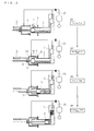
- FIGS. 1(a) and 1(b) illustrate a vacuum die casting apparatus 30.
- a casting die 1 is provided with a plunger sleeve 2 through a fixed platen (not shown).
- a plunger tip 3 slides to press a molten metal 5 into a casting cavity 4, which is defined in the casting die 1.
- the plunger sleeve 2 has a molten metal inlet 6 where the molten metal 5 is poured into the plunger sleeve 2 from a ladle 7.
- the plunger sleeve 2 is provided with a flange 8 at the outer surface thereof.
- the flange 8 is arranged to form the face, which is substantially rectangular with respect to the actuating direction of the plunger tip 3.
- the flange 8 is disposed between the inlet 6 and the casting die 1; in other words, the flange 8 is displaced from the inlet 6 toward the injection direction of the plunger tip 3 to press the molten metal.
- the plunger tip 3 is provided with a shaft 9.
- the shaft 9 is coaxially provided with a closure member 10, which defines a vacuum chamber 11.
- the closure member 10 is formed in a tubular shape and has an open end 10a and a closed end 10d.
- the open end 10a is arranged to face to the flange 8.
- the closed end 10d has a hole 10c where the shaft 9 slidably penetrates.
- the internal dimension of the closure member 10 is larger than the external dimension of the plunger sleeve 2.
- the open end 10a of the closure member 10 is moved toward the injection direction of the plunger tip, and then an open end 2a of the plunger sleeve 2 is inserted into the closure member 10.
- the open end 10a of the closure member 10 is provided with a flange 10b.
- the vacuum chamber 11 is defined surrounding the open end 2a of the plunger sleeve 2.
- the closure member 10, the plunger sleeve 2, the plunger tip 3, and the shaft 9 are arranged coaxially, so that the vacuum die casting apparatus 30 is downsized.
- the shaft 9 is actuated with the actuator (not shown), e.g. an air cylinder or a hydraulic cylinder.
- the actuator e.g. an air cylinder or a hydraulic cylinder.
- the plunger tip 3 arranged at the tip of the shaft 9 slides telescopically in the plunger sleeve 2.
- the shaft 9 is slidably fitted into the hole 10c formed at the closed end 10d of the closure member 10.
- the hole 10c is provided with a seal member 12, e.g. an O-ring.
- the closure member 10 is actuated by an actuator 13, e.g. an air cylinder or a hydraulic cylinder, to keep coaxial with respect to the plunger tip 3 or the shaft 9.
- an actuator 13 e.g. an air cylinder or a hydraulic cylinder
- the actuator 13 is controlled independently regarding the plunger tip 3 or the shaft 9, so that the closure member 10 and the plunger tip 3 move independently from each other.
- seal member 14 e.g. an O-ring, at the face of the flange 8 facing to the flange 10b of the closure member 10.
- seal member 14 seals the clearance between them. It should be noted that the seal member 14 could be provided at the flange 10b.
- the flanges 8 and 10 serve as a stopper of the closure member 10 and as a seal material of the vacuum chamber 11.
- the closure member 10 moves outside of the plunger sleeve 2, so the lubricant is unnecessary between them.
- the seal material composed of the flanges 8 and 10 is disposed outside of the plunger sleeve 2, so the flanges 8 and 10 are prevented from thermal deformation caused by the heat of the molten metal. As a result, the seal performance is secured.
- the closure member 10 defines the vacuum chamber 11 without contacting the inlet 6, so the problems are avoided; such as degradation of the seal performance caused by the metal molten adheres to the inlet 6. As a result, the required degree of vacuum is secured, and maintenance-free seal is realized.
- the closure member 10 is provided with a vacuum opening 15 for evacuation of the vacuum chamber 11.
- the vacuum opening 15 could be disposed at the flange 8.
- the vacuum chamber can be evacuated through the vacuum opening 15.
- the pipe installation connecting to a vacuum tank 18 is fastened.
- the casting die 1 is provided with a vacuum opening 16, which communicates into the cavity 4 and evacuates the cavity 4.
- the path from the cavity 4 and the vacuum opening 16 has a shut valve 17.
- the vacuum openings 15 and 16 are connected with a vacuum pump 19 through a valve 20 and the vacuum tank 18. Operating the valve 20 starts the evacuation of the cavity 4 and vacuum chamber 11. In this case, the vacuum tank 18 works as a buffer.
- the ladle 7 is moved backward, at the same time the actuator 13 actuates the closure member 10 forward to contact to the flange 8, and then the vacuum chamber 11 is formed.
- the plunger tip 3 is moved backward, at the same time or followed by actuating the closure member 10 backward.
- the closure member 10 is moved backward by the actuator 13 to separate from the plunger sleeve 2.
- the plunger tip 3 is disposed so as to position the tip thereof at the backside of the inlet 6, so that the inlet 6 is completely open.
- the valve 20 is closed and the evacuation is not started.
- the closure member 10 is pressed and contacted to the flange 8 of the plunger sleeve 2 by the actuator 13.
- the open end 2a of the plunger sleeve 2 and the inlet 6 are disposed in the vacuum chamber 11 of the closure member 10.
- the space backside of the plunger tip 3 (the opposite side with respect to the side where the molten metal touches) is communicated to the space in the plunger sleeve 2 via the inlet 6.
- the plunger tip 3 is positioned between the open end 2a of the plunger sleeve 2 and the inlet 6.
- the vacuum chamber 11 is communicated to the inside of the plunger sleeve 2 via the inlet 6.
- the molten metal poured with ladle 7 waves so that it is laid for a brief period (e.g. one or two minutes) to smooth the molten metal.
- valve 20 In smoothing the molten metal or after finishing the smoothing, the valve 20 is opened, and then the evacuation of the vacuum chamber 11 and cavity 4 is started.
- the evacuation will be started before the plunger tip 3 is actuated to inject the molten metal.
- the evacuation is started before the plunger tip 3 shut the inlet 6.
- the vacuum chamber 11 is communicated to the plunger sleeve 2 via the inlet 6, so that the air in the plunger sleeve 2 is evacuated through the cavity 4 and the inlet 6.
- the start timing of evacuation of the plunger sleeve 2 is set before starting the injection of the plunger tip 3. Therefore, the plunger sleeve 2 can be evacuated through both of the cavity 4 and inlet 6.
- the start timing of evacuation is forwarded and effective evacuation is achieved after starting the evacuation. Therefore, the plunger sleeve 2 and cavity 4 are evacuated in a short period, or the evacuation period becomes longer.
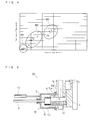
- Comparing the evacuation curves L1 and L2 shown in FIG. 3 can represent the effects of the vacuum die casting method. It should be noticed that the evacuation curves are plotted by the low-speed injection, not by the high-speed injection, to compare the degree of vacuum.
- the evacuation curve L1 represents this embodiment according to the present invention and the evacuation curve L2 represents the conventional embodiment.
- the axis of abscissa is time and that of ordinate is pressure in the cavity.
- the evacuation curve L3 represents the position of the plunger tip 3, and the high-speed injection starts at the target time T2.
- the start timing of evacuation can be set at the time T0 (for example, the timing after smoothing the molten metal). That is to say, the evacuation can be started when the plunger tip 3 is positioned in the initial position.
- the evacuation curve L2 in the conventional embodiment in which the evacuation starts after the plunger tip passes through the inlet, the evacuation starts at the time T1, which is later than the time T0, and the pressure at the target time T2 is higher than that of the evacuation curve L2.
- the start timing of evacuation becomes earlier in this embodiment, so the degree of vacuum at the target time T2 can become lower.
- the evacuation is performed through both the cavity 4 and inlet 6. So, the evacuation can be effectively performed, and finally the degree of vacuum will be upgraded.
- the plunger tip 3 is moved by the actuator (not shown), and then the molten metal is injected into the cavity 4, where secures the desired pressure.
- the valve 20 is kept opening, and the evacuation of the cavity 4 and vacuum chamber 11 continues.
- the space inside the plunger sleeve 2 is separated into the space behind the plunger tip 3 and the other space, that is cavity 4 side space.
- the evacuation is carried out through the inlet 6, so the pressures in the both spaces are substantially same. Therefore, the penetration of the molten metal is prevented into the gap between the plunger sleeve 2 and plunger tip 3.
- a completion injection step S4 as shown in FIG. 2 the injection is completed.
- the molten metal is injected with high-speed, and then the shut valve 17 is closed.
- the casting die is opened and the product is removed.
- the plunger tip 3 is replaced after the complete injection step. Accordingly, the backside of the plunger tip 3 sweeps the dusts, chips of metal or the like in the plunger sleeve 2, so that they are removed from the open end 2a of the plunger sleeve 2.
- the molten metal is poured from the molten metal inlet 6 of a plunger sleeve 2, followed by forming the vacuum chamber 11 surrounding the inlet 6 and the open end 2a of the plunger sleeve 2 that is on the opposite side of the casting die 1, and the evacuation of the vacuum chamber 11 and the casting cavity 4 starts before the operation of the plunger tip 3 starts.
- the vacuum die casting apparatus 30 comprises the closure member 10 forming the vacuum chamber 11 surrounding the inlet 6 and the open end of the plunger sleeve 2a that is on the opposite side of the casting die 1 and comprises the vacuum tank 18 and vacuum pump 19 evacuating the vacuum chamber 11 and casting cavity 4.
- the closure member 10 defines the vacuum chamber 11 after the molten metal is poured into the plunger sleeve 2 through the inlet 6.
- the vacuum chamber is evacuated, followed by the injection of the plunger tip 3.
- the start timing of evacuation becomes earlier; after starting the evacuation, the efficient evacuation can be achieved.
- the plunger sleeve 2 and casting cavity 4 can be evacuated in a short period.
- the evacuation to the desired level can be operated with stability.
- the space of the front side and backside of the plunger tip 3 seem to be substantially equally evacuated via the inlet 6 before the plunger tip 3 is injected, so that the presence of pressure differential between the spaces is prevented. Accordingly, the problems are avoided, such as the penetration of the molten metal into the gap between the plunger tip 3 and plunger sleeve 2.
- FIG. 4 shows the relationship between a vacuum degree that is achieved at a target time and a total area of flaw existing in the product, which is cast under the vacuum degree. As shown in FIG. 4 , the total area of flaw in the group M1 where the desired vacuum degree is secured is smaller than the groups M2 and M3 where the desired vacuum degree is not achieved. Carrying out the experiment shows the relationship shown in FIG. 4 .
- the arrangement of the flange 8 is not limited at the outer surface of the plunger sleeve 2.
- the flange 8 can be arranged where it can contact to the flange 10b of the closure member 10 and the flanges 8 and 10b can form the vacuum chamber by pressing and fixing them.
- the flange 8 is provided with the fixing platen 20, to which the casting die 1 is fixed.
- the present invention is applicable to the vacuum die casting methods and vacuum die casting apparatuses.
Landscapes
- Engineering & Computer Science (AREA)
- Mechanical Engineering (AREA)
- Injection Moulding Of Plastics Or The Like (AREA)
- Molds, Cores, And Manufacturing Methods Thereof (AREA)
- Moulds For Moulding Plastics Or The Like (AREA)
- Forging (AREA)
Applications Claiming Priority (2)
| Application Number | Priority Date | Filing Date | Title |
|---|---|---|---|
| JP2006279282A JP4442598B2 (ja) | 2006-10-12 | 2006-10-12 | 減圧鋳造方法、及び、減圧鋳造装置 |
| PCT/JP2007/069856 WO2008044736A1 (en) | 2006-10-12 | 2007-10-11 | Reduced-pressure casting method and reduced-pressure casting device |
Publications (3)
| Publication Number | Publication Date |
|---|---|
| EP2058065A1 true EP2058065A1 (de) | 2009-05-13 |
| EP2058065A4 EP2058065A4 (de) | 2010-02-24 |
| EP2058065B1 EP2058065B1 (de) | 2011-08-17 |
Family
ID=39282926
Family Applications (1)
| Application Number | Title | Priority Date | Filing Date |
|---|---|---|---|
| EP07829594A Ceased EP2058065B1 (de) | 2006-10-12 | 2007-10-11 | Vakkumdruckgussverfahren und vakkumdruckgussvorrichtung |
Country Status (5)
| Country | Link |
|---|---|
| US (1) | US8104528B2 (de) |
| EP (1) | EP2058065B1 (de) |
| JP (1) | JP4442598B2 (de) |
| CN (1) | CN101460269A (de) |
| WO (1) | WO2008044736A1 (de) |
Cited By (1)
| Publication number | Priority date | Publication date | Assignee | Title |
|---|---|---|---|---|
| US11213883B2 (en) | 2018-04-12 | 2022-01-04 | Ahresty Corporation | Casting device, method for manufacturing casting, and seal structure |
Families Citing this family (12)
| Publication number | Priority date | Publication date | Assignee | Title |
|---|---|---|---|---|
| JP5454068B2 (ja) * | 2009-10-08 | 2014-03-26 | トヨタ自動車株式会社 | 真空ダイカスト方法 |
| JP2011147960A (ja) * | 2010-01-20 | 2011-08-04 | Toyota Motor Corp | 減圧鋳造装置および減圧鋳造方法 |
| JP5605792B2 (ja) * | 2010-01-27 | 2014-10-15 | 宇部興産機械株式会社 | 減圧鋳造用給湯装置および給湯方法 |
| CN102145381B (zh) * | 2010-02-09 | 2012-06-20 | 广东鸿泰科技股份有限公司 | 一种高真空压铸用真空装置 |
| JP5726443B2 (ja) * | 2010-06-10 | 2015-06-03 | 株式会社ダイエンジニアリング | 高品質ダイカスト鋳造方法 |
| JP5737100B2 (ja) * | 2011-09-14 | 2015-06-17 | トヨタ自動車株式会社 | 減圧鋳造装置 |
| JP5772683B2 (ja) * | 2012-03-30 | 2015-09-02 | トヨタ自動車株式会社 | 鋳造方法及び鋳造装置 |
| CN102950270B (zh) * | 2012-11-09 | 2014-06-18 | 华中科技大学 | 一种压铸用多向抽真空装置 |
| JP5987674B2 (ja) * | 2012-12-19 | 2016-09-07 | マツダ株式会社 | 鋳造装置および鋳造方法 |
| KR101517571B1 (ko) * | 2014-06-26 | 2015-05-06 | 고동근 | 진공환경에서 금속을 용해하고 성형하는 장치 및 방법 |
| JP7234975B2 (ja) | 2020-02-27 | 2023-03-08 | トヨタ自動車株式会社 | ダイカスト鋳造方法及びダイカスト鋳造装置 |
| EP4219043A1 (de) | 2022-01-26 | 2023-08-02 | Fundación Azterlan | Vakuumdruckverfahren und vorrichtung zum hochdruckgiessen |
Family Cites Families (15)
| Publication number | Priority date | Publication date | Assignee | Title |
|---|---|---|---|---|
| SU656737A2 (ru) | 1977-11-18 | 1979-04-15 | Предприятие П/Я Р-6930 | Устройство дл продувки пресс-форм газом |
| JPS62207554A (ja) * | 1986-03-05 | 1987-09-11 | Kozo Kuroki | 真空ダイカスト装置 |
| US5076344A (en) | 1989-03-07 | 1991-12-31 | Aluminum Company Of America | Die-casting process and equipment |
| US5329983A (en) * | 1991-10-08 | 1994-07-19 | Arnold J. Cook | Sealed chamber die castings of metal matrix components |
| US5860468A (en) * | 1993-07-28 | 1999-01-19 | Cook; Arnold J. | Vacuum die casting |
| WO1998045071A1 (de) * | 1997-04-03 | 1998-10-15 | Yasui, Shouzui | Verfahren und giesseinrichtung für feinguss |
| US6070643A (en) * | 1997-09-12 | 2000-06-06 | Howmet Research Corporation | High vacuum die casting |
| EP1034863A1 (de) * | 1999-03-05 | 2000-09-13 | Alusuisse Technology & Management AG | Verfahren zum Druckgiessen von Leichtmetallen |
| MY130713A (en) * | 2000-01-12 | 2007-07-31 | Nippon Light Metal Co | A die-casting process and a die-casting machine |
| JP2002224807A (ja) | 2001-01-31 | 2002-08-13 | Toyota Motor Corp | 真空ダイカスト装置及び真空ダイカスト方法 |
| JP2002346717A (ja) | 2001-05-17 | 2002-12-04 | Toshiba Mach Co Ltd | 真空ダイカスト装置におけるプランジャチップの周辺構造 |
| JP3620476B2 (ja) | 2001-06-25 | 2005-02-16 | 日産自動車株式会社 | ダイカスト機の射出装置 |
| JP3900422B2 (ja) | 2002-08-09 | 2007-04-04 | 晃由 梅村 | 真空ダイカスト法における給湯方法及びそれに用いる給湯装置 |
| DE102004057325A1 (de) | 2004-11-27 | 2006-06-01 | Pfeiffer Vacuum Gmbh | Vakuumdruckgussverfahren |
| DE102004057324A1 (de) | 2004-11-27 | 2006-06-01 | Pfeiffer Vacuum Gmbh | Vakuumdruckgussverfahren |
-
2006
- 2006-10-12 JP JP2006279282A patent/JP4442598B2/ja not_active Expired - Fee Related
-
2007
- 2007-10-11 EP EP07829594A patent/EP2058065B1/de not_active Ceased
- 2007-10-11 CN CNA2007800210794A patent/CN101460269A/zh active Pending
- 2007-10-11 WO PCT/JP2007/069856 patent/WO2008044736A1/ja not_active Ceased
- 2007-10-11 US US12/296,416 patent/US8104528B2/en not_active Expired - Fee Related
Cited By (1)
| Publication number | Priority date | Publication date | Assignee | Title |
|---|---|---|---|---|
| US11213883B2 (en) | 2018-04-12 | 2022-01-04 | Ahresty Corporation | Casting device, method for manufacturing casting, and seal structure |
Also Published As
| Publication number | Publication date |
|---|---|
| JP2008093712A (ja) | 2008-04-24 |
| US8104528B2 (en) | 2012-01-31 |
| EP2058065B1 (de) | 2011-08-17 |
| CN101460269A (zh) | 2009-06-17 |
| US20090194246A1 (en) | 2009-08-06 |
| WO2008044736A1 (en) | 2008-04-17 |
| JP4442598B2 (ja) | 2010-03-31 |
| EP2058065A4 (de) | 2010-02-24 |
Similar Documents
| Publication | Publication Date | Title |
|---|---|---|
| EP2058065B1 (de) | Vakkumdruckgussverfahren und vakkumdruckgussvorrichtung | |
| CN101954470A (zh) | 压铸机真空压铸系统 | |
| CN104884191A (zh) | 铸造装置及铸造方法 | |
| CN104841906A (zh) | 真空压铸系统及其抽真空方法 | |
| JP2004249334A (ja) | 酸素シールドを用いた高真空ダイカスト法 | |
| AU652909B2 (en) | Vacuum die casting process | |
| CN106457373A (zh) | 用于操作真空压铸机的方法 | |
| KR100870596B1 (ko) | 다이캐스트 장치 및 주조 방법 | |
| JP2016120518A (ja) | ダイカスト方法 | |
| CN1330441C (zh) | 真空铸造用模具 | |
| KR20210013874A (ko) | 고진공 다이캐스팅 금형 | |
| JP5029418B2 (ja) | 減圧鋳造方法、及び、減圧鋳造装置 | |
| JP2014213372A (ja) | ダイキャスト用ガス抜き装置 | |
| JP2000225453A (ja) | ガス抜き装置 | |
| JP5006808B2 (ja) | 射出成形用金型装置 | |
| CN106457374B (zh) | 铸造装置和压铸方法 | |
| CN101219469A (zh) | 滑动装置及该滑动装置所使用的被滑动部件 | |
| CN117733115A (zh) | 挤压铸造模具排气系统及其方法 | |
| JPS6082262A (ja) | 金型用ガス抜き装置 | |
| JP7750482B2 (ja) | ダイカスト製造方法及び装置 | |
| JPH11277214A (ja) | ダイカスト用真空装置 | |
| JP6489500B2 (ja) | 鋳造装置及び鋳造方法 | |
| WO2008088064A1 (ja) | 鋳造方法及びダイカストマシン | |
| JP2002224807A (ja) | 真空ダイカスト装置及び真空ダイカスト方法 | |
| CN118180345A (zh) | 真空压铸方法 |
Legal Events
| Date | Code | Title | Description |
|---|---|---|---|
| PUAI | Public reference made under article 153(3) epc to a published international application that has entered the european phase |
Free format text: ORIGINAL CODE: 0009012 |
|
| 17P | Request for examination filed |
Effective date: 20081007 |
|
| AK | Designated contracting states |
Kind code of ref document: A1 Designated state(s): DE FR |
|
| AX | Request for extension of the european patent |
Extension state: AL BA HR MK RS |
|
| A4 | Supplementary search report drawn up and despatched |
Effective date: 20100125 |
|
| 17Q | First examination report despatched |
Effective date: 20100408 |
|
| GRAP | Despatch of communication of intention to grant a patent |
Free format text: ORIGINAL CODE: EPIDOSNIGR1 |
|
| RTI1 | Title (correction) |
Free format text: VACUUM DIE CASTING METHOD AND VACUUM DIE CASTING DEVICE |
|
| DAX | Request for extension of the european patent (deleted) | ||
| GRAS | Grant fee paid |
Free format text: ORIGINAL CODE: EPIDOSNIGR3 |
|
| GRAA | (expected) grant |
Free format text: ORIGINAL CODE: 0009210 |
|
| AK | Designated contracting states |
Kind code of ref document: B1 Designated state(s): DE FR |
|
| REG | Reference to a national code |
Ref country code: DE Ref legal event code: R096 Ref document number: 602007016633 Country of ref document: DE Effective date: 20111013 |
|
| PLBE | No opposition filed within time limit |
Free format text: ORIGINAL CODE: 0009261 |
|
| STAA | Information on the status of an ep patent application or granted ep patent |
Free format text: STATUS: NO OPPOSITION FILED WITHIN TIME LIMIT |
|
| 26N | No opposition filed |
Effective date: 20120521 |
|
| REG | Reference to a national code |
Ref country code: DE Ref legal event code: R097 Ref document number: 602007016633 Country of ref document: DE Effective date: 20120521 |
|
| REG | Reference to a national code |
Ref country code: DE Ref legal event code: R084 Ref document number: 602007016633 Country of ref document: DE Effective date: 20130717 |
|
| REG | Reference to a national code |
Ref country code: FR Ref legal event code: PLFP Year of fee payment: 10 |
|
| REG | Reference to a national code |
Ref country code: FR Ref legal event code: PLFP Year of fee payment: 11 |
|
| REG | Reference to a national code |
Ref country code: FR Ref legal event code: PLFP Year of fee payment: 12 |
|
| PGFP | Annual fee paid to national office [announced via postgrant information from national office to epo] |
Ref country code: FR Payment date: 20180913 Year of fee payment: 12 |
|
| PGFP | Annual fee paid to national office [announced via postgrant information from national office to epo] |
Ref country code: DE Payment date: 20180925 Year of fee payment: 12 |
|
| REG | Reference to a national code |
Ref country code: DE Ref legal event code: R119 Ref document number: 602007016633 Country of ref document: DE |
|
| PG25 | Lapsed in a contracting state [announced via postgrant information from national office to epo] |
Ref country code: DE Free format text: LAPSE BECAUSE OF NON-PAYMENT OF DUE FEES Effective date: 20200501 |
|
| PG25 | Lapsed in a contracting state [announced via postgrant information from national office to epo] |
Ref country code: FR Free format text: LAPSE BECAUSE OF NON-PAYMENT OF DUE FEES Effective date: 20191031 |