EP2058595A2 - Interface utilisateur pour la commande d'un appareil électrique domestique connecté à distance - Google Patents
Interface utilisateur pour la commande d'un appareil électrique domestique connecté à distance Download PDFInfo
- Publication number
- EP2058595A2 EP2058595A2 EP08168154A EP08168154A EP2058595A2 EP 2058595 A2 EP2058595 A2 EP 2058595A2 EP 08168154 A EP08168154 A EP 08168154A EP 08168154 A EP08168154 A EP 08168154A EP 2058595 A2 EP2058595 A2 EP 2058595A2
- Authority
- EP
- European Patent Office
- Prior art keywords
- interface
- appliance
- household electrical
- user interface
- electrical appliance
- Prior art date
- Legal status (The legal status is an assumption and is not a legal conclusion. Google has not performed a legal analysis and makes no representation as to the accuracy of the status listed.)
- Withdrawn
Links
- 238000004891 communication Methods 0.000 claims abstract description 6
- 230000005540 biological transmission Effects 0.000 claims abstract description 5
- 230000008878 coupling Effects 0.000 claims description 7
- 238000010168 coupling process Methods 0.000 claims description 7
- 238000005859 coupling reaction Methods 0.000 claims description 7
- 239000003990 capacitor Substances 0.000 claims description 5
- 238000005406 washing Methods 0.000 claims description 3
- 238000001035 drying Methods 0.000 claims description 2
- 238000009825 accumulation Methods 0.000 claims 2
- 238000010411 cooking Methods 0.000 claims 1
- 238000000034 method Methods 0.000 description 4
- 235000013305 food Nutrition 0.000 description 3
- 238000012546 transfer Methods 0.000 description 3
- 238000010276 construction Methods 0.000 description 2
- 238000013479 data entry Methods 0.000 description 2
- 238000010586 diagram Methods 0.000 description 2
- 230000005611 electricity Effects 0.000 description 2
- 238000003780 insertion Methods 0.000 description 2
- 230000037431 insertion Effects 0.000 description 2
- 230000010355 oscillation Effects 0.000 description 2
- 238000002360 preparation method Methods 0.000 description 2
- 238000005057 refrigeration Methods 0.000 description 2
- 230000001360 synchronised effect Effects 0.000 description 2
- 230000006978 adaptation Effects 0.000 description 1
- 238000013480 data collection Methods 0.000 description 1
- 238000013461 design Methods 0.000 description 1
- 238000005516 engineering process Methods 0.000 description 1
- 230000007613 environmental effect Effects 0.000 description 1
- 238000009920 food preservation Methods 0.000 description 1
- 239000003292 glue Substances 0.000 description 1
- 230000000977 initiatory effect Effects 0.000 description 1
- 238000009434 installation Methods 0.000 description 1
- 238000009413 insulation Methods 0.000 description 1
- 239000004973 liquid crystal related substance Substances 0.000 description 1
- 239000012811 non-conductive material Substances 0.000 description 1
- 239000007921 spray Substances 0.000 description 1
- 230000032258 transport Effects 0.000 description 1
- 238000004804 winding Methods 0.000 description 1
Images


Classifications
-
- A—HUMAN NECESSITIES
- A47—FURNITURE; DOMESTIC ARTICLES OR APPLIANCES; COFFEE MILLS; SPICE MILLS; SUCTION CLEANERS IN GENERAL
- A47L—DOMESTIC WASHING OR CLEANING; SUCTION CLEANERS IN GENERAL
- A47L15/00—Washing or rinsing machines for crockery or tableware
- A47L15/42—Details
- A47L15/4293—Arrangements for programme selection, e.g. control panels; Indication of the selected programme, programme progress or other parameters of the programme, e.g. by using display panels
-
- D—TEXTILES; PAPER
- D06—TREATMENT OF TEXTILES OR THE LIKE; LAUNDERING; FLEXIBLE MATERIALS NOT OTHERWISE PROVIDED FOR
- D06F—LAUNDERING, DRYING, IRONING, PRESSING OR FOLDING TEXTILE ARTICLES
- D06F34/00—Details of control systems for washing machines, washer-dryers or laundry dryers
- D06F34/28—Arrangements for program selection, e.g. control panels therefor; Arrangements for indicating program parameters, e.g. the selected program or its progress
-
- F—MECHANICAL ENGINEERING; LIGHTING; HEATING; WEAPONS; BLASTING
- F24—HEATING; RANGES; VENTILATING
- F24C—DOMESTIC STOVES OR RANGES ; DETAILS OF DOMESTIC STOVES OR RANGES, OF GENERAL APPLICATION
- F24C7/00—Stoves or ranges heated by electric energy
- F24C7/08—Arrangement or mounting of control or safety devices
- F24C7/082—Arrangement or mounting of control or safety devices on ranges, e.g. control panels, illumination
-
- D—TEXTILES; PAPER
- D06—TREATMENT OF TEXTILES OR THE LIKE; LAUNDERING; FLEXIBLE MATERIALS NOT OTHERWISE PROVIDED FOR
- D06F—LAUNDERING, DRYING, IRONING, PRESSING OR FOLDING TEXTILE ARTICLES
- D06F2105/00—Systems or parameters controlled or affected by the control systems of washing machines, washer-dryers or laundry dryers
- D06F2105/44—Opening, closing or locking of doors
-
- D—TEXTILES; PAPER
- D06—TREATMENT OF TEXTILES OR THE LIKE; LAUNDERING; FLEXIBLE MATERIALS NOT OTHERWISE PROVIDED FOR
- D06F—LAUNDERING, DRYING, IRONING, PRESSING OR FOLDING TEXTILE ARTICLES
- D06F2105/00—Systems or parameters controlled or affected by the control systems of washing machines, washer-dryers or laundry dryers
- D06F2105/58—Indications or alarms to the control system or to the user
-
- D—TEXTILES; PAPER
- D06—TREATMENT OF TEXTILES OR THE LIKE; LAUNDERING; FLEXIBLE MATERIALS NOT OTHERWISE PROVIDED FOR
- D06F—LAUNDERING, DRYING, IRONING, PRESSING OR FOLDING TEXTILE ARTICLES
- D06F34/00—Details of control systems for washing machines, washer-dryers or laundry dryers
- D06F34/04—Signal transfer or data transmission arrangements
- D06F34/05—Signal transfer or data transmission arrangements for wireless communication between components, e.g. for remote monitoring or control
-
- F—MECHANICAL ENGINEERING; LIGHTING; HEATING; WEAPONS; BLASTING
- F24—HEATING; RANGES; VENTILATING
- F24C—DOMESTIC STOVES OR RANGES ; DETAILS OF DOMESTIC STOVES OR RANGES, OF GENERAL APPLICATION
- F24C15/00—Details
- F24C15/02—Doors specially adapted for stoves or ranges
Definitions
- the present invention relates to a user interface associable with a household electrical appliance in accordance with the introduction to the main claim.
- the invention also relates to a household electrical appliance provided with said interface.
- a household electrical appliance means a unit, such as a refrigerator, a washing machine, a washing-drying machine, a dryer, an oven or a dishwasher, presenting a housing defining at least one internal chamber (for example a food preservation compartment) having at least one aperture on which a door is provided to give access to the compartment, but also for its heat-proof and/or waterproof closure.
- the electrical appliance has its own functional members (for example a rotary drum driven by its own motor, movable spray arms or a refrigeration circuit) to allow its normal use for the purpose for which it is designed. These members are electrically powered and are controlled in their operation by a control unit disposed in a suitable position within said housing.
- a user interface for example positioned on that external side of the door opposing that facing the internal chamber of the electrical appliance (as in a refrigerator) or directly on an external side of the housing (as in a washing machine or a dishwasher, for example).
- This situation is usually the case in an electrical appliance of free-standing type used either alone or within a kitchen cabinet, but always independently such that this interface is always accessible to a user and its presence does not prevent the positioning of the electrical appliance in a position for use, including in a modular kitchen.
- the electrical appliance when the electrical appliance is of built-in type, the presence of the user interface on the outside of its housing can impede insertion of said appliance into a compartment of a modular kitchen, but in any event prevents application of a complete insulation covering, for example with panelling on the front door of the appliance on which this covering is installed, without special adaptations being made to the appliance, such as a specific window.
- built-in electrical appliances are frequently designed and shaped, with regard to that side thereof provided with the door, differently from free-standing appliances; this results in higher constructional and design costs for such appliances, with special regard to the user interface. It must in any event be noted that the same problem could also arise in certain free-standing appliances.
- Small electrical appliances are also known, for example toothbrushes, which are not provided with electrical connections between the power base and the appliance.
- a battery powering the appliance is charged by magnetic coupling, based on the principle of operation of a transformer, where the secondary winding is positioned within the appliance, separated by a thin wall of non-conductive material, such as plastic.
- This solution is not however applicable to control units and/or user interfaces positioned on the external panel of a built-in electrical appliance as the thickness of the panel, typically between 1 and 4 cm, does not enable an effective coupling of this type to be obtained, considering the limitation on the electric power normally used in the household environment and in particular installed in electrical appliances.
- An object of the present invention is therefore to provide a user interface applicable to the outside of the housing of a panel-enclosed or exposed household electrical appliance, which enables the operative state of the electrical appliance to be at least easily and safely determined and/or set, but which does not present the limitations of known solutions.
- a particular object of the invention is to provide a user interface which can be used effectively on a built-in and panelled electrical appliance, without this influencing the insertion of the appliance into a compartment of a kitchen unit and without its presence preventing panelling of the front side of the appliance (on which the panel is located and at which the openable door is present) or requiring holes in this latter such as to modify the overall appearance of the modular unit.
- Another object is to provide a user interface of the stated type which is easy to install and use.
- a further object of the present invention is to provide a user interface of low power consumption which does not need to be powered by battery or by electric cabling in order to operate completely.
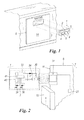
- an interface of the invention is indicated overall by 1 and comprises a display unit 2 and/or a display panel 3, for example comprising one or more pushbuttons and/or display elements (such as LEDs or the like) 4.
- This interface comprises a casing 5 to be coupled (fixed or removable) by usual means (for example magnetic, glue or mechanical such as clips, screws or the like) to a housing 6 of a household electrical appliance 7.
- This latter comprises at least one internal cavity 10, open at 27 on a side 11 at which a door 12 is present (to tightly close the cavity 10) and presents usual members 13 (for example a compressor of a refrigeration circuit in Figure 4 ) for its normal operation.
- the door 12 is panelled, i.e. is faced with a panel 14 formed such as to be able to inset the appliance into a modular unit 16 of a kitchen 17, said panel 14 having the same features as the panels or facings of this latter.
- the interface 1 is positioned on said panel 14 (or on a panel of one of the parts of the appliance if these are more than one); alternatively, it can be coupled directly to the appliance door 12.
- the interface 1 is connected without wires to an appliance control unit 21, such that it is possible at least to display, on the display unit 2 or on the panel 3, information relative to the appliance operation.
- This information together with the energy for its operation, are transmitted to the interface without any connection cables physically connecting the control unit 21, which senses said information at the interface.
- connection between this latter and said unit 21 is achieved by low power consumption radio waves (ISM or 2.4 GHz) or, preferably, by utilizing resonant electromagnetic coupling technology; this avoids the use of other data collection and transfer methods which require much more energy, such as bluetooth connections.
- the remote connection protocol (for example via radiofrequency) is hence aimed at energy saving and does not include the facility for continuous video-audio reproduction.
- the interface 1 can simply be a member displaying data (for example the refrigerator internal temperature or the time remaining to the end of wash) by its own display unit.
- the interface 1 if provided with data entry devices such as keys, can also send (and not only receive) data to the unit 21 to control the electrical appliance operation without opening its door 20.
- the interface 1 comprises an electromagnetically resonant circuit 30 (or via radio) coupled to another oscillating circuit 31 associated with the interior of the appliance housing 12, which is forced into oscillation.
- This circuit 31, which can also be positioned on a wall defining the appliance internal cavity 10 in proximity to the aperture 27 in the housing side 11, is connected to the control unit 21 for the appliance operation so as to receive therefrom the information to be transmitted, remotely or without wires, to the interface 1, together with the energy required for its operation.
- the oscillating signal which transports the operating energy for the interface 1, is modulated with the information to be transmitted thereto, by the modulation circuit 44 described hereinafter.
- the interface 1, if suitably formed, can also transfer other data or commands to the unit 21 such as to modify the appliance operation in the desired manner.
- the remote electromagnetic coupling between the resonant circuit 30 of the interface 1 and the oscillating circuit 31 need not necessarily be optimised, in the sense that the two circuits need not necessarily oscillate and resonate at the same frequency.
- a stage of synchronization of the oscillation and resonance frequencies of the two circuits 30 and 31 can however still be provided. This synchronization further optimises transfer of energy between the two circuits and of the signal superposed on it.
- the resonant circuit 30 of the interface 1 is located within an electric circuit 33 comprising a high charge capacity capacitor 34 (supercapacitor) able to accumulate energy and enable correct operation of the interface 1. This energy is therefore received by the electromagnetic or radio connection with the circuit 31, so that the interface 1 does not require a battery.
- a battery can be provided for partial operation of the interface or photovoltaic cells can be provided for charging the supercapacitor, said cells being disposed in a suitable position on the casing 5 of the interface 1.
- these photovoltaic cells can directly power the electric circuit 33 of the interface 1.
- the circuit 33 also comprises a further demodulator circuit 41 to control the display unit 2 or the panel 3; in particular, this demodulator 41 powers the LEDs 39 of this latter.
- the display circuit can also include a liquid crystal display (LCD).
- LCD liquid crystal display
- the interface 1 comprises the demodulator 41 connected to an antenna 42 (or magnetic field generator), formed by the resonant circuit 30, as in the case of the electromagnetic coupling.
- a signal superposed on the powering energy can be decoded in order to selectively activate the output elements (LEDs or LCD elements), and possibly enable data entry elements (keys) of the user interface 1.
- Another antenna 43 (or magnetic field generator) is associated with the circuit 31 comprising (again in its simplest form) the aforesaid modulator 44, to modulate the oscillating signal with the signal to be transferred to the interface 1.
- the demodulator 41 becomes a modulator/demodulator as does the modulator 44.
- this latter can be easily mounted by the user without any need of intervention by a specialized operator.
- the only care required is to associate the interface 1 with the door in a suitable position such that it faces the circuit 31 present in the appliance housing 6. In this manner, energy and signals can be transferred via a usual appliance cover panel of good appearance.
- a variation of the amplitude of the signal in the oscillating circuit 31 can be used to detect when the door of the appliance is open or closed.
- metallic mass for instance the door itself or a metallic plaque associated with a non metallic door
- it causes relevant amplitude variations of the signal on the coil 43 (the antenna), enabling to the control 21 to discriminate between the two door positions.
- the interface 1 can be used to interact, without wires, with a plurality of household electrical appliances selected from a menu or list. To simplify this selection, the user can choose to select the appliance with which to communicate only by moving the interface 1 close to the appliance. In this case the interface is activated to "dialogue" with the closest appliance on the basis of the force of the remote signal (RSSI).
- RSSI remote signal
- a household electrical appliance already purchased by a user and arranged for this functionality can also be associated with an interface 1.
- a radio-transmitter module has to be applied to the usual appliance control unit to enable "dialogue” with the interface 1 and hence form an electrical appliance "network”.
- the method of forming said network and the manner in which a new electrical appliance is inserted into the network are shown in Figure 5 .
- block 50 checks whether information indicating the presence of an electrical appliance has been received; if positive, block 51 checks whether the information originates from an appliance already in the network. If this is the case, the data received are processed (block 52), whereas in the opposite case, block 53 checks whether the force of the radio signal is such as to enable the electrical appliance to be inserted into the network. If the response is positive (block 54), the new electrical appliance is inserted into the network; in the opposite case (block 55), the data reading is discarded.
- the first appliance 100 is used (and commanded) as a signal repeater, and the information to the second appliance 102 is fed by the first appliance 100.
- the various appliances can be differently synchronized via the interface 1, so that their data do not become superposed, it being also possible to choose a main appliance within the network with which all the network appliances are synchronized. If this main appliance or leader is deactivated, the second network appliance chosen as the appliance immediately following the main appliance intervenes.
- synchronization of the various appliances can also be achieved by providing an internal clock individual to each of them; if an appliance has an external clock receiver (or if its own clock receives the time from a remote time provider, such as an atomic clock or via the internet), it can share information on its operation or its synchronization with all the other electrical appliances connected to the network. Appropriate food information can also be shared between several appliances of the network for the purpose of food preparation and storage.
- the leader appliance is preferably that presenting the highest precision of its own internal clock, and associating in this sense a quality index with the clocks associated with the individual appliances of the network.
- the indication of the clock quality factor together with the actual value of the clock is inserted into the information communication string towards the other network appliances, to enable the main appliance to be defined.
- the transmission of this communication can be periodically and automatically repeated, so avoiding the user having to carry out manual clock synchronization operations.
- appliance operation for example the foods contained in the refrigerator
- information on appliance operation can be shared, for the purpose of their preparation and storage, by several network appliances.
- the interface 1 is operate without a battery, it is of low construction cost and reduced environmental impact.
Landscapes
- Engineering & Computer Science (AREA)
- Textile Engineering (AREA)
- Chemical & Material Sciences (AREA)
- Combustion & Propulsion (AREA)
- Mechanical Engineering (AREA)
- General Engineering & Computer Science (AREA)
- Selective Calling Equipment (AREA)
- Electric Stoves And Ranges (AREA)
- User Interface Of Digital Computer (AREA)
Applications Claiming Priority (1)
| Application Number | Priority Date | Filing Date | Title |
|---|---|---|---|
| IT002129A ITMI20072129A1 (it) | 2007-11-07 | 2007-11-07 | Interfaccia utente per il comando di un elettrodomestico collegata a distanza a quest'ultimo |
Publications (2)
| Publication Number | Publication Date |
|---|---|
| EP2058595A2 true EP2058595A2 (fr) | 2009-05-13 |
| EP2058595A3 EP2058595A3 (fr) | 2017-03-15 |
Family
ID=40303662
Family Applications (1)
| Application Number | Title | Priority Date | Filing Date |
|---|---|---|---|
| EP08168154.6A Withdrawn EP2058595A3 (fr) | 2007-11-07 | 2008-11-03 | Interface utilisateur pour la commande d'un appareil électrique domestique connecté à distance |
Country Status (4)
| Country | Link |
|---|---|
| US (1) | US8606180B2 (fr) |
| EP (1) | EP2058595A3 (fr) |
| BR (1) | BRPI0804922A2 (fr) |
| IT (1) | ITMI20072129A1 (fr) |
Cited By (9)
| Publication number | Priority date | Publication date | Assignee | Title |
|---|---|---|---|---|
| EP2260751A1 (fr) * | 2009-06-10 | 2010-12-15 | Electrolux Home Products Corporation N.V. | Appareil domestique |
| WO2012047904A3 (fr) * | 2010-10-05 | 2013-07-04 | Illinois Tool Works Inc. | Console d'appareil ayant une fixation sans connecteur à l'appareil |
| DE102014201926A1 (de) * | 2014-02-04 | 2015-08-06 | BSH Hausgeräte GmbH | Haushaltsgerät |
| CN107248462A (zh) * | 2017-08-07 | 2017-10-13 | 浙江好易点智能科技有限公司 | 一种无需电池的多键晾衣机的遥控器 |
| DE102017004607A1 (de) | 2017-01-24 | 2018-07-26 | Liebherr-Hausgeräte Ochsenhausen GmbH | Kühl- und/oder Gefriergerät |
| EP3838102A1 (fr) * | 2019-12-19 | 2021-06-23 | Miele & Cie. KG | Appareil électroménager |
| CN113377038A (zh) * | 2020-03-10 | 2021-09-10 | Bsh家用电器有限公司 | 用于不同类型的家用器具的操作部分 |
| EP4173542A1 (fr) * | 2021-10-27 | 2023-05-03 | Miele & Cie. KG | Réfrigérateur avec un transfert d'énergie sans fil à travers un front de cuisine |
| WO2024013344A1 (fr) * | 2022-07-13 | 2024-01-18 | Everever | Structure de façade avant pour porte frontale de lave-vaisselle |
Families Citing this family (25)
| Publication number | Priority date | Publication date | Assignee | Title |
|---|---|---|---|---|
| DE102009002774A1 (de) * | 2009-04-30 | 2010-11-04 | BSH Bosch und Siemens Hausgeräte GmbH | Verfahren zum Betreiben eines Haushaltsgeräts, portable Bedieneinheit und Haushaltsgerät |
| EP2392859B1 (fr) * | 2010-05-05 | 2017-03-29 | Electrolux Home Products Corporation N.V. | Interface de table de cuisson, panneau de table de cuisson, dispositif de cuisson et procédé de fonctionnement d'une interface de table de cuisson |
| EP2575084A1 (fr) * | 2011-09-30 | 2013-04-03 | Nxp B.V. | Jeton de sécurité et système d'authentification |
| US9687134B2 (en) | 2011-11-23 | 2017-06-27 | Whirlpool Corporation | Dishwasher with transforming door |
| US10004379B2 (en) | 2011-11-23 | 2018-06-26 | Whirlpool Corporation | Dishwasher with transforming door |
| DE102011088918A1 (de) * | 2011-12-16 | 2013-06-20 | E.G.O. Elektro-Gerätebau GmbH | Verfahren zum Übertragen von Daten, Induktionsheizvorrichtung, induktiv beheizbares Kochgefäß und System |
| US9173542B2 (en) * | 2012-09-05 | 2015-11-03 | Whirlpool Corporation | Dishwasher with offset open face |
| US9375125B2 (en) | 2012-12-20 | 2016-06-28 | Whirlpool Corporation | Household appliance having antennas |
| US9572475B2 (en) | 2013-04-29 | 2017-02-21 | Whirlpool Corporation | Appliance with closure element having an operative device |
| DE102013223934A1 (de) * | 2013-11-22 | 2015-05-28 | BSH Hausgeräte GmbH | Haushaltsgerät |
| US10962233B2 (en) * | 2014-04-07 | 2021-03-30 | Elicas.P.A. | Domestic hoods |
| US10148495B1 (en) * | 2014-06-09 | 2018-12-04 | Amazon Technologies, Inc. | Remote configuration of wireless devices |
| DE102014112310A1 (de) | 2014-08-27 | 2016-03-03 | Vorwerk & Co. Interholding Gmbh | System aus einem elektrischen Küchengerät und einem Zusatzmodul |
| DE102014113273A1 (de) * | 2014-09-15 | 2016-03-17 | Vorwerk & Co. Interholding Gmbh | System aus einem elektrischen Küchengerät und einem Zusatzmodul |
| US9924849B2 (en) | 2014-10-07 | 2018-03-27 | Whirlpool Corporation | Dishwasher with integrated closure element having an antenna |
| US20160213187A1 (en) * | 2015-01-27 | 2016-07-28 | General Electric Company | Method for operating an appliance in a sabbath operating mode |
| US9528696B2 (en) * | 2015-05-12 | 2016-12-27 | Haier U.S. Appliance Solutions, Inc. | Appliance with dead front user interface |
| US10908762B2 (en) | 2015-07-20 | 2021-02-02 | Whirlpool Corporation | Household appliance closure element with touch interface |
| CN105005251A (zh) * | 2015-08-26 | 2015-10-28 | 芜湖松海信息科技有限公司 | 机柜远程维护系统 |
| US11018888B2 (en) * | 2015-12-03 | 2021-05-25 | Whirlpool Corporation | Methods of remote control of appliances |
| KR101864026B1 (ko) * | 2016-08-31 | 2018-06-01 | 엘지전자 주식회사 | 조리기기 및 조리기기의 제어방법 |
| US11193229B2 (en) | 2018-10-19 | 2021-12-07 | Whirlpool Corporation | User interface solutions for accessing appliance control through cosmetic outer cabinet |
| US12108907B2 (en) * | 2019-01-24 | 2024-10-08 | Breville Pty Limited | User interface for a cooking appliance |
| DE102019219802A1 (de) * | 2019-12-17 | 2021-06-17 | BSH Hausgeräte GmbH | Hausgerät mit austauschbarem Bedien- und/oder Steuerteil |
| US12522965B2 (en) | 2024-04-12 | 2026-01-13 | Haier Us Appliance Solutions, Inc. | Laundry assembly and dispenser drawer remote user interface |
Family Cites Families (22)
| Publication number | Priority date | Publication date | Assignee | Title |
|---|---|---|---|---|
| DE3412570A1 (de) * | 1984-04-04 | 1985-10-24 | Licentia Patent-Verwaltungs-Gmbh, 6000 Frankfurt | Vorrichtung zur elektrischen signalgabe bei offener tuer eines moebels |
| DE19615357A1 (de) * | 1995-05-11 | 1996-11-21 | Miele & Cie | Programmgesteuertes Haushaltgerät mit einer Anzeigevorrichtung |
| DE19615840A1 (de) * | 1996-04-20 | 1997-10-30 | Bosch Gmbh Robert | Elektrisches Hausgerät |
| US5847447A (en) * | 1996-07-09 | 1998-12-08 | Ambient Corporation | Capcitively coupled bi-directional data and power transmission system |
| DE19713686A1 (de) * | 1997-04-03 | 1998-10-08 | Frank Dipl Ing Arbeiter | Meldeeinrichtung für elektrisch betriebene Haushaltsgeräte |
| DE19959224B4 (de) * | 1999-12-08 | 2010-07-01 | E.G.O. Elektro-Gerätebau GmbH | System bestehend aus einem Elektrokochgerät und einer davon gesonderten Bedieneinheit |
| WO2001042865A1 (fr) * | 1999-12-10 | 2001-06-14 | Gentech Investment Group Ag. | Interface homme-machine |
| JP3921036B2 (ja) * | 2000-06-15 | 2007-05-30 | シャープ株式会社 | 電子レンジシステムおよび電子レンジ |
| KR100359827B1 (ko) * | 2000-11-27 | 2002-11-07 | 엘지전자 주식회사 | 홈 어플라이언스 네트워크 장치 및 방법 |
| DE10103302A1 (de) * | 2001-01-25 | 2002-08-01 | Bsh Bosch Siemens Hausgeraete | Elektrisches Haushaltsgerät mit Kommunikationsschnittstelle |
| US7216944B2 (en) * | 2001-08-15 | 2007-05-15 | General Electric Company | Dishwasher door assembly |
| US7133739B2 (en) * | 2001-11-01 | 2006-11-07 | Salton, Inc. | Intelligent microwave oven |
| ITMI20020053A1 (it) * | 2002-01-14 | 2003-07-14 | Whirlpool Co | Dispositivo di comando di un elettrodomestico di semplice realizzazione |
| JP2003319573A (ja) | 2002-04-23 | 2003-11-07 | Sharp Corp | 電力伝達装置、信号伝達装置、これらを用いた冷蔵庫 |
| ES2262906T3 (es) * | 2003-01-21 | 2006-12-01 | Whirlpool Corporation | Frigorifico con compartimento interno divisible en zonas de temperatura independiente. |
| DE102004011453B4 (de) * | 2003-03-10 | 2018-07-19 | Lg Electronics Inc. | Netzwerksystem eines Kühlschranks sowie Verfahren zum Betreiben desselben |
| DE10339410A1 (de) * | 2003-08-27 | 2005-05-12 | Schott Ag | Schaltungsanordnung für ein Elektrogerät |
| US8005780B2 (en) * | 2005-06-09 | 2011-08-23 | Whirlpool Corporation | Taxonomy engine and dataset for operating an appliance |
| US7504951B2 (en) * | 2005-12-22 | 2009-03-17 | Xerox Corporation | Interface antenna |
| DE202006016113U1 (de) * | 2006-10-20 | 2007-04-12 | Bsh Bosch Siemens Hausgeraete | Bedienteil |
| US7625246B2 (en) * | 2007-01-04 | 2009-12-01 | Whirlpool Corporation | System for supplying service from an appliance to multiple consumer electronic devices |
| ITTO20070051A1 (it) * | 2007-01-24 | 2008-07-25 | Indesit Co Spa | Utenza elettrica, in particolare un elettrodomestico, relativo dispositivo ausiliario opzionale e sistema comprendente tali utenza e dispositivo |
-
2007
- 2007-11-07 IT IT002129A patent/ITMI20072129A1/it unknown
-
2008
- 2008-11-03 EP EP08168154.6A patent/EP2058595A3/fr not_active Withdrawn
- 2008-11-07 BR BRPI0804922-0A patent/BRPI0804922A2/pt not_active IP Right Cessation
- 2008-11-07 US US12/266,644 patent/US8606180B2/en active Active
Non-Patent Citations (1)
| Title |
|---|
| None * |
Cited By (11)
| Publication number | Priority date | Publication date | Assignee | Title |
|---|---|---|---|---|
| EP2260751A1 (fr) * | 2009-06-10 | 2010-12-15 | Electrolux Home Products Corporation N.V. | Appareil domestique |
| WO2012047904A3 (fr) * | 2010-10-05 | 2013-07-04 | Illinois Tool Works Inc. | Console d'appareil ayant une fixation sans connecteur à l'appareil |
| DE102014201926A1 (de) * | 2014-02-04 | 2015-08-06 | BSH Hausgeräte GmbH | Haushaltsgerät |
| DE102014201926B4 (de) | 2014-02-04 | 2020-07-09 | BSH Hausgeräte GmbH | Haushaltsgerät |
| DE102017004607A1 (de) | 2017-01-24 | 2018-07-26 | Liebherr-Hausgeräte Ochsenhausen GmbH | Kühl- und/oder Gefriergerät |
| CN107248462A (zh) * | 2017-08-07 | 2017-10-13 | 浙江好易点智能科技有限公司 | 一种无需电池的多键晾衣机的遥控器 |
| EP3838102A1 (fr) * | 2019-12-19 | 2021-06-23 | Miele & Cie. KG | Appareil électroménager |
| CN113377038A (zh) * | 2020-03-10 | 2021-09-10 | Bsh家用电器有限公司 | 用于不同类型的家用器具的操作部分 |
| EP4173542A1 (fr) * | 2021-10-27 | 2023-05-03 | Miele & Cie. KG | Réfrigérateur avec un transfert d'énergie sans fil à travers un front de cuisine |
| WO2024013344A1 (fr) * | 2022-07-13 | 2024-01-18 | Everever | Structure de façade avant pour porte frontale de lave-vaisselle |
| FR3137824A1 (fr) * | 2022-07-13 | 2024-01-19 | Everever | Structure de façade avant pour porte frontale de lave-vaisselle |
Also Published As
| Publication number | Publication date |
|---|---|
| US20090118848A1 (en) | 2009-05-07 |
| US8606180B2 (en) | 2013-12-10 |
| EP2058595A3 (fr) | 2017-03-15 |
| BRPI0804922A2 (pt) | 2010-07-27 |
| ITMI20072129A1 (it) | 2009-05-08 |
Similar Documents
| Publication | Publication Date | Title |
|---|---|---|
| US8606180B2 (en) | User interface for controlling a household electrical appliance remotely connected thereto | |
| EP1095440B1 (fr) | Systeme et procede de suivi d'une pluralite d'ustensiles electriques, notamment d'appareils electromenagers | |
| US9464813B2 (en) | Cooking device | |
| US8291816B2 (en) | Drawer type cooking device | |
| EP2385309B1 (fr) | Dispositif de cuisson | |
| US6409517B2 (en) | Device for electrically powering present on a part of household electrical appliance which is moveable relative to the main structure of this latter | |
| US20080105248A1 (en) | Cooking device | |
| WO2019137189A1 (fr) | Système d'alimentation électrique sans fil appliqué à un dispositif de réfrigération, ensemble de tiroirs, et dispositif de réfrigération associé | |
| US20110187574A1 (en) | Remote controlled power consuming device and module | |
| CN111752332B (zh) | 输入装置和家用电器 | |
| JP2005260891A (ja) | 家電機器 | |
| US20130190929A1 (en) | Appliance console with connector-free attachment to appliance | |
| CN218355820U (zh) | 烹饪电器 | |
| CN206037158U (zh) | 嵌入式微波烹饪器具 | |
| JP2009293845A (ja) | 引出し型加熱調理器 | |
| KR102702238B1 (ko) | 냉장고 | |
| CN106287857B (zh) | 嵌入式微波烹饪器具 | |
| US20030209544A1 (en) | Microwave oven and method of manufacturing the same | |
| KR102080514B1 (ko) | 이동 단말기, 홈 어플라이언스 및 그 동작방법 | |
| CN222395494U (zh) | 显示屏的无线供电装置及烹饪设备 | |
| CN216720272U (zh) | 开关面板 | |
| CN116018490B (zh) | 可移动式物品贮藏装置和家电烹饪系统 | |
| CN220344176U (zh) | 一种嵌入式多功能厨用烹饪器具 | |
| CN220707813U (zh) | 冷柜 | |
| KR20070005429A (ko) | 분리형 전자레인지 |
Legal Events
| Date | Code | Title | Description |
|---|---|---|---|
| PUAI | Public reference made under article 153(3) epc to a published international application that has entered the european phase |
Free format text: ORIGINAL CODE: 0009012 |
|
| AK | Designated contracting states |
Kind code of ref document: A2 Designated state(s): AT BE BG CH CY CZ DE DK EE ES FI FR GB GR HR HU IE IS IT LI LT LU LV MC MT NL NO PL PT RO SE SI SK TR |
|
| AX | Request for extension of the european patent |
Extension state: AL BA MK RS |
|
| PUAL | Search report despatched |
Free format text: ORIGINAL CODE: 0009013 |
|
| AK | Designated contracting states |
Kind code of ref document: A3 Designated state(s): AT BE BG CH CY CZ DE DK EE ES FI FR GB GR HR HU IE IS IT LI LT LU LV MC MT NL NO PL PT RO SE SI SK TR |
|
| AX | Request for extension of the european patent |
Extension state: AL BA MK RS |
|
| RIC1 | Information provided on ipc code assigned before grant |
Ipc: A47L 15/42 20060101AFI20170203BHEP Ipc: D06F 39/00 20060101ALI20170203BHEP Ipc: F24C 7/08 20060101ALI20170203BHEP |
|
| STAA | Information on the status of an ep patent application or granted ep patent |
Free format text: STATUS: REQUEST FOR EXAMINATION WAS MADE |
|
| 17P | Request for examination filed |
Effective date: 20170915 |
|
| RBV | Designated contracting states (corrected) |
Designated state(s): AT BE BG CH CY CZ DE DK EE ES FI FR GB GR HR HU IE IS IT LI LT LU LV MC MT NL NO PL PT RO SE SI SK TR |
|
| AKX | Designation fees paid |
Designated state(s): DE FR GB IT PL |
|
| STAA | Information on the status of an ep patent application or granted ep patent |
Free format text: STATUS: EXAMINATION IS IN PROGRESS |
|
| 17Q | First examination report despatched |
Effective date: 20180524 |
|
| STAA | Information on the status of an ep patent application or granted ep patent |
Free format text: STATUS: THE APPLICATION IS DEEMED TO BE WITHDRAWN |
|
| 18D | Application deemed to be withdrawn |
Effective date: 20181204 |