EP2058638A2 - Capteur de mesure pour moyens de traction mobiles - Google Patents
Capteur de mesure pour moyens de traction mobiles Download PDFInfo
- Publication number
- EP2058638A2 EP2058638A2 EP20080450174 EP08450174A EP2058638A2 EP 2058638 A2 EP2058638 A2 EP 2058638A2 EP 20080450174 EP20080450174 EP 20080450174 EP 08450174 A EP08450174 A EP 08450174A EP 2058638 A2 EP2058638 A2 EP 2058638A2
- Authority
- EP
- European Patent Office
- Prior art keywords
- transmission element
- sensor
- rotation
- axis
- web
- Prior art date
- Legal status (The legal status is an assumption and is not a legal conclusion. Google has not performed a legal analysis and makes no representation as to the accuracy of the status listed.)
- Withdrawn
Links
- 230000005540 biological transmission Effects 0.000 claims abstract description 120
- 229910000639 Spring steel Inorganic materials 0.000 claims abstract description 5
- 230000009471 action Effects 0.000 claims description 4
- 230000000284 resting effect Effects 0.000 abstract description 4
- 210000002414 leg Anatomy 0.000 description 40
- 238000005259 measurement Methods 0.000 description 23
- 238000005452 bending Methods 0.000 description 22
- 238000012549 training Methods 0.000 description 11
- 238000000034 method Methods 0.000 description 10
- 230000000694 effects Effects 0.000 description 9
- 230000001939 inductive effect Effects 0.000 description 8
- 238000006073 displacement reaction Methods 0.000 description 7
- 230000005291 magnetic effect Effects 0.000 description 6
- 230000001133 acceleration Effects 0.000 description 5
- 238000005516 engineering process Methods 0.000 description 5
- 230000003287 optical effect Effects 0.000 description 5
- 230000009467 reduction Effects 0.000 description 5
- 230000002349 favourable effect Effects 0.000 description 4
- 230000015572 biosynthetic process Effects 0.000 description 3
- 230000008859 change Effects 0.000 description 3
- 230000006835 compression Effects 0.000 description 3
- 238000007906 compression Methods 0.000 description 3
- 238000013461 design Methods 0.000 description 3
- 238000001514 detection method Methods 0.000 description 3
- 230000010355 oscillation Effects 0.000 description 3
- 238000012546 transfer Methods 0.000 description 3
- 230000006978 adaptation Effects 0.000 description 2
- 238000006243 chemical reaction Methods 0.000 description 2
- 238000010276 construction Methods 0.000 description 2
- 238000005520 cutting process Methods 0.000 description 2
- 210000003414 extremity Anatomy 0.000 description 2
- 210000002436 femur neck Anatomy 0.000 description 2
- 230000004907 flux Effects 0.000 description 2
- 238000009434 installation Methods 0.000 description 2
- 239000000463 material Substances 0.000 description 2
- 238000000691 measurement method Methods 0.000 description 2
- 230000001953 sensory effect Effects 0.000 description 2
- 238000005476 soldering Methods 0.000 description 2
- 210000002023 somite Anatomy 0.000 description 2
- 230000003313 weakening effect Effects 0.000 description 2
- 238000003466 welding Methods 0.000 description 2
- 206010001497 Agitation Diseases 0.000 description 1
- 241001136792 Alle Species 0.000 description 1
- 206010041953 Staring Diseases 0.000 description 1
- 238000004458 analytical method Methods 0.000 description 1
- 230000037007 arousal Effects 0.000 description 1
- 210000000746 body region Anatomy 0.000 description 1
- 235000019577 caloric intake Nutrition 0.000 description 1
- 230000007547 defect Effects 0.000 description 1
- 230000005284 excitation Effects 0.000 description 1
- 230000005294 ferromagnetic effect Effects 0.000 description 1
- 238000004519 manufacturing process Methods 0.000 description 1
- 230000001404 mediated effect Effects 0.000 description 1
- 239000012528 membrane Substances 0.000 description 1
- 230000003534 oscillatory effect Effects 0.000 description 1
- 230000000737 periodic effect Effects 0.000 description 1
- 230000002093 peripheral effect Effects 0.000 description 1
- 238000000554 physical therapy Methods 0.000 description 1
- 229920000642 polymer Polymers 0.000 description 1
- 238000003825 pressing Methods 0.000 description 1
- 230000008569 process Effects 0.000 description 1
- 230000004044 response Effects 0.000 description 1
- 238000004088 simulation Methods 0.000 description 1
- 238000010561 standard procedure Methods 0.000 description 1
- 230000002123 temporal effect Effects 0.000 description 1
- 239000004753 textile Substances 0.000 description 1
- 210000000689 upper leg Anatomy 0.000 description 1
- 239000002918 waste heat Substances 0.000 description 1
Images




Classifications
-
- G—PHYSICS
- G01—MEASURING; TESTING
- G01L—MEASURING FORCE, STRESS, TORQUE, WORK, MECHANICAL POWER, MECHANICAL EFFICIENCY, OR FLUID PRESSURE
- G01L5/00—Apparatus for, or methods of, measuring force, work, mechanical power, or torque, specially adapted for specific purposes
- G01L5/04—Apparatus for, or methods of, measuring force, work, mechanical power, or torque, specially adapted for specific purposes for measuring tension in flexible members, e.g. ropes, cables, wires, threads, belts or bands
- G01L5/10—Apparatus for, or methods of, measuring force, work, mechanical power, or torque, specially adapted for specific purposes for measuring tension in flexible members, e.g. ropes, cables, wires, threads, belts or bands using electrical means
- G01L5/102—Apparatus for, or methods of, measuring force, work, mechanical power, or torque, specially adapted for specific purposes for measuring tension in flexible members, e.g. ropes, cables, wires, threads, belts or bands using electrical means using sensors located at a non-interrupted part of the flexible member
-
- G—PHYSICS
- G01—MEASURING; TESTING
- G01L—MEASURING FORCE, STRESS, TORQUE, WORK, MECHANICAL POWER, MECHANICAL EFFICIENCY, OR FLUID PRESSURE
- G01L5/00—Apparatus for, or methods of, measuring force, work, mechanical power, or torque, specially adapted for specific purposes
- G01L5/04—Apparatus for, or methods of, measuring force, work, mechanical power, or torque, specially adapted for specific purposes for measuring tension in flexible members, e.g. ropes, cables, wires, threads, belts or bands
- G01L5/10—Apparatus for, or methods of, measuring force, work, mechanical power, or torque, specially adapted for specific purposes for measuring tension in flexible members, e.g. ropes, cables, wires, threads, belts or bands using electrical means
- G01L5/106—Apparatus for, or methods of, measuring force, work, mechanical power, or torque, specially adapted for specific purposes for measuring tension in flexible members, e.g. ropes, cables, wires, threads, belts or bands using electrical means for measuring a reaction force applied on a cantilever beam
Definitions
- the invention relates to a transducer for circulating traction means for determining the transmitted torque, with a stationary with respect to the traction means support member and a transmission element, on which two pulleys are provided which touch in different directions extending Weritzabête, and a sensor with the transmission element cooperates.
- the invention also relates in particular to a measuring system for (wheel) ergometers.
- Such measuring systems have been known for years. In terms of physical-mechanical quantities, they generally record the cadence and training performance. Further details or setting values such as "driving speed”, "road gradient", calorie consumption u. ⁇ . should be presented by the manufacturer only as a guide and be understood by the user only as such.
- cycle ergometers consist of four functional units: crank system, flywheel, braking system and the setting, measuring and display unit (electric-electronic periphery).
- the measuring system is usually integrated in the brake system.
- the latter has the task to "destroy" the registered by means of a crank in the ergometer mechanical work, namely to convert into waste heat.
- the flywheel should compensate for the high cranking cycle high roundness of the crank torque partially.
- the cadence is generally detected by means of conventional magnetic or optical sensors, which usually provide only one pulse per crank revolution.
- the ergometer's electrical-electronic peripherals must be able to impose on the subject that mechanical quantity which, in conjunction with the current cadence, provides the preset power.
- power is the product of angular velocity (a cadence conversion parameter) and torque.
- the ergometer must thus "provide” such a braking torque in a type of control procedure for the pedaling frequency, which is possibly measured in each crank cycle, that the set power value results.
- the measured quantities (1), (3) and (4) are determined according to standard methods or based on such.
- the measurement target (2) can only be obtained inadequately in the prior art, since all known methods are associated with considerable disadvantages.
- This measuring method has been known for a long time. It is used, inter alia, to paper, textile or other webs during manufacturing or reeling operations under to keep defined tension. In these cases, rollers or other circular cylindrical body serve to deflect the webs, bands u. ä.
- the US 4,909,086 A is the closest prior art and discloses a transducer for determining the torque of a belt drive. It consists of two pulleys, which are connected to each other via an elongate connecting element and the opposite in the opposite direction running belt sections, deflect inward and enclose between them as it were.
- the connecting element with the deflection rollers is connected via a bending beam with a stationary platform, wherein the bending beam extends along the entire distance between the platform and connecting element.
- the bending beam is provided with two strain gauges, which absorb the deformation of the bending beam when the connecting element with the rollers are deflected by the belt.
- the big disadvantage of this design is that the measuring effect is very low and therefore of limited accuracy.
- the GB 2 312 193 A discloses a device with a roller mounted between the belts whose displacement by a changing tensile force Switch is operated, which puts a motor into operation to assist the cyclist during training.
- the US 3,992,932 A and the US 3,598,999 A each describe a belt drive, which is guided between two rollers and deflected by them.
- the relative tension of the individual belt sections can be determined by means of a transducer.
- this construction requires adequate guidance of the rollers, since otherwise the entire transducer can swirl around.
- the GB 2 193 936 A discloses, in the context of a bicycle belt drive, a force sensor which cooperates with the chain drive via a rotatably mounted lever to engage a motor in response thereto. The determination of the torque is not possible with this arrangement.
- the transfer takes place between the inside of the chain drive and a transducer via a preloaded rotating lever.
- the reading is passed to a control unit to activate an auxiliary engine.
- the DE 34 29 864 A1 relates to a device for the distance-free measurement of the thread tension on the running thread. It is therefore no circulating thread and no traction means. It is only the tensile force, but no torque can be measured.
- the force sensor used is a membrane fitted with strain gauges, on which a rotatably mounted lever acts, which has a roller resting against the thread ( Fig. 4, 6 ).
- the DE 90 14 326 U1 discloses a Riemengebtriebe among other things for sports medical equipment having a rotatably mounted roller carrier, at the two arms respectively a roll from the outside of the belt is applied ( Fig. 1, 2 ). It is taken in this device, no measured value, but only subjected to the bias of the belt of a self-regulation, which responds to a variable torque.
- the object of the invention is to solve the problems of the prior art and to provide a transducer which provides accurate and reproducible measured values of transmitted torque and is simple and robust in construction and installation.
- stationary axis of rotation By forming a stationary axis of rotation between the transmission element and the carrier part, the rotation of the transmission element or the force necessary to prevent such a twist force is clearly defined. Limiting the degrees of freedom to a single axis of rotation not only allows extremely accurate and reproducible measurement results.
- the carrier part itself is stationary, thus resting with respect to the rotating traction means, it thus represents the reference point of the arrangement according to the invention.
- the term stationary axis of rotation means that the axis of rotation during the entire pivoting operation of the transmission element remains in the same place, ie with respect to the stationary support part does not change its position.
- measurements are also taken at each Any point of the transmission element or from any fixed point possible.
- the stationary axis of rotation is arranged substantially at the height of the axis of symmetry of two extending in different directions Anlagenstoffabête and sit the stationary axis of rotation and the axes of rotation of the pulleys substantially at the corners of an isosceles triangle, the contour of the triangle substantially with the Symmetry axis coincides.
- the torque sensor according to the invention utilizes the fact that the crank torque is reflected in the difference in tension between the belt section tapering towards the crank pulley and the belt section running away from it.
- the difference between the two running in different directions traction means is purely mechanical. If you let both Umlenk technique act on one and the same rigid component, then the resulting moment of both forces, based on any lying on the axis of symmetry of the belt or chain drive component point, a measure of the difference in amount of deflection - and thus for the Belt force difference and ultimately the crank torque.
- the transmission element is mounted on the carrier part via a joint.
- the realization of the axis of rotation with a joint is a particularly simple and reliable way. Upon the action of a crank torque on the belt drive and thus different deflection forces on the roller carrier this would swing into such an angular position in which the force resulting from both Umlenk conductedn about the pivot - or joint point disappears.
- the transmission element is mounted on the carrier part via a flexible web, wherein the length of the web is less than a quarter to form the stationary axis of rotation in the middle of the web, preferably less than one fifth, more preferably less than one tenth of the height of the isosceles triangle.
- the use of a flexible web with dimensions according to the invention also ensures the formation of a stationary axis of rotation.
- the concentration of the deformation to a small area which is substantially smaller than the distance between the axis of rotation and the height at which the pulleys are located, ensures a defined and computationally easy to handle rotational movement of the transmission element about a stationary axis of rotation. Due to variations in the dimensions and the material quality, the measuring range can be changed. For this purpose, only the web would be replaced.
- the pivotability of the transmission element about a point of the belt drive axis of symmetry is not offered by a joint connection.
- the otherwise by a joint connection unlimited offered, basically only slightly necessary pivoting of the transmission element is ensured at the same place by a pronounced cross-sectional weakening of a bar-shaped portion.
- the thickness of the web is less than half, preferably less than one third of its length.
- a pivoting movement of the transmission element about the stationary axis of rotation is prevented by a force sensor which is rigidly connected to the stationary carrier part and which contacts the transmission element at a stop point.
- the pivoting is thus prevented by a supporting force, which acts by means of a force sensor on the transmission element.
- the reading of this sensor multiplied by the distance between Force sensor point of application and joint point yields the sought momentum about the stationary axis of rotation of the transmission element.
- the measuring axis of the force sensor is substantially normal to the connecting line between the axis of rotation and the stop point.
- the stationary axis of rotation coincides with the axis of a planetary gear for the circulating traction means.
- a distance sensor for determining the rotation of the transmission element is provided as a sensor.
- the distance sensor is in mechanical contact with the transmission element and preferably operates according to inductive, capacitive or potentiometric principle.
- the distance sensor is a non-contact, preferably optical or inductive, sensor.
- At least one strain sensor is provided on the flexible web for determining its curvature.
- the transmission element has a bar-shaped section which extends along the contour line of the triangle in the direction of the carrier part, and the bar is formed by a narrowing of the bar-shaped section.
- a web element preferably of spring steel, is provided at the end of the bar-shaped section as web.
- the latch-shaped portion has at its end a slot in which the sheet member is inserted.
- the sheet member is attached to an outer side of the end portion of the bar-shaped portion, e.g. bolted, riveted, welded or soldered.
- the blade element is detachably connected to the transmission element and the carrier part.
- the transmission element has a quadrangular shape, wherein in two corner regions in each case a deflection roller, in a further corner region the stationary axis of rotation and in the fourth corner region a reference point for the sensor, e.g. an attachment point for a force sensor or a measurement point for a distance sensor, is provided
- the transmission element has a triangular shape, wherein in each case a deflection roller is provided in two corner regions and the stationary rotation axis is provided in the third corner region, wherein at a further point, preferably on the outer contour of the transmission element, a reference point for the sensor, e.g. an attachment point for a force sensor or a measurement point for a distance sensor, is provided.
- Three legs can be added to a closed triangle contour with higher mechanical stability. If, on the third leg, a preferably parallel, outwardly facing, bar, e.g. arranged in the form of a console and located in the areas of the outer end of the force sensor, this allows a greater acting as a lever length distance between the measuring and articulation point, a small force acting on the sensor supporting force and thus the smallest dimensions for the sensor and its holder.
- a preferably parallel, outwardly facing, bar e.g. arranged in the form of a console and located in the areas of the outer end of the force sensor, this allows a greater acting as a lever length distance between the measuring and articulation point, a small force acting on the sensor supporting force and thus the smallest dimensions for the sensor and its holder.
- the transmission element is V-shaped, wherein at the two leg ends in each case a deflection roller and the cutting axis of both legs are provided, and wherein at a further point, preferably on the outer contour of the transmission element, a reference point for the Sensor, for example, a stop point for a force sensor or a measuring point for a distance sensor, is provided.
- V-shape transmission element of the force sensor does not attack directly on one of the legs, but at a projecting approximately parallel to the bisector in the interior of the V-contour rod-like bolt.
- the transmission element has a Y-contour.
- the transmission element has a triangular contour with a bar-shaped section running along the symmetry axis in the direction of the carrier part.
- a bolt is provided at the end opposite the stationary axis of rotation of the transmission element, which extends substantially parallel to the axis of symmetry and a reference point for the sensor, for example, a stop for a force sensor or a measuring point for a distance sensor carries.
- the pivotable about the stationary axis of rotation transmission element receives an elastic restoring action, preferably by a torsion spring centered about the axis of rotation or a normal to the connecting line between the axis of rotation and its point of application on the transmission element oriented linear spring.
- the object of the invention is also achieved with an ergometer or sports or training device, which is driven by rotating traction means, wherein it has a transducer of the type described above.
- the same calibration constant can be determined, which reflects the necessarily linear relationship between the crank torque and the sensor force or the measured distance change.
- the force sensor attack point on the transmission element is not least determined by the possibility of the force sensor as possible - and separately from the transmission element - to attach to the ergometer frame, be it directly or indirectly.
- the transmission element can be made, for example, all over the surface, preferably then its outer contour will rest on the force sensor.
- a locally reduced bending stiffness may instead of a local cross-sectional reduction be achieved on an otherwise continuous bolt also characterized in that this bolt is interrupted at a short distance and both opposing bolt ends are connected by a considerably narrower, web-like element.
- the latter may also consist of easily deformable material, and the high, but always elastic deformability of a spring leaf can be used for this web element.
- the connection of the web or leaf element with the adjacent bolt ends can be effected, for example, by inserting the former in slots of the latter.
- the web or leaf element can be screwed to the upper or lower outer contour of both bolt ends, welded, soldered or connected in a similar manner plan.
- the moment of force exerted on it by two deflection forces can also be measured by the pivoting of the roller carrier into an adjacent angular position not prevented by the supporting force of a force sensor but deliberately made possible and instead of the corresponding one Support force characteristic parameters of the pivoting movement can be used as a measure of the applied moment of force.
- the displacement of specific body points of the transmission element or the reduction of preferably lying on the symmetry axis points come into question.
- Displacement or Absenkdistanz example by touching, such as inductive or capacitive Abstandsaufsacrificing or non-touching, such as by optical methods, u. a. be measured by laser technology.
- variable which characterizes the transmission element pivoting movement is that variable which is the kinematic prerequisite for this - the curvature of the weakened locking neck or inserted web or leaf element.
- This curvature can be detected, for example, by means of strain gauge technology.
- the cooperating with the transmission element sensor is arranged on or in the transmission element.
- the sensor measures the deformation of the transmission element itself, such as bending, compression or elongation, or internal reactions (forces, moments, etc.) of the mechanical system formed by the transmission element and the sensor, which are caused by the traction means.
- the sensor can be designed as a tensile force sensor, bending moment sensor, transverse force sensor, etc., and is arranged directly on the transmission element or integrated therein.
- a pivoting movement of the roller carrier is neither completely obstructed - such as by a supporting applied force sensor - still allowed in only a small extent - such as by the elastic support effect of a bending web - but freely admitted.
- the transmission element will then pivot by a small pivot angle in such an angular position in which the rotational effects of both deflection forces cancel each other with respect to the transmission element axis of rotation. In this equilibrium position, each of the two approximately equally large deflection forces can be used as a measure of the acting crank torque.
- the transmission element consists of a along the axis of symmetry extending bar-like or flat-shaped middle part and two protruding arms or brackets, at the end of each a deflection roller is located.
- a traction sensor is inserted for measuring the deflecting force introduced by the adjacent roller.
- the tensile force sensor may represent the end region of the respective arm and be designed to support or support the deflection roller accordingly. In both cases, it is favorable if the measuring direction of the force sensor coincides as far as possible with the direction of the deflection force.
- the transfer element - without structuring in middle part and protruding arms - be flat, in a rough description in triangular form, wherein in a corner region the transmission element rotation axis, in a second a directly fixed deflection roller and in the third corner region the second, mounted by means of a force sensor deflection roller is located.
- the transmission element is essentially represented by two rod-shaped or bar-type legs joined together in V-shape, each having a deflection roller at the free leg ends and the transmission element rotation axis in the connection region of the two legs, then the two deflection forces tend to have this V Silhouette apart. Therefore, two characteristic for this type of load, effective within the leg cutting forces can be used as a measure of the deflection forces and thus for the crank torque: lateral force and bending moment.
- a transverse force sensor is inserted at any point of one of the two legs, in another, the free leg end is represented by a transverse force sensor, which is designed to receive a deflection roller. In both cases, it is favorable if leg longitudinal axis and deflecting force are oriented as normal as possible to one another.
- a bending moment sensor In order to measure the bending moment which is effective in the leg cross-section and proportional to its distance from the deflection roller, a bending moment sensor can be inserted into the limb interrupted at this point. Likewise, a limited, as far as possible from the deflection roller leg portion can be converted into a bending moment sensor. For example, by the limb in question is reduced to a limited length by cross-sectional weakening on a narrow, web-like neck, which undergoes a slight curvature upon application of the deflection force. The latter can be detected metrologically by means of strain sensors and used as a measure of the local bending moment, thus also for deflecting force and cranking moment.
- the web-like neck is not realized by local reduction of the original leg width, but by division of the leg, slotting the opposite leg ends parallel to the leg longitudinal axis and inserting a sheet element equipped by means of strain-sensor technology.
- this leaf element the two unslotted leg end portions connect in such a way that it is fitting, welded, soldered or glued to the outer contour of both leg end portions, with these.
- crankshaft torque transducers according to the invention are designed for use in belt drives.
- the designs are, however, without restrictions for - chainring and sprocket connecting - chain drives, or even for designs for circulating belts, ropes u. ä.
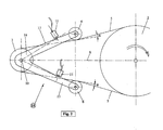
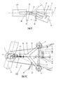
- the transducer 1 for the crank torque consists of a flat, substantially quadrangular, inserted between the pulley 2 and flywheel drive roller 3 roller carrier 4 for two - compared to the free belt sections 5 each inside - pulleys 6, which are located in two corner regions 7 of the transmission element 4.
- the latter is secured in the region of its third corner region 8 by means of a joint drive 10 situated on the belt drive symmetrical joint S on the ergometer frame, wherein the pivoting movement of the transmission element about the stationary axis of rotation 10 of the joint by a the transmission element in the region of fourth corner region 9 touchingly situated force sensor 11 is prevented.
- connection of joint 10 and force sensor 11 to the ergometer frame is not directly, but by means of a rigidly attached to the bearing holder 12 of the Ergometerrahmens bracket 13, which acts in the present example as resting in relation to the rotating traction means support member.
- joint 10 and force sensor 11 - seen from the line connecting the pulleys 6 - on the side of the flywheel drive roller 3.
- the joint 10 could be on the side of the crank axle or pulley 2 and - as well as force sensor 11 - to be attached there frame areas.
- the transmission element 18 in accordance with the invention Fig. 3 differs from the transfer element 16 in Fig. 2 essentially in that the force sensor 11 acts on a bolt-like bracket 19 projecting in the region of the bisecting line and approximately parallel to it in the V-contour.
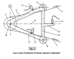
- the transmission element 21 according to the invention Fig. 4 goes from that according to Fig. 3 characterized in that the two connected to a V-shaped leg 17 are complemented by a substantially normal to the bisector oriented third leg 22 to a closed framework with the contour of an isosceles triangle and to support a force sensor 11 of the console 19 in Fig. 3 similar, bar-like and with the bisector approximately flush extending bracket to the leg 22 is rigidly connected.
- Abstützungsdorfkeit are in Fig. 4 entered two more force sensor positions.
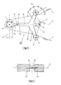
- Fig. 5 shows a transducer 25 according to the invention for the crank torque, in which the rotatability of the transmission element is not guaranteed by a joint connection to the ergometer frame, as a stationary support member, but by a based on local locking neck, web or leaf curvature hinge zone.
- Their function is illustrated by means of the transmission element 26, that of the transmission element 18 of Fig. 3 is similar, but he could also be those in Fig. 1 . 2 or 4 be similar to.
- the transmission element 26 (as well as 18) characterizing V-shaped legs 17 are continued in their lying on the axis of symmetry S connection area by a symmetry axis substantially parallel bar-shaped portion 27 which is either directly attached to the Ergometerrahmen or - Fig. 5 , similar to in Fig. 1 -
- a flat broadening 28 mounted on the bearing holder 14 for flywheel, brake system and drive roller 3, for example, is screwed.
- a portion of the bar-shaped portion 27 containing the axis of rotation 30 is shown.
- the hinge zone is not realized by local cross-sectional reduction of the bar-shaped portion 27, but by dividing it into two sections 31 a and 31 b and connecting the same by means of a narrow web or leaf element.
- the end faces of the locking portions 31a and 31b are slotted parallel to the axis of symmetry S and connected to each other by inserting a narrow blade member 32, such as spring steel.
- Fig. 7 is the blade member 32, at the upper outer contour of the two locking portions 31 a and 31 b fitting, in - these sections distancing manner - screwed. Likewise, a riveting, welding, soldering or other connection would be possible.
- Fig. 8 shows a transducer 34 according to the invention
- the transmission element 35 of the transmission element 21 of Fig. 4 is similar and directed to the axis of rotation 30
- bar-shaped portion 36 is connected by a blade member 32 to a rigidly connected to the ergometer frame component.
- this is a bracket 37, which in turn is rigidly secured to the bracket 14 for flywheel, brake system and the drive roller 3.
- Screw connections shown could - in particular between the latch-shaped portion 36 and the blade member 32 - also other types of connection such Riveting, soldering or welding occur, as could the blade member 32 integrated into the bar-shaped portion 36, so be made with this in one piece.
- the compared to the bar-shaped portion 36 extremely lower flexural rigidity of the blade member 32 ensures the same a hinge function, so when moment effect on the roller carrier 35 a pivoting movement of the same with the rotation axis 30 as a pole is possible - even if such by the Force sensor 11 is prevented.
- a transmission element pivoting movement mediated by hinge function of web or blade elements is kinematically identical to a rotational movement made possible by joint connection.
- the bending moment caused by the deflection force difference increases linearly along the latch-shaped section 27 and the blade element 32 up to the clamping point 39.
- the longitudinal axis of the sheet element curves to form a quadratic parabola 40 with a vertical axis and point 39 as a vertex - fractions of third order fall, since the longitudinal dimension a of the sheet element is significantly smaller than the horizontal distance of the sheet element relative to the deflection rollers, not significant.
- the axis 41 of the bolt 27 connects tangentially and rectilinearly in the parabola end point 42.
- the body point 43 approximately moves during a pivoting movement of the transmission element on a circular path with radius r about the axis of rotation 30.
- the above findings also apply without restriction to those embodiments in which the web or leaf foundation 32 is not in the longitudinal axis of a bar-shaped portion (about 27 ), but on its outer contour attached or otherwise attached to this. It is essential, however, that the symmetry axis of the web or leaf element runs in alignment with that of the belt drive. It should be stressed that in Fig. 9 the curvature of the web or leaf element 32 and the resulting rotational angle ⁇ of the transmission element or its bar-shaped portion 27 are shown greatly exaggerated.
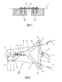
- the measuring transducer 45 in accordance with the invention Fig. 10 differs from the transducer 34 in Fig. 8 essentially by the absence of a supporting force sensor, as pivotal movement of the transmission member 35 about the axis of rotation 30 is intentionally permitted.
- the dimensioning of the blade element should - for predetermined values of crank torque, thus deflecting force difference and finally torque effect about the axis of rotation 30 - ensure that the blade element is claimed and deformed despite sufficient pivot angle exclusively in the elastic range.
- leaf elements made of spring steel allow higher tilt angle than they are metrologically necessary.
- the angle of rotation ⁇ could be measured and used as a measure of the causative crank torque. It is more favorable, however, to use the pivoting or displacement paths of characteristic points of the transmission element connected to the pivoting of the transmission element about the rotation axis 30. If it is a question of body points located on the belt drive symmetry axis-in the unloaded state-the use of the vertical lowering of such points is obvious.
- these reference points should lie on - with regard to the axis of rotation 30 - a large "radius", which is the case for example with the points 46 and 47 situated on the upper edge of the bolt 23, the latter in the form of a bracket ( Fig. 10 ).
- a measurement variant is also entered, in which the pivoting or displacement path of a transmission element point 50, which is not located on the belt drive symmetry axis in the initial state, is measured-for example by means of an optical sensor 49.
- the measuring range of the distance sensor used in each case can be utilized optimally for different areas of application of the ergometer and thus different crank torque limit values by incorporating or exchanging web or blade elements with different flexural rigidity, for example according to different blade thickness.
- Fig. 10 is the hinge area - similar to in Fig. 8 - Realized by a bolt-shaped portion 36 attached, screwed in the given case leaf element 32.
- the hinge function could by a web-like bolt neck 29 according to Fig. 5 or according to Fig. 6 be ensured by a in two separate, slotted bar ends 31 a and 31 b inserted sheet member 32.
- the displacement, such as lowering characteristic body points of the transmission element can also be used as a measure of the crank torque, if - as in Fig. 1 to 4 -
- the transmission element is rotatably supported by means of hinge 10 on the ergometer frame, but is provided by means of a spring element for an elastic restoring force on the transmission element. For this come both linear springs and a torsion springs in question.
- Fig. 11 to 13 Embodiment of the invention show in the areas of the axis of rotation 30, in which the rotational movement of the transmission element is not determined based on the displacement paths suitable body points, but by the This curvature is most easily obtained by measuring the associated strain on one and compression on the opposite contour surface of the web or leaf element. Strain and compression values can be measured either by glued piezoresistive strain gauges (DMS) or inductive strain gauges (inductive strain gauges) - both possible sensory elements are measured in Fig. 11 to 13 shown under item 52 or designated.
- DMS piezoresistive strain gauges
- inductive strain gauges inductive strain gauges
- Fig. 11 in this case represents a hinge zone equipped by means of strain sensors, which is characterized by an exchangeable blade element 32 inserted into two separate, slotted latch ends 31a and 31b, Fig. 12 a similarly adapted hinge zone for a fastened to the latch-shaped portion 36, screwed in the given case, at least exchangeable blade member 32, finally shows Fig. 13 an applied with strain sensor web-like bolt neck 29th
- Fig. 14 shows as a further variant of the invention, a transducer 54, the transmission element 55 in the joint 56 - for lack of any support against rigid frame areas - is freely rotatably mounted, its angular position can therefore play in the force of both belt sections 5 in such a way that the two pulleys 6 mutually cancel the rotational effects exerted on the transmission element 55 about the pivot point 56.
- the upper deflecting force U o serves as a measure of the acting crank moment (likewise, the lower deflecting force U u can be used).
- the transmission element 55 consists of a along the axis of symmetry S extending bar-like middle part 57, in which the flywheel roller 3 facing end portion 58, the hinge 56 is located and at the other end 59 two oriented to the belt sections 5 arms 60 are rigidly connected, in whose end portions 61, the guide rollers 6 are mounted.
- a tension force sensor 62 of arbitrary mode of operation is inserted for the purpose of measuring the deflection force U o , the measuring axis of which should point as far as possible in the direction of U o .
- Fig. 14 the component or region of the ergometer frame which acts as a carrier part and which receives the joint 56 is not shown. Furthermore, the transducer 54 is shown in its initial position and not in the slightly counterclockwise pivoted angular position due to the crank torque. This also applies to the Fig. 15 . 16 and 17 ,
- the in Fig. 15 shown transducer 64 differs from the transducer 54 according to Fig. 14 -
- the axis of rotation of the flywheel-roller also serves as a rotation axis 10 of the transmission element 65 - especially in that its transmission element 65 is flat and triangular in shape, with a corner region includes the axis of rotation 10, in the second a directly fixed guide pulley 6 and in the third corner region, a further deflection roller 6 is mounted by means of a correspondingly formed force sensor 66.
- Fig. 15 Measure the axis of the force sensor from the direction of the associated deflection force U o considerably, then their actually measured tensile component Z is suitable as a measure of the crank torque, but because of the also absorbed transverse component Q of the force sensor must be designed to be shear force-insensitive.
- Fig. 15 is indicated in dashed representation a possible recess of the otherwise full surface transmission element.
- the angled in V-contour transmission element 69 of the transducer 68 of Fig. 16 largely corresponds to the transmission element 16 of the pickup 15 according to Fig. 2 However, it has no stop for a force sensor, but is in one of the two legs 17 (according to Fig. 16 in the upper) a transverse force sensor 70 is inserted, which detects the parallel to its measuring axis and thus normal to the longitudinal leg axis transverse component Q of the deflection force U o . It is therefore favorable if leg longitudinal axis and deflecting force are oriented as normal as possible to each other.
- Fig. 17 shows a transducer 72 with also angled transmission element 73, in which the bending force exerted by the Umlenkkraft U o on the upper leg 74 bending effect in the greatest possible distance from the upper guide roller 6 by means of bending moment sensor - is detected - in principle any function.
- This sensor is in Fig. 17 similar to in Fig. 5 and 13 realized by a limited length realized by width reduction, equipped with strain sensor 52, web-like femoral neck 29 in already shown mode of action.
- a bridge-like femoral neck can also be described in a broad analogy to Fig. 6 by dividing the leg 74, slitting the two opposite leg end portions and inserting a sheet member 32 of small thickness can be realized.
- the blade element 32 can be inserted into both leg end regions in an always releasable manner and fixable by means of screws, so that the blade element is exchangeable for adaptation to different load levels.
- An embodiment according to Fig. 12 is also possible. In all of these embodiments, the sensor is seated on the blade element as part of the transmission element.
Landscapes
- Physics & Mathematics (AREA)
- General Physics & Mathematics (AREA)
- Chemical & Material Sciences (AREA)
- Analytical Chemistry (AREA)
- Force Measurement Appropriate To Specific Purposes (AREA)
Applications Claiming Priority (1)
| Application Number | Priority Date | Filing Date | Title |
|---|---|---|---|
| AT18042007A AT505034B1 (de) | 2007-11-08 | 2007-11-08 | Messwertaufnehmer für umlaufende zugmittel |
Publications (1)
| Publication Number | Publication Date |
|---|---|
| EP2058638A2 true EP2058638A2 (fr) | 2009-05-13 |
Family
ID=39830293
Family Applications (1)
| Application Number | Title | Priority Date | Filing Date |
|---|---|---|---|
| EP20080450174 Withdrawn EP2058638A2 (fr) | 2007-11-08 | 2008-11-06 | Capteur de mesure pour moyens de traction mobiles |
Country Status (2)
| Country | Link |
|---|---|
| EP (1) | EP2058638A2 (fr) |
| AT (1) | AT505034B1 (fr) |
Cited By (5)
| Publication number | Priority date | Publication date | Assignee | Title |
|---|---|---|---|---|
| CN107036752A (zh) * | 2017-05-05 | 2017-08-11 | 深圳市鑫华威机电设备有限公司 | 一种定子绕线机张紧度检测装置及其方法 |
| CN113029479A (zh) * | 2021-03-24 | 2021-06-25 | 上海电气风电集团股份有限公司 | 全尺寸叶片刚度检测方法、电子设备及存储介质 |
| CN113340523A (zh) * | 2021-04-16 | 2021-09-03 | 河南省计量科学研究院 | 一种触压式皮带张力计校准装置 |
| CN116296017A (zh) * | 2023-02-13 | 2023-06-23 | 莱顿汽车部件(苏州)有限公司 | 一种传动带拉力测量装置及测量方法 |
| CN121207401A (zh) * | 2025-11-21 | 2025-12-26 | 安徽希普泰科电子有限公司 | 具有多向负载功能的力学传感器 |
Families Citing this family (1)
| Publication number | Priority date | Publication date | Assignee | Title |
|---|---|---|---|---|
| DE102015211157A1 (de) * | 2015-06-17 | 2016-12-22 | Robert Bosch Gmbh | Verfahren zur Drehmomentbestimmung in einem Riementrieb |
Citations (9)
| Publication number | Priority date | Publication date | Assignee | Title |
|---|---|---|---|---|
| US3598999A (en) | 1969-02-17 | 1971-08-10 | Bendix Corp | Proportional trim control system for aircraft |
| US3992932A (en) | 1974-10-24 | 1976-11-23 | Borg-Warner Corporation | Torque measuring system |
| DE3429864A1 (de) | 1983-08-17 | 1985-05-09 | Barmag Barmer Maschinenfabrik Ag, 5630 Remscheid | Fadenzugkraftmessvorrichtung |
| GB2193936A (en) | 1986-08-14 | 1988-02-24 | Thomas North | Electrically assisted pedal vehicle |
| US4909086A (en) | 1987-11-17 | 1990-03-20 | Agency Of Industrial Science & Technology | Torque sensor of tension difference type for pulley-belt driving system |
| DE9014326U1 (de) | 1990-10-16 | 1990-12-20 | Keiper Dynavit GmbH & Co, 6750 Kaiserslautern | Riemengetriebe, insbesondere für Sportgeräte sowie sportmedizinische und medizinische Geräte |
| GB2312193A (en) | 1996-04-19 | 1997-10-22 | Russell John Searle | Auxiliary electric propulsion for a pedal-driven vehicle |
| CA2310974C (fr) | 2000-06-21 | 2002-02-05 | Thierry Routier | Bicyclette a derailleur; capteur mecanique retractable de tension de chaines pour controler un propulseur electrique |
| WO2004111591A1 (fr) | 2003-06-17 | 2004-12-23 | Spinpower B.V. | Systeme de transmission et procede de mesure de force d'entrainement |
Family Cites Families (2)
| Publication number | Priority date | Publication date | Assignee | Title |
|---|---|---|---|---|
| US4287759A (en) * | 1979-02-06 | 1981-09-08 | Fruehauf Corporation | Device for sensing the tension in a load carrying line |
| DE10016254B4 (de) * | 2000-04-03 | 2010-02-04 | Honigmann Industrielle Elektronik Gmbh | Zugkraftsensor |
-
2007
- 2007-11-08 AT AT18042007A patent/AT505034B1/de not_active IP Right Cessation
-
2008
- 2008-11-06 EP EP20080450174 patent/EP2058638A2/fr not_active Withdrawn
Patent Citations (9)
| Publication number | Priority date | Publication date | Assignee | Title |
|---|---|---|---|---|
| US3598999A (en) | 1969-02-17 | 1971-08-10 | Bendix Corp | Proportional trim control system for aircraft |
| US3992932A (en) | 1974-10-24 | 1976-11-23 | Borg-Warner Corporation | Torque measuring system |
| DE3429864A1 (de) | 1983-08-17 | 1985-05-09 | Barmag Barmer Maschinenfabrik Ag, 5630 Remscheid | Fadenzugkraftmessvorrichtung |
| GB2193936A (en) | 1986-08-14 | 1988-02-24 | Thomas North | Electrically assisted pedal vehicle |
| US4909086A (en) | 1987-11-17 | 1990-03-20 | Agency Of Industrial Science & Technology | Torque sensor of tension difference type for pulley-belt driving system |
| DE9014326U1 (de) | 1990-10-16 | 1990-12-20 | Keiper Dynavit GmbH & Co, 6750 Kaiserslautern | Riemengetriebe, insbesondere für Sportgeräte sowie sportmedizinische und medizinische Geräte |
| GB2312193A (en) | 1996-04-19 | 1997-10-22 | Russell John Searle | Auxiliary electric propulsion for a pedal-driven vehicle |
| CA2310974C (fr) | 2000-06-21 | 2002-02-05 | Thierry Routier | Bicyclette a derailleur; capteur mecanique retractable de tension de chaines pour controler un propulseur electrique |
| WO2004111591A1 (fr) | 2003-06-17 | 2004-12-23 | Spinpower B.V. | Systeme de transmission et procede de mesure de force d'entrainement |
Cited By (7)
| Publication number | Priority date | Publication date | Assignee | Title |
|---|---|---|---|---|
| CN107036752A (zh) * | 2017-05-05 | 2017-08-11 | 深圳市鑫华威机电设备有限公司 | 一种定子绕线机张紧度检测装置及其方法 |
| CN113029479A (zh) * | 2021-03-24 | 2021-06-25 | 上海电气风电集团股份有限公司 | 全尺寸叶片刚度检测方法、电子设备及存储介质 |
| CN113029479B (zh) * | 2021-03-24 | 2022-11-08 | 上海电气风电集团股份有限公司 | 全尺寸叶片刚度检测方法、电子设备及存储介质 |
| CN113340523A (zh) * | 2021-04-16 | 2021-09-03 | 河南省计量科学研究院 | 一种触压式皮带张力计校准装置 |
| CN113340523B (zh) * | 2021-04-16 | 2022-11-01 | 河南省计量科学研究院 | 一种触压式皮带张力计校准装置 |
| CN116296017A (zh) * | 2023-02-13 | 2023-06-23 | 莱顿汽车部件(苏州)有限公司 | 一种传动带拉力测量装置及测量方法 |
| CN121207401A (zh) * | 2025-11-21 | 2025-12-26 | 安徽希普泰科电子有限公司 | 具有多向负载功能的力学传感器 |
Also Published As
| Publication number | Publication date |
|---|---|
| AT505034B1 (de) | 2008-10-15 |
| AT505034A4 (de) | 2008-10-15 |
Similar Documents
| Publication | Publication Date | Title |
|---|---|---|
| DE102013014098B4 (de) | Pedalkraftmessvorrichtung | |
| AT505034B1 (de) | Messwertaufnehmer für umlaufende zugmittel | |
| DE102012104065B4 (de) | Fahrrad-Kraftmessanordnung | |
| DE4435174C2 (de) | Vorrichtung zur Erfassung der aufgebrachten Kräfte und Leistung an einer Kurbel | |
| DE2630228C3 (fr) | ||
| DE2524605A1 (de) | Vorrichtung zum messen von mechanischer arbeit und leistung | |
| EP2185250A1 (fr) | Procédé et dispositif de mesure des forces appliquées, du couple de rotation et du travail fourni sur un ergomètre ou une bicyclette | |
| DE102013007016A1 (de) | Fahrradkurbelarm | |
| EP1867891A1 (fr) | Procédé de détermination de chargement dans un lave-linge | |
| EP3590811A2 (fr) | Dispositif de mesure des puissances | |
| DE102012213698B4 (de) | Kraftmessachse mit orientierter Anbringung | |
| EP1326683A1 (fr) | Dispositif de determination de la force de pedalage | |
| DE102012214332A1 (de) | Leistungssensorik für Fahrräder | |
| DE19523756A1 (de) | Arbeitsmaschine und Sensor für eine Arbeitsmaschine | |
| WO2005021368A1 (fr) | Support de capteur | |
| EP3331340B1 (fr) | Attelage trois points | |
| CH652209A5 (de) | Kraftmesser. | |
| DE29803763U1 (de) | Arbeits- bzw. Leistungsmeßvorrichtung für Fahrzeuge mit Kettenantrieb sowie Vorrichtung zur Messung der über ein biegsames Element übertragenen Zugkraft | |
| EP3856625B1 (fr) | Transmission à manivelle comprenant un arbre de manivelle à relier à au moins une manivelle au pied ou manuelle | |
| DE10249804B4 (de) | Verfahren und Vorrichtung zur Leistungsbestimmung bei Ergometern | |
| DE102004017679B4 (de) | Trainingsgerät | |
| EP4396071A2 (fr) | Pédalier et véhicule | |
| DE19930406B4 (de) | Bewegungsgerät mit zwei Betätigungselementen für ein Extremitätenpaar einer Person | |
| DE4338819A1 (de) | Leistungsmesser | |
| DE102022103666B4 (de) | Sensorsystem zur Ermittlung einer Kraftausübung auf ein Pedal, Antriebseinheit, Sensoreinheit und Verfahren zur Einstellung einer Unterstützungsleistung einer Antriebseinheit |
Legal Events
| Date | Code | Title | Description |
|---|---|---|---|
| PUAI | Public reference made under article 153(3) epc to a published international application that has entered the european phase |
Free format text: ORIGINAL CODE: 0009012 |
|
| AK | Designated contracting states |
Kind code of ref document: A2 Designated state(s): AT BE BG CH CY CZ DE DK EE ES FI FR GB GR HR HU IE IS IT LI LT LU LV MC MT NL NO PL PT RO SE SI SK TR |
|
| AX | Request for extension of the european patent |
Extension state: AL BA MK RS |
|
| STAA | Information on the status of an ep patent application or granted ep patent |
Free format text: STATUS: THE APPLICATION IS DEEMED TO BE WITHDRAWN |
|
| 18D | Application deemed to be withdrawn |
Effective date: 20130601 |