EP2058641B1 - Isokinetische Sonde zur Analyse der Verschmutzung der Gase, die von einem Flugzeugmotor erzeugt werden - Google Patents
Isokinetische Sonde zur Analyse der Verschmutzung der Gase, die von einem Flugzeugmotor erzeugt werden Download PDFInfo
- Publication number
- EP2058641B1 EP2058641B1 EP08167593A EP08167593A EP2058641B1 EP 2058641 B1 EP2058641 B1 EP 2058641B1 EP 08167593 A EP08167593 A EP 08167593A EP 08167593 A EP08167593 A EP 08167593A EP 2058641 B1 EP2058641 B1 EP 2058641B1
- Authority
- EP
- European Patent Office
- Prior art keywords
- iso
- tube
- probe according
- base
- kinetic
- Prior art date
- Legal status (The legal status is an assumption and is not a legal conclusion. Google has not performed a legal analysis and makes no representation as to the accuracy of the status listed.)
- Active
Links
Images

Classifications
-
- G—PHYSICS
- G01—MEASURING; TESTING
- G01N—INVESTIGATING OR ANALYSING MATERIALS BY DETERMINING THEIR CHEMICAL OR PHYSICAL PROPERTIES
- G01N1/00—Sampling; Preparing specimens for investigation
- G01N1/02—Devices for withdrawing samples
- G01N1/22—Devices for withdrawing samples in the gaseous state
- G01N1/2247—Sampling from a flowing stream of gas
-
- G—PHYSICS
- G01—MEASURING; TESTING
- G01N—INVESTIGATING OR ANALYSING MATERIALS BY DETERMINING THEIR CHEMICAL OR PHYSICAL PROPERTIES
- G01N1/00—Sampling; Preparing specimens for investigation
- G01N1/02—Devices for withdrawing samples
- G01N1/22—Devices for withdrawing samples in the gaseous state
- G01N1/2273—Atmospheric sampling
-
- G—PHYSICS
- G01—MEASURING; TESTING
- G01N—INVESTIGATING OR ANALYSING MATERIALS BY DETERMINING THEIR CHEMICAL OR PHYSICAL PROPERTIES
- G01N1/00—Sampling; Preparing specimens for investigation
- G01N1/02—Devices for withdrawing samples
- G01N1/22—Devices for withdrawing samples in the gaseous state
- G01N1/2247—Sampling from a flowing stream of gas
- G01N2001/225—Sampling from a flowing stream of gas isokinetic, same flow rate for sample and bulk gas
Definitions
- the invention relates to an isokinetic probe, in particular for the analysis of the pollution of gases generated by an aircraft engine, comprising an air sampling tube having an upstream end introduced into a duct in which a gaseous vein circulates. , means for adjusting the inlet velocity of the gas stream being provided at a fattening of the sampling tube.
- the document FR-A-2 141 220 describes an iso-kinetic probe for the analysis of the pollution of gases generated by an aircraft engine. It comprises an air sampling tube having an upstream end introduced into a duct in which circulates a gas stream, means for adjusting the inlet velocity of the gas stream being provided at a mouth of the sampling tube.
- Measurement probes are already known for analyzing the pollution of gases generated by an aircraft engine. These probes are iso-kinetic. This means that the air flows at the same speed in the sampling end of the probe and in the air stream in which the sample is taken. Tips of three different diameters are provided, it being understood that the air inlet velocity in the nozzle increases when the diameter of the sampling hole decreases at iso-suction flow. Alternatively or additionally, the inlet adjustment of the sampling tube is obtained by a pumping system downstream of the probe.
- the suction speed is known with a high degree of inaccuracy.
- the tip change requires disassembly of the sampling tube.
- this disassembly is inconvenient and takes time.
- it is necessary to test the tightness of the probe connection on the test piping after reassembly.
- the object of the present invention is to remedy these drawbacks by proposing an iso-kinetic probe which is easy to disassemble and reassemble and in which the air suction speed can be known with good accuracy.
- the tube has a downstream end fixedly mounted on a base (fixing guaranteeing the seal), said base having an outer diameter mounted in an inner diameter of a passage sleeve, the inner diameter of the passage bushing being sufficiently large so that the upstream end of the tube is able to pass through the inside diameter of the passage sleeve, the probe further comprising a measuring chamber having an end connected to the base.
- the end of the sampling tube is bent.
- the base has a flared portion which engages in a corresponding flared portion of the passage sleeve.
- the flared portion of the base is held firmly in abutment on the flared portion of the passage bushing by means of a nut.
- the measuring chamber has an end terminated by a nozzle, said nozzle being held firmly in abutment on the flared portion of the base by means of the nut.
- the iso-kinetic probe of the invention comprises, provided in the measuring chamber, means for measuring the static pressure, the total pressure and the temperature.
- the means for measuring the total pressure is, for example, a pitot tube.
- the means for measuring the temperature is constituted, for example, by a thermocouple.
- the knowledge of the three parameters total pressure, static pressure and temperature makes it possible to calculate the flow rate.
- the value of the flow obtained makes it possible to obtain the speed of the gas for a geometry given in the measuring chamber.
- the knowledge of the velocity of the gas in the measuring chamber makes it possible, by flow conservation equations, to calculate the velocity of the gas upstream, that is to say at the mouth of the sampling tube.
- the iso-kinetic probe comprises several sampling tubes having bent ends of different diameters, these sampling tubes being each mounted on a base of common outer diameter, this diameter being sufficiently large so that the bent end of the tube of more large diameter is able to pass through the inner diameter of the passage sleeve.
- the rate of gas penetration into the sampling tube can be easily adjusted by changing the tube. This operation can be performed quickly because, as explained previously, the sampling tube can be removed easily and quickly from the outside.
- the iso-kinetic probe comprises a diaphragm for varying the passage section at the inlet of the end of the air sampling tube. Thanks to the presence of this diaphragm, which can be operated from the outside of the duct, the passage section offered to the gases can be continuously varied, and consequently the velocity of the gas at the mouth of the sampling tube.
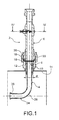
- the iso-kinetic probe of the invention consists of a sampling tube 4 and a measurement chamber 6.
- sampling tube 4 has a downstream end 8, a base 10 is integral.
- the base 10 is for example brazed or welded to the end 8 of the sampling tube.
- the base 10 has an outside diameter which is adjusted in the inner diameter of a passage bushing 12.
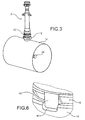
- the passage bushing 12 is itself fixed, for example welded or brazed, outside a conduit 14 of large diameter.
- the base 10 has a flared end, conical in the embodiment shown 16. This conical portion bears against a complementary conical portion 18 of the passage bushing 12.
- the lower end of the measuring chamber comprises a nozzle 20 which bears against the inner part of the conical portion 16.
- the nozzle 20 is itself held tight by a nut 22.
- the conical portion 16 is taken between the conical portion 18 of the passage sleeve 12 and the conical end of the nozzle 20.
- the sampling tube 4 has an upstream end 24 which has a mouth (26) and a bent portion 28.
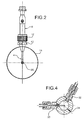
- the duct 14 has a circular section and the mouth 26 is located at the center of the circular section of the duct 14.
- the extraction of the sampling tube is carried out as follows. First of all, the nut 22 which has a threaded portion engaged with the passage bushing 12 is loosened and removed. The nut being unscrewed, the measuring chamber (6) is removed, which releases the base 10 It is then possible to withdrawing the sampling tube 4 as a whole by passing it through the passage bushing 12. It should be noted that, for this purpose, the inside diameter d of the bore provided in the passage sleeve is sufficiently large to allow the passage of the bent portion 28 of the tube and its mouth 26, which has a flared shape.
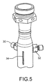
- measuring means comprise means for measuring the total pressure constituted by a Pitot tube 30, static pressure measuring means consisting of a static pressure sensor 32 and temperature measuring means.
- the knowledge of the total pressure, the static pressure and the temperature makes it possible to calculate the flow rate by the Bernouilli equations.
- the knowledge of the flow rate makes it possible to calculate the speed for a given geometry.
- the fact of knowing the speed of the fluid at the level of the measuring chamber makes it possible, by flow conservation equations, to know the speed upstream, that is to say at the mouth 26 of the sampling tube 4.
- angular orientation means In order to guarantee an angular orientation of the mouth 26 of the hole perfectly aligned with the longitudinal axis of the circular duct 14 is provided angular orientation means.
- these means consist of a groove 40 formed of the passage sleeve 12 and a lug 42 formed in the conical portion 16 of the base 10.
- the lug 42 When the lug 42 is inserted into the throat 40, it is ensured that the mouth 26 has the correct angular orientation with respect to the conduit 14. Furthermore, the lug 42 prevents the sampling tube from rotating relative to the passage sleeve 12. The lug 42 thus ensures at the same time an anti-rotation function.
- the larger diameter probe will be chosen for the low air velocities in the tube (in contrast, the smaller diameter will be chosen for the high air velocities in the tube ).
- the nut 22 is unscrewed, the measuring chamber 6 is removed. sampling 4a, 4b or 4c is then directly accessible.
- the outer diameter of the base 10a, 10b or 10c can slide freely in the inside diameter of the passage bushing 12. It will be observed that the inside diameter d of the passage bushing 12 is provided sufficiently large for the tube to be stronger. diameter, in this case the tube 4a, can pass into the bore provided in the passage sleeve.
Landscapes
- Health & Medical Sciences (AREA)
- Life Sciences & Earth Sciences (AREA)
- Engineering & Computer Science (AREA)
- Biomedical Technology (AREA)
- Molecular Biology (AREA)
- Physics & Mathematics (AREA)
- Chemical & Material Sciences (AREA)
- Analytical Chemistry (AREA)
- Biochemistry (AREA)
- General Health & Medical Sciences (AREA)
- General Physics & Mathematics (AREA)
- Immunology (AREA)
- Pathology (AREA)
- Sampling And Sample Adjustment (AREA)
Claims (11)
- Isokinetische Sonde, insbesondere zur Analyse der Verschmutzung der von einem Flugzeugmotor erzeugten Gase, mit einem Luftentnahmerohr, das ein stromaufwärts gelegenes Ende (24) aufweist, welches in einen Kanal (14) eingerührt ist, in dem eine Gasströmung zirkuliert, wobei Mittel zur Regelung der Eingangsgeschwindigkeit der Gasströmung an einer Mündung des Entnahmerohrs vorgesehen sind, dadurch gekennzeichnet, dass das Rohr (4) ein stromabwärts gelegenes Ende aufweist, das fest an einem Sockel (10) angebracht ist, wobei der Sockel (10) einen Außendurchmesser besitzt, der in einem Innendurchmesser d einer Durchgangshitlse (12) angebracht ist, wobei der Innendurchmesser der Durchgangshülse groß genug ist, damit das stromaufwärts gelegene Ende (24) des Rohrs (4) durch den Innendurchmesser der Durchgangshülse (12) laufen kann, wobei die Sonde ferner eine Messkammer (6) mit einem Ende aufweist, das an den Sockel angeschlossen ist.
- Isokinetische Sonde nach Anspruch 1, dadurch gekennzeichnet, dass das stromaufwärts gelegene Ende (24) des Entnahmerohrs gebogen ist.
- Isokinetische Sonde nach Anspruch 1 oder 2, dadurch gekennzeichnet, dass der Sockels (10) einen aufgeweiteten Teil (16) aufweist, der mit einem entsprechenden aufgeweiteten Teil (18) der Durchgangshülse (12) in Eingriff steht.
- Isokinetische Sonde nach Anspruch 3, dadurch gekennzeichnet, dass der ausgeweitete Teil des Sockels über eine Mutter (22) fest in Anlage an dem aufgeweiteten Teil (18) der Durchgangshül.se (12) gehalten wird.
- Isokinetische Sonde nach Anspruch 4, dadurch gekennzeichnet, dass die Messkammer ein Ende besitzt, welches durch einen Stutzen (20) abgeschlossen ist, wobei der Stutzen über die Mutter (22) fest in Anlage an dem aufgeweiteten Teil des Sockels gehalten wird.
- Isokinetische Sonde nach Anspruch 1, dadurch gekennzeichnet, dass sie in der Messkammer (6) vorgesehene Mittel (30, 32, 34) zum Messen des statischen Drucks, des Gesamtdrucks und der Temperatur aufweist.
- Isokinetische Sonde nach Anspruch 6, dadurch gekennzeichnet, dass das Mittel zum Messen des Gesamtdrucks ein Pitotrohr (30) ist.
- Isokinetische Sonde nach Anspruch 6 oder 7, dadurch gekennzeichnet, dass das Mittel zum Messen der Temperatur durch ein Thermoelement gebildet ist.
- Isokinetische Sonde nach einem der Ansprüche 1 oder 2, dadurch gekennzeichnet, dass sie mehrere Entnahmerohre (4a, 4b, 4c) mit stromaufwärts gelegenen Enden unterschiedlicher Durchmesser aufweist, wobei diese Entnahmerohre jeweils an einem Sockels mit gemeinsamem Außendurchmesser d angebracht sind, wobei dieser Durchmesser groß genug ist, damit das stromaufwärts gelegene Ende des Rohrs (4a) mit größerem Durchmesser durch den Innendurchmesser der Durchgangshülse (12) laufen kann.
- Isokinetische Sonde nach einem der Ansprüche 1 oder 2, dadurch gekennzeichnet, dass sie wenigstens eine an die Messkammer angeschlossene Pumpe aufweist, wobei die Pumpe erlaubt, die Ansauggeschwindigkeit der Gase an der Mündung des Entnahmerohrs (26) einzustellen.
- Isokinetische Sonde nach einem der Ansprüche 1 oder 2, dadurch gekennzeichnet, dass sie eine Membran aufweist, die ermöglicht, den Durchgangsquerschnitt am Eingang des Endes des Luftentnahmerohrs variieren zu lassen.
Applications Claiming Priority (1)
| Application Number | Priority Date | Filing Date | Title |
|---|---|---|---|
| FR0758751A FR2923014B1 (fr) | 2007-10-31 | 2007-10-31 | Sonde iso-cinetique pour l'analyse de la pollution des gaz generes par un moteur d'avion |
Publications (2)
| Publication Number | Publication Date |
|---|---|
| EP2058641A1 EP2058641A1 (de) | 2009-05-13 |
| EP2058641B1 true EP2058641B1 (de) | 2010-05-26 |
Family
ID=39516302
Family Applications (1)
| Application Number | Title | Priority Date | Filing Date |
|---|---|---|---|
| EP08167593A Active EP2058641B1 (de) | 2007-10-31 | 2008-10-27 | Isokinetische Sonde zur Analyse der Verschmutzung der Gase, die von einem Flugzeugmotor erzeugt werden |
Country Status (7)
| Country | Link |
|---|---|
| US (1) | US8171807B2 (de) |
| EP (1) | EP2058641B1 (de) |
| JP (1) | JP5188358B2 (de) |
| CA (1) | CA2642306C (de) |
| DE (1) | DE602008001352D1 (de) |
| FR (1) | FR2923014B1 (de) |
| RU (1) | RU2478927C2 (de) |
Families Citing this family (8)
| Publication number | Priority date | Publication date | Assignee | Title |
|---|---|---|---|---|
| EP2352982B1 (de) * | 2008-11-06 | 2015-09-30 | Stanislaw Kaminski | Verfahren und vorrichtung zur messung der staubkonzentration in gasströmen |
| US8234935B2 (en) * | 2010-10-28 | 2012-08-07 | Hamilton Sundstrand Corporation | Anti-rotation mechanism for pitot tube |
| US9473948B2 (en) | 2012-05-28 | 2016-10-18 | Huawei Technologies Co., Ltd. | Method and apparatus for analyzing pilot pollution |
| FR3012216B1 (fr) * | 2013-10-18 | 2017-04-21 | Snecma | Procede et dispositif de mesure de polluants contenus dans l'echappement d'un moteur |
| CN103913353B (zh) * | 2014-04-10 | 2016-04-13 | 北京大学 | 一种适用于机载测量的气体常压采样装置 |
| WO2015159193A1 (en) | 2014-04-14 | 2015-10-22 | National Research Council Of Canada | Air sensor with downstream facing ingress to prevent condensation |
| KR102002967B1 (ko) * | 2017-09-05 | 2019-10-01 | 주식회사 정엔지니어링 | 흡인노즐에 단면적 조절장치가 부착된 배기가스 연속 등속 채취 장치와 이를 결합한 배기가스 미세먼지 연속자동측정 시스템 |
| CN108548700B (zh) * | 2018-03-16 | 2019-07-23 | 华中科技大学 | 一种无水冷高温气溶胶定量稀释取样探头 |
Family Cites Families (21)
| Publication number | Priority date | Publication date | Assignee | Title |
|---|---|---|---|---|
| US3252323A (en) * | 1961-12-29 | 1966-05-24 | Litton Systems Inc | Particulate sampling device |
| US3395516A (en) * | 1964-01-31 | 1968-08-06 | Navy Usa | Airborne aerosol collector |
| US3707869A (en) * | 1971-06-09 | 1973-01-02 | Atomic Energy Commission | Airborne isokinetic sampler |
| US3793887A (en) * | 1972-12-05 | 1974-02-26 | Ford Motor Co | Isokinetic sampling probe |
| US3965748A (en) * | 1974-11-18 | 1976-06-29 | Rader Companies, Inc. | Apparatus for automatically measuring particulate emissions in gas flow |
| US4034611A (en) * | 1976-12-03 | 1977-07-12 | The United States Of America As Represented By The Secretary Of The Navy | Particulate sampling probe |
| US4276092A (en) * | 1979-12-03 | 1981-06-30 | Lafarge Consultants Ltd. | Manufacture of cement |
| JPH0375541A (ja) * | 1989-08-17 | 1991-03-29 | Mitsuo Samata | ダスト測定方法 |
| US4998954A (en) * | 1990-01-19 | 1991-03-12 | Union Carbide Industrial Gases Technology Corporation | Isokinetic probe and pressure reduction assembly |
| JP2581382Y2 (ja) * | 1990-11-19 | 1998-09-21 | 株式会社 堀場製作所 | 定流量ガスサンプリング装置 |
| JP2754948B2 (ja) * | 1991-05-02 | 1998-05-20 | 日立電線株式会社 | 油循環構造 |
| JP2597692Y2 (ja) * | 1993-07-29 | 1999-07-12 | 濁川理化工業株式会社 | 排ガス中のダスト試料採取器 |
| TW486565B (en) * | 1998-01-23 | 2002-05-11 | Miura Kogyo Kk | Sampling apparatus for chlorinated organic compounds |
| RU2158421C2 (ru) * | 1999-01-29 | 2000-10-27 | Конструкторское Бюро Общего Машиностроения | Устройство для отбора проб газов |
| JP2000338014A (ja) * | 1999-05-31 | 2000-12-08 | Miura Co Ltd | 塩素化有機化合物の分析用試料採取器 |
| JP2001318033A (ja) * | 2000-05-11 | 2001-11-16 | Tokyo Gas Co Ltd | 固体粒子サンプリング装置 |
| RU2193178C2 (ru) * | 2001-01-16 | 2002-11-20 | Федеральное государственное унитарное предприятие Конструкторское бюро общего машиностроения им. В.П.Бармина | Устройство для отбора проб газов высокого давления |
| JP3673854B2 (ja) * | 2001-05-11 | 2005-07-20 | 独立行政法人産業技術総合研究所 | 口径可変式吸引ノズルを備えたダスト試料採取装置 |
| RU2230307C1 (ru) * | 2002-10-15 | 2004-06-10 | Федеральное государственное унитарное предприятие "Конструкторское бюро общего машиностроения им. В.П. Бармина" | Способ мониторинга аэрозольного загрязнения газов, подаваемых для термостатирования ракет-носителей и космических аппаратов на стартовой позиции, и система для его осуществления |
| US7610793B2 (en) * | 2006-09-11 | 2009-11-03 | Cummins Filtration Ip Inc. | Residence time chamber and sampling apparatus |
| RU60724U1 (ru) * | 2006-09-26 | 2007-01-27 | Федеральное Государственное Унитарное предприятие "Конструкторское бюро общего машиностроения имени В.П. Бармина" | Устройство для отбора проб газов |
-
2007
- 2007-10-31 FR FR0758751A patent/FR2923014B1/fr not_active Expired - Fee Related
-
2008
- 2008-10-22 US US12/256,130 patent/US8171807B2/en active Active
- 2008-10-24 JP JP2008273882A patent/JP5188358B2/ja not_active Expired - Fee Related
- 2008-10-27 DE DE602008001352T patent/DE602008001352D1/de active Active
- 2008-10-27 EP EP08167593A patent/EP2058641B1/de active Active
- 2008-10-29 CA CA2642306A patent/CA2642306C/en active Active
- 2008-10-30 RU RU2008143115/05A patent/RU2478927C2/ru active
Also Published As
| Publication number | Publication date |
|---|---|
| JP5188358B2 (ja) | 2013-04-24 |
| FR2923014B1 (fr) | 2009-12-25 |
| DE602008001352D1 (de) | 2010-07-08 |
| CA2642306C (en) | 2016-01-26 |
| EP2058641A1 (de) | 2009-05-13 |
| CA2642306A1 (en) | 2009-04-30 |
| FR2923014A1 (fr) | 2009-05-01 |
| US20100043573A1 (en) | 2010-02-25 |
| JP2009133839A (ja) | 2009-06-18 |
| RU2478927C2 (ru) | 2013-04-10 |
| US8171807B2 (en) | 2012-05-08 |
| RU2008143115A (ru) | 2010-05-10 |
Similar Documents
| Publication | Publication Date | Title |
|---|---|---|
| EP2058641B1 (de) | Isokinetische Sonde zur Analyse der Verschmutzung der Gase, die von einem Flugzeugmotor erzeugt werden | |
| CA2799694C (fr) | Dispositif d'acquisition/distribution multipoints de fluide, en particulier sonde de prise de pression dans une entree d'air de turbomachine | |
| EP2113084A2 (de) | Einrichtung zur messung des gesamtdrucks einer strömung und die einrichtung verwendendes verfahren | |
| CA2838187C (fr) | Dispositif et procede de test d'un echantillon, en particulier de discrimination d'un gaz d'un echantillon | |
| EP3301428B1 (de) | Messkamm zum messen der parameter von austretenden gasen aus einem kanal einer strömungsmaschine | |
| FR2930588A1 (fr) | Rotor de compresseur d'une turbomachine comportant des moyens de prelevement d'air centripete | |
| FR3066779A1 (fr) | Dispositif de mesure de parametres d'un flux aerodynamique pour pale de turbomachine, pale et organe de turbomachine equipes dudit dispositif de mesure | |
| FR3025885A1 (fr) | Dispositif de mesure de grandeurs aerodynamiques destine a etre place dans une veine d'ecoulement d'une turbomachine | |
| FR3038981A1 (fr) | Dispositif de mesure de grandeurs aerodynamiques destine a etre place dans une veine d'ecoulement d'une turbomachine | |
| FR3109405A1 (fr) | Turbomachine équipée d’un système de mesure de vitesse d’un arbre de rotor | |
| FR3084160A1 (fr) | Dispositif de mesure de temperature d’un flux aerodynamique dans une veine de turbomachine et turbomachine equipee d’un tel dispositif | |
| EP0076178B1 (de) | Verfahren und Vorrichtung zur Prüfung von montierten Vergasern | |
| FR3053786A1 (fr) | Dispositif de mesure de grandeurs aerodynamiques destine a etre place dans une veine d'ecoulement d'une turbomachine | |
| FR3064745A1 (fr) | Dispositif de mesure de caracteristiques d'un ecoulement d'air | |
| FR3149640A1 (fr) | Turbomachine comprenant un dispositif de mesure de couche limite | |
| WO1997013153A1 (fr) | Dispositif de controle et/ou de mesure du tourbillonnement a l'admission dans une chambre de combustion d'un moteur thermique alternatif | |
| FR3151875A1 (fr) | Aube a calage variable comprenant une colonne de mesure | |
| FR3073287A1 (fr) | Dispositif ameliore d'essai au sol pour turbomachine | |
| FR3165498A1 (fr) | Banc d’essai pour une turbomachine d’aéronef | |
| FR3150292A1 (fr) | Machine d’essai | |
| FR2945837A1 (fr) | Rampe d'alimentation d'une chambre de combustion ou de post-combustion de turbomachine | |
| FR2952178A1 (fr) | Dispositif de mesure du debit d'huile en sortie d'un compresseur d'une ligne d'admission d'un moteur a combustion interne | |
| FR3143747A1 (fr) | Turbomachine comprenant un dispositif de mesure agence entre un stator et un rotor. | |
| FR3140166A1 (fr) | Sonde de pression pour turbomachine en deux parties amovible | |
| FR3111704A1 (fr) | Dispositif de mesure d’un parametre physique dans un banc d’essai d’une turbomachine d’aeronef, et banc d’essai associe |
Legal Events
| Date | Code | Title | Description |
|---|---|---|---|
| PUAI | Public reference made under article 153(3) epc to a published international application that has entered the european phase |
Free format text: ORIGINAL CODE: 0009012 |
|
| AK | Designated contracting states |
Kind code of ref document: A1 Designated state(s): AT BE BG CH CY CZ DE DK EE ES FI FR GB GR HR HU IE IS IT LI LT LU LV MC MT NL NO PL PT RO SE SI SK TR |
|
| AX | Request for extension of the european patent |
Extension state: AL BA MK RS |
|
| 17P | Request for examination filed |
Effective date: 20091023 |
|
| GRAP | Despatch of communication of intention to grant a patent |
Free format text: ORIGINAL CODE: EPIDOSNIGR1 |
|
| RIN1 | Information on inventor provided before grant (corrected) |
Inventor name: HARIVEL, NADINE, ALICE, HELENE Inventor name: CARICHON, SEBASTIEN Inventor name: DEL ARCO, SERGE |
|
| AKX | Designation fees paid |
Designated state(s): DE FR GB |
|
| GRAS | Grant fee paid |
Free format text: ORIGINAL CODE: EPIDOSNIGR3 |
|
| GRAA | (expected) grant |
Free format text: ORIGINAL CODE: 0009210 |
|
| AK | Designated contracting states |
Kind code of ref document: B1 Designated state(s): DE FR GB |
|
| REG | Reference to a national code |
Ref country code: GB Ref legal event code: FG4D Free format text: NOT ENGLISH |
|
| REF | Corresponds to: |
Ref document number: 602008001352 Country of ref document: DE Date of ref document: 20100708 Kind code of ref document: P |
|
| PLBE | No opposition filed within time limit |
Free format text: ORIGINAL CODE: 0009261 |
|
| STAA | Information on the status of an ep patent application or granted ep patent |
Free format text: STATUS: NO OPPOSITION FILED WITHIN TIME LIMIT |
|
| 26N | No opposition filed |
Effective date: 20110301 |
|
| REG | Reference to a national code |
Ref country code: DE Ref legal event code: R097 Ref document number: 602008001352 Country of ref document: DE Effective date: 20110228 |
|
| REG | Reference to a national code |
Ref country code: FR Ref legal event code: PLFP Year of fee payment: 8 |
|
| REG | Reference to a national code |
Ref country code: FR Ref legal event code: PLFP Year of fee payment: 9 |
|
| REG | Reference to a national code |
Ref country code: FR Ref legal event code: PLFP Year of fee payment: 10 |
|
| REG | Reference to a national code |
Ref country code: FR Ref legal event code: CD Owner name: SNECMA, FR Effective date: 20170713 |
|
| REG | Reference to a national code |
Ref country code: FR Ref legal event code: PLFP Year of fee payment: 11 |
|
| PGFP | Annual fee paid to national office [announced via postgrant information from national office to epo] |
Ref country code: DE Payment date: 20251020 Year of fee payment: 18 |
|
| PGFP | Annual fee paid to national office [announced via postgrant information from national office to epo] |
Ref country code: GB Payment date: 20251029 Year of fee payment: 18 |
|
| PGFP | Annual fee paid to national office [announced via postgrant information from national office to epo] |
Ref country code: FR Payment date: 20251023 Year of fee payment: 18 |