EP2058841A2 - Elément de transfert de chaleur et dispositif pour le traitement thermique de substrats - Google Patents
Elément de transfert de chaleur et dispositif pour le traitement thermique de substrats Download PDFInfo
- Publication number
- EP2058841A2 EP2058841A2 EP08167941A EP08167941A EP2058841A2 EP 2058841 A2 EP2058841 A2 EP 2058841A2 EP 08167941 A EP08167941 A EP 08167941A EP 08167941 A EP08167941 A EP 08167941A EP 2058841 A2 EP2058841 A2 EP 2058841A2
- Authority
- EP
- European Patent Office
- Prior art keywords
- membrane
- substrate
- heat transfer
- transfer element
- fibers
- Prior art date
- Legal status (The legal status is an assumption and is not a legal conclusion. Google has not performed a legal analysis and makes no representation as to the accuracy of the status listed.)
- Granted
Links
Images







Classifications
-
- H—ELECTRICITY
- H10—SEMICONDUCTOR DEVICES; ELECTRIC SOLID-STATE DEVICES NOT OTHERWISE PROVIDED FOR
- H10P—GENERIC PROCESSES OR APPARATUS FOR THE MANUFACTURE OR TREATMENT OF DEVICES COVERED BY CLASS H10
- H10P95/00—Generic processes or apparatus for manufacture or treatments not covered by the other groups of this subclass
- H10P95/90—Thermal treatments, e.g. annealing or sintering
-
- H—ELECTRICITY
- H10—SEMICONDUCTOR DEVICES; ELECTRIC SOLID-STATE DEVICES NOT OTHERWISE PROVIDED FOR
- H10P—GENERIC PROCESSES OR APPARATUS FOR THE MANUFACTURE OR TREATMENT OF DEVICES COVERED BY CLASS H10
- H10P72/00—Handling or holding of wafers, substrates or devices during manufacture or treatment thereof
- H10P72/04—Apparatus for manufacture or treatment
- H10P72/0431—Apparatus for thermal treatment
- H10P72/0434—Apparatus for thermal treatment mainly by convection
-
- H—ELECTRICITY
- H10—SEMICONDUCTOR DEVICES; ELECTRIC SOLID-STATE DEVICES NOT OTHERWISE PROVIDED FOR
- H10P—GENERIC PROCESSES OR APPARATUS FOR THE MANUFACTURE OR TREATMENT OF DEVICES COVERED BY CLASS H10
- H10P72/00—Handling or holding of wafers, substrates or devices during manufacture or treatment thereof
- H10P72/04—Apparatus for manufacture or treatment
- H10P72/0431—Apparatus for thermal treatment
- H10P72/0436—Apparatus for thermal treatment mainly by radiation
Definitions
- the invention relates to a surface-trained heatable heat transfer element for a system for the thermal treatment of substrates, in particular semiconductor substrates, as well as such a system for the thermal treatment of substrates, in particular semiconductor substrates.
- the known thermal treatment of substrates takes place, in particular, for the purpose of carrying out any types of processes in the substrates, in particular in the case of semiconductor substrates, for allowing thermally activatable processes to take place in the semiconductor substrates, for example semiconductor wafers.
- Such systems for the thermal treatment of substrates for example, systems for rapid thermal treatment of substrates, in which the heat treatment with temperature changes of more than 50K / sec, preferably temperature changes in the range of 100K / sec up to 1000K / sec are realized, with maximum temperatures from about 300 ° C to about 1300 ° C for a period of time ranging from about 1 to about 10 seconds.
- Such rapid heat treatments are used, for example, in the production of semiconductor components and serve, for example, for carrying out the following processes: electrical activation of doping elements, defect healing, diffusion of chemical elements, Oxidation of chemical elements, nitridation, silicidation, creation of high-k anneals, performance of epitaxy, execution of chemical vapor deposition, material compression, drying processes for thermal deoxidization in vacuum and thermochemical oxidation.
- a substrate receiving space is provided and on at least one side of the substrate receiving space a laminar formed heatable heat transfer element, with which the substrate in the substrate receiving space is contactlessly thermally treated.
- the invention is therefore based on the object to provide a heat transfer element of the type described above, which allows high temperature change rates with good mechanical long-term stability.
- the sheet-like heat transfer element comprises a membrane element having at least one membrane, that the membrane is formed by at least one mat of high temperature resistant and thermoshock resistant fibers and that the fibers substantially parallel to a Run surface in which the mat extends.
- the advantage of the solution according to the invention is the fact that with a mat of such fibers, a membrane can be formed, on the one hand has a low heat storage capacity and thus a low thermal mass and on the other hand, due to the high temperature resistant and thermo-shock resistant fibers is capable of a good To ensure long-term mechanical stability, so that the heat transfer element can withstand a variety of temperature changes with high temperature change rate.
- High-temperature-resistant fibers in the sense of the solution according to the invention are preferably understood to mean fibers which withstand a temperature of more than 500 ° C., more preferably more than 700 ° C.
- the high temperature resistant fibers at least a temperature of up to 1000 ° C, even better up to 1200 ° C, withstand.
- the high temperature and thermal shock resistant fibers of the invention have not been specified in detail with respect to the material from which they are made.
- the fibers comprise C fibers, that is to say comprise carbon fibers which fulfill these requirements.
- thermoshock-resistant fibers according to the invention comprise ceramic fibers.
- ceramic fibers for example oxidic and / or non-oxidic ceramic fibers come into question.
- the fibers comprise silicon carbide fibers or aluminum oxide fibers.
- the mat comprises a fleece of fibers.
- the mat comprises a knitted fabric of fibers.
- a further advantageous solution provides that the mat comprises a knitted fabric.
- the mat comprises a fabric made of the fibers, since a fabric can be produced in a simple manner by a mechanical composite in which the fibers are arranged relative to one another without it being necessary to force the fibers additionally to connect with each other.
- the mat has a maximum thickness of 0.5 mm.
- the mat has a thickness of at least 0.07 mm.
- the mat comprises a fiber layer, wherein a fiber layer means that the fibers run in the most different directions and thus the fibers running in different directions can overlap one another in crossing regions, while running in the same directions Fibers at least usually do not overlap.
- the membrane is not only formed from a mat, but can also be formed from a plurality of mats.
- the design of the mats it is basically possible to fix the fibers without an additional connection to one another, for example in the form of a fabric in the mat, and thus to give the mat a sufficient mechanical connection overall.
- the mat is formed as a fiber composite material, that is, on the one hand fibers and on the other hand, a material that produces a composite of the fibers.
- This composite of the fibers could be realized, for example, by coating the fibers.
- the fibers are connected to one another by a matrix material.
- the matrix material comprises carbon and / or ceramic.
- the membrane carries a coating.
- the membrane carries on its front side facing the substrate a coating with which, for example, the possibility exists to influence the heat exchange behavior between the membrane and the substrate, for example, in the case of radiation of heat, the radiation behavior of the membrane in the direction of the substrate to influence and adapt to the desired conditions.
- a further advantageous solution provides that the membrane carries on its rear side facing away from the substrate a coating which, for example, also allows to influence the properties of the membrane, for example the properties necessary for the heating of the membrane.
- the coating on the back of the membrane can be adapted, for example, to the effect that the membrane absorbs this radiation of a heating device optimally upon absorption of radiation.
- Another solution provides to perform the membrane gas-tight by a coating.
- the coating is a plasma sprayed coating.
- the coating is a coating produced by PVD, ie physical vapor deposition, or by CVD, ie chemical vapor deposition, or by CVI, ie chemical vapor infiltration.
- the coating can be formed in different thicknesses.
- the coating has a thickness of at least 100 ⁇ .
- the coating has a maximum thickness of 3000 ⁇ .
- the membrane has passage openings, for which purpose the membrane is designed to be porous, for example.
- a porous design of the membrane opens up the possibility of allowing the membrane to flow through a medium, for example a process gas or a cooling gas.
- the membrane has a porosity of at least 3%. It is also advantageous if the membrane has a maximum porosity of 50%.
- the pore size or the flow permeability of the membrane over the entire membrane can be the same size.
- a flow cross section of the passage openings in a central region of the membrane is different from an outer region of the membrane.
- the flow cross section of the passage openings in the central area is preferably larger by at least a factor of 2 than in the outer area.
- the passage cross section could change from the central area to the outer area either in one or more stages.
- the membrane element has a membrane itself
- a particularly favorable design of the membrane element provides that the membrane element has a membrane support on which the membrane is held.
- the membrane In order to give the membrane a sufficient dimensional stability, either the membrane itself is to be designed with sufficient rigidity, or it is expediently provided that the membrane is held taut on the membrane support, so that due to the taut retention of the membrane on the membrane support its dimensional stability to a sufficient extent can be ensured.
- the membrane support has a thermal expansion which corresponds to the thermal recess of the membrane. This ensures that, especially when taking place in the system according to the invention large temperature changes, the membrane is always held on the membrane support in the same way, so that a temperature change no change in shape of the membrane, for example in the form of a bulge result.
- the membrane is fixed to the membrane carrier with bias, wherein the bias voltage is generated for example by suitable assembly of membrane carrier and membrane.
- the membrane is materially bonded to the membrane carrier.
- Another solution provides that the membrane is held clamped to the membrane carrier.
- the membrane carrier has an annular body to which the membrane can be fixed by clamping.
- the membrane carrier comprises two annular bodies, one of which lies radially within the other, so that the membrane between the two annular bodies can be clamped.
- the two annular bodies interact with one another in the radial direction with a biasing force, so as to clamp between them the membrane, for example with an edge region.
- the ring bodies have a thermal expansion behavior which is such that the ring bodies have a thermal expansion in a temperature treatment region, which the radial biasing force of the ring body in the Essentially maintains, that is, that the ring body in each case expand in the same way and thus the once existing biasing force remains.
- the membrane carrier could be made of a material that differs significantly from that of the membrane.
- the membrane carrier is formed as a fiber composite material.
- Such a fiber composite material comprises on the one hand fibers and on the other hand a matrix material.
- the fiber composite material comprises a fiber fabric.
- the fiber composite material has a plurality of fabric layers.
- the membrane element comprises at least one membrane and optionally a membrane carrier.
- a further advantageous embodiment of the membrane element according to the invention provides that the membrane element comprises two membranes.
- the membranes are expediently arranged with a gap relative to each other, so that there is the possibility, for example, to introduce process gas or cooling gas into the intermediate space.
- the invention relates to a system for the thermal treatment of substrates, in particular semiconductor substrates, comprising a substrate receiving space and arranged on at least one side of the substrate receiving space planar heat transfer element, with which the substrate in the substrate receiving space is thermally treated.
- the invention provides that the heat transfer element is designed according to one or more of the features of the invention shown above.
- Such a heat transfer element according to the invention makes it possible, in the case of a plant of the type described above, to realize greater rates of temperature change than have hitherto been realized in such plants, with sufficient mechanical long-term stability.
- such a heat transfer element could be heated by mechanical contact with a heating device.
- the heat transfer element can be heated mechanically non-contact by a heating device.
- the heat transfer between the heat transfer element and the substrate could be controlled by varying the distance between the substrate and the heat transfer element. However, this would mean that a relative movement of the same would be required.
- the heat transfer element can be heated in a timed manner, so that the heat transfer element can remain unchanged in its relative position to the substrate and thus the time control of the heat transfer between the heat transfer element and the substrate via the time-controlled heating of the heat transfer element.
- An advantageous solution provides that the heat transfer element can be heated in a time-controlled manner by temporal control of the heating power.
- the heat transfer element can be heated in a timely manner in accordance with the temporal control of a heating power of the heating device, that is to say that in this case the thermal coupling between the heating device and the heat transfer element also remains constant and the time control by time control the heating power generated by the heater takes place.
- Such temporally controllable heating devices can be designed in various ways.
- An advantageous solution provides that the heating device comprises heating lamps, the heating power is controlled in a simple manner by a lamp current.
- the heating device comprises an inductor which is likewise controllable in a simple manner with respect to the magnetic field generated by it, in which case the inductor generates eddy currents in the heat transfer element which lead to a heating of the heat transfer element.
- the heating device comprises a microwave source, which is controllable with respect to the microwave power, and internally heats the heat transfer element.
- the heat transfer element can be heated in a timely manner by timely control of a heat coupling with the heating device.
- Such a solution provides, in particular, for the heating device to be designed as a heating block regulated to a constant temperature, so that the time control takes place via the heat coupling between the heating block and the heat transfer element.
- Such temporal control of the heat coupling can be realized, for example, in that the distance between the heating device and the heat transfer element is changed when a heat transfer gas is provided between the heating device and the heat transfer element.
- the heat transfer element can be cooled with a cooling gas to cool the substrate.
- Such a cooling gas is preferably fed to a side facing away from the substrate of the membrane of the heat transfer element, so that a rapid cooling of this membrane takes place and thereby the membrane serves as a heat sink for the substrate, so that there is the possibility by means of the membrane Substrate heat to escape.
- the heat transfer element can be cooled by means of cooling gas passing through it.
- a first embodiment of a system 10 according to the invention for the thermal treatment of a substrate 12 comprises an outer housing 20, in the interior 22 at a distance from the outer housing 20, an inner housing 24 is arranged, which is made of a material transparent to thermal radiation and a substrate receiving space 30 encloses the Recording of the substrate 12 is used.
- the substrate 12 is held with the substrate receiving space 30 by a substrate carrier 32 which is plate-like or plate-like and a plurality, for example, three support members 34, on the tips 36, the substrate 12 rests in the substrate receiving space 30.
- a substrate carrier 32 which is plate-like or plate-like and a plurality, for example, three support members 34, on the tips 36, the substrate 12 rests in the substrate receiving space 30.
- the substrate carrier 32 is preferably held on a shaft 38 and is rotatable about an axis 40, so that the substrate 12 resting on the tips 36 of the support elements 34 is likewise rotatable.
- the shaft 38 is connected to a drive designated as a whole with 42, which is arranged for example outside the outer housing 20.
- the substrate carrier 32 By means of the substrate carrier 32 with the support elements 34, the substrate is held in the substrate receiving space 30 provided in a central area within the inner housing 24 so that it extends at least approximately perpendicular to the axis 40 and approximately parallel to the substrate carrier 32, preferably in a plane 44 ,
- the substrate 12 is preferably held on the support elements 34 of the substrate carrier 32 such that the tips 36 abut against a lower side 46 of the substrate 12, while an upper side 48 of the substrate 12 experiences no contact with the substrate carrier 32 or the support elements 34.
- the substrate 12 is provided in the region of its upper side 48 with structures 50, in the region of which a thermal treatment is to take place primarily in order to allow, for example, chemical reactions or diffusion processes to take place selectively by the temperature control of the thermal treatment.
- the substrate 12 is a semiconductor substrate, in particular a semiconductor wafer, which has structures 50 in the region of its top side 48, which represent an intermediate stage in a production process of the semiconductor chip, and then from this intermediate stage either a further intermediate stage due to the thermal treatment or the end product, namely a semiconductor chip having a specific structure and a specific doping, can be produced.
- the thermal treatment of the structures 50 takes place, in particular, in the form of so-called rapid thermal treatments, that is, rapidly changing treatments, wherein such a rapid change of the thermal treatment makes it possible to specifically control chemical reactions and / or diffusion processes in which a lower temperature level, from which the chemical reaction or the diffusion process begins, is exceeded for a defined predeterminable period, wherein in the defined predeterminable period then a temperature profile, according to which the lower threshold is exceeded, can be fixed.
- a heat transfer element 52 which comprises a membrane 60 which extends in a surface 62 which runs approximately parallel to the surface 44.
- the membrane 60 is used in the first embodiment with respect to the heating of the substrate 12 in the region of the structures 50 on the top 48 of the same as a heat radiator, and operates for example with a heat radiation spectrum corresponding to a gray or black radiator whose temperature, for example, approximately equal to or slightly higher is selected as the temperature to which the substrate 12 is to be heated in the region of the surface 48 in order to avoid as much as possible the so-called "pattern effect" in the substrate 12 due to differently emitting surfaces and at least the top 48 of the substrate 12 in the area of the structures 50 with the lowest possible surface temperature difference.
- the membrane 60 extends at a distance of at most approximately 1 cm from the surface 48 of the substrate 12 in order to heat the substrate 12 optimally in the region of the surface 48.
- the membrane 60 is within the inner housing 24 and is held on this membrane holder 64.
- the membrane 60 having a front side 66 bounds the substrate receiving space 30 on one side, while on an opposite side of the substrate receiving space 30 is bounded by the substrate carrier 32.
- the heating of the membrane 60 is carried out by lamps 70 arranged outside the inner housing 24, for example halogen lamps, which have heating filaments 72 which can be heated to a temperature in the range between approximately 2600 K and approximately 3000 K.
- the radiation of these lamps 70 passes through the inner housing 24 formed from a material transparent to this radiation and is absorbed by the membrane 60, thereby heating the membrane 60.
- the membrane 60 is preferably provided on its rear side 68 with a coating 74, which is made of a material having a suitable thickness, which ensures optimum absorption of the radiation of the lamps 70, in particular the radiation of the lamps 70 as little as possible reflected.
- the membrane 60 is preferably also provided on its front side 66 with a coating 76 which allows optimum radiation in the direction of the top side 48 of the substrate 12.
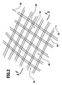
- the membrane 60 comprises a mat 80 formed of a fabric 82, the fabric 82 having first fibers 84 extending approximately parallel to a first direction 85 and second fibers 86 extending approximately parallel to a second direction 87, thus crossing each other and interwoven with each other, so that in the fabric 82, the fibers 84 and 86 are fixed relative to each other.
- the mat 80 comprises a single fabric layer 88, that is, a layer of fibers 84 extending in a ply surface 90 and a ply of fibers 86 extending in the ply surface 90 which overlap at intersection areas.
- the fibers 84 and 86 may be made of different materials, as long as these materials are high temperature resistant and heat shock resistant.
- high-temperature resistant is understood to mean a temperature resistance to temperatures of more than 700.degree. C., more preferably more than 900.degree. C. and even better more than 1200.degree.
- thermal shock resistance is understood as meaning a shock resistance of the fibers 84 and 86 to changes in temperature by more than 500 ° K in less than one second, more preferably more than 700 ° K in less than one second, which arises in particular because the fiber or fiber Also, a fiber composite typically have a small coefficient of thermal expansion.
- the fibers 84 and 86 are formed as carbon fibers in an exemplary embodiment.
- the fibers 84 and 86 it is conceivable to form the fibers 84 and 86 but also as silicon carbide fibers or fibers of another ceramic material.
- fibers 84 of a first material and fibers 86 of a second material for one and the same fabric, or to use fibers of different materials even within the fibers 84.
- the membrane 60 may be constructed solely of the layer 88 of fabric 82.
- the membrane 60 is provided on its front side 66 with the coating 76 which coats the fibers 84 and 86 and on the back 68 with the coating 74 which also coats the fibers 84 and 86 in that region.
- the coatings 76 and 74 may be composed of different materials and may also be applied by different processes.
- silicon nitride and / or silicon carbide which can be applied either by plasma spraying and / or by PVD (Physical Vapor Deposition) and / or by CVD (Chemical Vapor Deposition) and / or by CVI (Chemical Vapor Infiltration) can be used as materials for the coatings are.
- PVD Physical Vapor Deposition
- CVD Chemical Vapor Deposition
- CVI Chemical Vapor Infiltration
- the coatings are applied by PVD or CVD.
- the coating material sets in cracks and depressions and on the other hand, after application of the coatings, the membrane 60 has a high degree of cleanliness.
- the coatings 74 and 76 preferably have a thickness ranging between about 100 ⁇ and about 3000 ⁇ .
- the membrane 60 has a low heat storage capacity or thermal mass, so that the membrane 60 on the one hand can heat up quickly and on the other hand, but after termination of Heating process by itself cools quickly, since at low thermal mass of the membrane 60 and the amount of heat stored in this low.
- the membrane 60 has a thickness that is at least 0.07 mm, for example, in the case that a single layer 88 of fibers 84, 86 is used.
- a useful maximum thickness of the membrane 60, especially when using multiple mats 80, is less than 1.5 mm, more preferably less than 1 mm, more preferably less than 0.5 mm.
- rapid thermal annealing processes can be achieved when the thermal mass of the membrane 60 is less than 50% of the substrate 12, more preferably less than 30% of the substrate 12.
- the coatings 74 and 76 can be used in the inventive membrane 60 not only to achieve advantageous radiation-absorbing and radiation-emitting properties, but also to protect the fibers 84 and 86, namely in that the coatings 74 and 76 in total the fibers 84 and cover 86 circumferentially.
- the membrane 60 is fixedly connected to a membrane carrier 100, which is designed, for example, as a carrier ring 102 whose one flat side 104, the membrane 60, for example, with its back 68 is fixed.
- the fixation can be done for example by forming a cohesive joint connection, for example by applying and melting of silicon, which adheres to both the support ring 102 and the membrane 60.
- the carrier ring 102 is, as in Fig. 5 shown, preferably also formed of a fabric 112 of fibers 114 and 116, wherein the fibers 114 and the fibers 116 extend crossing each other.
- the fibers 114 and 116 are embedded in a matrix 118, so that the carrier ring 102 is formed as a whole as a composite body.
- the fibers 114 and 116 in the support ring 102 have the same thermal expansion as the fibers 84 and 86 of the membrane 60, can be formed from the membrane 60 and the support ring 102, a membrane element 120, in which parallel to the surface 62, the thermal expansion of the Support ring 102 is substantially identical to the thermal expansion of the membrane 60, so that the support ring 102, which carries the membrane 60, the membrane 60 is always substantially in the direction of the surface 62 with the same force KM, which radially to a center 122 of Membrane element 120 extends, keeps taut, provided that the membrane 60 is fixed to the support ring 102 under a bias with the force KM.
- Such fixing under prestressing can also be achieved, for example, in that a joining connection between the membrane 60 and the carrier ring 102 takes place at different temperatures of the carrier ring 102 and the membrane 60, so that after the temperature compensation between the carrier ring 102 and the membrane 60, the membrane 60 is fixed to the carrier ring 102 with the defined preload KM.
- the prestress once achieved is substantially maintained even with large temperature changes, such as occur in the system according to the invention.
- a tensioning of the membrane 60 by the carrier ring 102 can also be achieved in that the carrier ring 102 is not constructed as a pure C / C composite material, but rather that the incorporation of silicon carbide takes place therein.
- silicon carbide has a greater thermal expansion than the carbon can be achieved so that the support ring 102 in the radial direction to the center 122 of the membrane element 120 upon reaching the relevant temperature range of several 100 ° C expands more than the membrane 60 and thereby the radial forces KM arise that keep the membrane 60 stretched at temperatures of several 100 ° C.
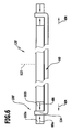
- a membrane element 120 ' In a second embodiment of a membrane element 120 'according to the invention, shown in FIG Fig. 6 , not only is a carrier ring 102 provided as a membrane carrier 100 ', but the membrane carrier 100' is formed by an inner support ring 102i and an outer support ring 102a, between which an edge region 124 of the membrane 60 is clamped by the inner support ring 102i with a Radial force KRi acts radially outwardly to the center 122, while the outer support ring 102a with a radial force KRa acts radially inwardly toward the center 122, so that the edge region 124 of the diaphragm 60 frictionally between the inner support ring 102i and the outer support ring 102a is trapped.
- a tensioning of the membrane 60 can additionally be achieved if the forces KM in the radial direction to the center 122 act outwards on the membrane 60 in the same way as in the first exemplary embodiment, for example, in that overall the membrane carrier 100 'receives the diaphragm 60 with prestressing and thus existing forces KM, which can be achieved, for example, by assembling the support rings 102i and 102a and the diaphragm 60 at different temperatures or by the support rings 102i and 102a having a greater thermal expansion than the ones Membrane 60, so that at the temperatures of several 100 ° C at which the system according to the invention works, due to the greater extent of the membrane support 100, the membrane 60 is held by this excited.
- the second embodiment is formed in the same manner as the first embodiment, so that in this regard the comments on the first embodiment can be fully incorporated by reference.
- the membrane 60 ' is not composed solely of the fibers 84 and 86, but in addition to the fibers 84 and 86 there is provided a matrix material 126 surrounding the fibers 84 and 86, which fibers 84 and 86 relative to each other fixed.
- the matrix material 126 may be carbon that has been formed by pyrolysis of a resin material embedding the fibers 84 and 86. But it is also conceivable that this matrix material 126 by additional silicization whole or at least partially converted to silicon carbide. In this case, at least on the surface of the fibers 84 and 86, the formation of silicon carbide takes place.
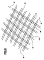
- the matrix material 126 may be selected such that between the fibers 84 and 86, as in Fig. 7 12, apertures 128 are still present such that the membrane 60 'is permeable to a medium, or the proportion of the matrix material 126 may be increased such that there are no more apertures 128 between the fibers 84 and 86 as in the fourth embodiment Fig. 8 shown.
- the third embodiment is formed in the same manner as the preceding embodiments, so that with respect to the remaining, not described in connection with the third embodiment, features, reference is made in full to the comments on the above embodiments.
- the matrix material 126 substantially completely fills the interstices between the fibers 84 and 86, however, if the matrix material 126 is pure carbon, it may be porous due to the pyrolysis of resin material itself and still have some fluid permeability , However, this permeability to a fluid can be prevented, for example, by siliconization with formation of silicon carbide and filling of the pores by free silicon.
- the permeability to a fluid can also be prevented, however, by providing the membrane 60 "according to the fourth embodiment with coatings, for example the coatings 74 and 76, which can be made from materials such that they close the pores of the matrix 126.
- the substrate 12 can be heated on its upper side 48 in the region of the structures 50.
- the bottom 46 facing lamps 71 between the outer housing 20 and the inner housing 24 are arranged, which radiate toward the bottom 46 of the substrate 12 and thus also heat the substrate 12 starting from the bottom.
- the substrate carrier 32 provided between the lamps 71 and the underside 46 of the substrate 12 is formed of the same material as the wall of the inner housing 24 and thus substantially transparent to the radiation of the lamps 71 so as not to absorb radiation.
- the substrate carrier 32 ' is not formed of a transparent material for the radiation of the lamps 71, but in the same way as the membrane 60, so that the substrate carrier 32 ' also acts as a heat transfer element and absorbs the radiation of the lamps 71 and in turn emits heat radiation due to its temperature in the direction of the bottom 46 of the substrate, so that in the area of the bottom 46 of the Substrate 12 has the opportunity to avoid the "pattern effect".
- the substrate carrier 32 has a dual function, it serves on the one hand to support the substrate 12 and on the other hand it acts in the same way as the membrane 60 for heating the substrate 12th
- the fifth embodiment is formed in the same manner as the preceding embodiments, so that reference is made in full to the description of the preceding embodiments with regard to the description of the other features.
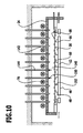
- FIG Fig. 10 is the diaphragm 60 according to the first embodiment, shown in FIG Fig. 2 and 3 , or according to the third embodiment, shown in FIG Fig. 7 formed, that is, that the membrane 60 is permeable to a fluid.
- a gas stream 150 which either comprises a used during the thermal treatment process gas or after completion of the thermal treatment of the substrate as rapid as possible cooling of the membrane 60 on the one hand and the substrate 12 permits.
- the openings 128 in such a way that the gas stream 150 entering the intermediate space 140 via the supply lines 144 passes through the membrane 60 and enters the substrate receiving space 30 as a substantially homogeneous diffuser gas stream 152 through the membrane 60 Supply process gas or the substrate 12 to cool.
- the membrane 60 in this embodiment, it is thus possible, after switching off the lamps 70, the membrane 60 "quickly cool by means of the gas stream 150 to end the heating of the substrate 12 through the membrane 60" as quickly as possible and further cooling the membrane 60 "from the substrate 12 radiated heat radiation in addition to absorb, so that overall the cooling of the substrate 12 after completion of the heating of the same can be done faster.
- the openings 128 in their flow cross section for the gas flow 152 are so that, for example, in a central region 154 of the membrane 60 ', the flow cross section of the openings 128 has a maximum value and has a minimum value in an outer region 156 of the membrane 60'.
- the flow cross-section 128 preferably varies in such a way that it is smaller by more than a factor of 2 in the outer region 156, preferably by a factor of approximately 3, than in the central region 154.
- a particularly favorable solution provides that the flow cross section of the openings 128, starting from the central region 154 of the membrane to the outer region 156, changes continuously, preferably linearly, to the specified extent.
- the homogeneous diffuse gas flow 152 can be formed such that a flow velocity thereof radially outward from the central region 154 to the outer regions 156 is at least approximately equal, with the gas in Radial direction 158 flows between the membrane 60 'and the substrate to the outside and then flows further in this direction 158 from the substrate receiving space 30.
- FIG. 13 shown in FIG Fig. 13 is provided as a primary heat source 52, a membrane element 120 ', in which the membrane support 100 carries a substrate-side membrane 60s and a lamp-side membrane 601, between which a gap 160 is made.
- the lamp-side membrane 601 is first heated by the lamps 70, which in turn radiates and heats the substrate-side membrane 60s, the substrate-side membrane 60s then heating the substrate 12 in the region of its upper side 48 due to its radiation.
- the substrate-side membrane 60s is formed so as to be permeable to a medium, so that it is possible to introduce into the space 160 a gas flow 162 which is distributed in the space 160 and then causes this at least insofar as it passes through the membrane 60s, diffused gas stream 164 propagates in the substrate receiving space 30 in the direction of the substrate 12.
- This diffuse gas stream 164 can either be used to supply a process gas in the course of the thermal treatment of the substrate 12 or used to perform a rapid cooling of the substrate-side membrane 60s after the heating of the substrate 12 and thus the heating of the substrate 12 as abrupt as possible to terminate or optionally also additionally to obtain a cooling effect in the region of the top 48 of the substrate 12 in that the cooled membrane 60 acts as a heat sink.
- FIG Fig. 14 shown in FIG Fig. 14 is the membrane 60 according to the fourth embodiment according to Fig. 8 formed, wherein additionally the coating 74 on the side facing away from the substrate 12 of the membrane 60 is an electrically conductive coating.
- the coating 74 may be formed by a layer of silicon carbide.
- the heating of the membrane 60 "takes place inductively in this embodiment, so that instead of the lamps 70 between the outer housing 20 and the inner housing 24 is controlled according to the time course of the thermal treatment induction coil 170 is provided, the coil windings 172 generate a magnetic field, which in turn to eddy currents in the coating 74 of the membrane 60 "leads and thus causes heating of the membrane 60".
- the membrane serves 60 "in this ninth embodiment of the system according to the invention directly to produce the heat radiation provided according to the invention, so that in this embodiment, the heating rate and cooling rate compared to the embodiments with the lamps 70 can still be improved because the thermal mass is further reduced and only by the mass of the membrane 60 "is formed.
- the heating of the serving as a heat transfer element 52 membrane 60 is neither controlled by a time course of the thermal treatment lamps 70 nor by an induction coil 170, but by means of a heater representing a constant and held at a defined temperature embarkados 180, in contrast to the lamps 70 and the induction coil 170 is not controlled according to the temperature profile in the thermal treatment of the substrate 12 in terms of its temperature, but always maintains the constant temperature and is controlled by heating elements 182 kept at a constant temperature.
- the heating of the membrane 60 is primarily not by thermal radiation of the heating block 180, but by heat conduction via a gas, such as process gas, which is present in a gap 190 between the heating block 180 and the diaphragm 60 and thus the heating block 180 with the Membrane 60 thermally coupled.
- a gas such as process gas
- the gas also passes through the membrane 60, which is formed in the same way as in the first and second embodiments and thus gas-permeable, so that the gas also passes through the membrane 60 and enters the substrate receiving space 30, wherein the gas also Thermal coupling between the membrane 60 and the top 48 of the substrate 12 occurs, so that primarily by the gas, the necessary thermal coupling between the heating block 180 and finally the substrate 12 via the membrane 60 as a heat transfer element 52 takes place.
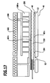
- the substrate 12 is guided in the substrate receiving space 30 in that both at a small distance from the top 48 of the substrate 12 and at a small distance from the bottom 46 of the substrate 12 extends the formed according to the first or second embodiment of the membrane 60, which of the Gas, which is respectively supplied to the intermediate space 190, is interspersed, so that in each case between the top 48 of the substrate 12 and the upper membrane 60o and the bottom 46 of the substrate 12 and the lower membrane 60u, a gas cushion 184 is formed, which the substrate 12th stably between the upper diaphragm 60o and the lower diaphragm 60u leads.
- the distance between the upper side 48 of the substrate 12 and the upper diaphragm 60o and the distance between the underside 46 of the substrate 12 and the lower diaphragm 60u less than 300 ⁇ m is even better less than 200 ⁇ m and, for example, on the order of approximately 150 ⁇ m.
- the distance between the upper heating block 180o and the upper diaphragm 60o and the heating block 180u and the lower diaphragm 60u is also of the order of less as 300 microns, even better less than 200 microns, so that here, too, a heat conduction via the gas in the space 190.
- a membrane element 200 is provided instead of the respective primary heat-generating membranes 60o and 60u, which in each case has a membrane 60s facing the substrate 12 and a membrane 60h facing the heating block 180, which are arranged at a distance from one another, so that they interpose between them Gap 210 forms to which gas can be fed, which, in the same way as in the tenth embodiment, penetrates the membrane 60s and contributes to the formation of the gas cushion 184, which guides the substrate 12.
- the diaphragm 60h is designed as a gas-tight membrane, so that the gas entering the gap 210 flows exclusively in the direction of the substrate for forming the gas cushion 184, but not in the direction of the heating block 180.
- the clearance 190 between the heating block 180 and the diaphragm 60h of the diaphragm member 200 is minimized to obtain heat conduction between the heating block 180 and the diaphragm 60h of the diaphragm member 200 via the gas so that the clearance 190 is between the heating block 180 and the diaphragm 60h have the same dimensions as in the tenth embodiment.
- the space 190 to supply a heat coupling effecting gas.
- the heat coupling between the membranes 60h and 60s of the membrane element 200 also takes place via the gas present in the space 210, wherein also the distance of the membranes 60s and 60h is so small that such heat coupling via the gas is efficient, ie also in one area less than 300 ⁇ m, more preferably less than 200 ⁇ m.
- the membrane element 200 now also makes it possible to also stop the heating block 180 away from the membrane element 200 and at the same time supply cold gas, for example even liquid nitrogen, to the space 210 in the membrane element 200 a rapid cooling of at least the substrate 12 facing the membrane 60s allows and thus simultaneously a rapid cooling of the top surface 48 of the substrate 12, since the top 48 of the substrate 12 is still thermally coupled to the membrane 60s via the gas cushion 184.
- cold gas for example even liquid nitrogen
- the diaphragm member 200 may be mechanically supported in the eleventh embodiment so as to remain in position regardless of the movement of the heating blocks 180.
- FIG. 2 shows that the membrane element is supported relative to the heating block 180 by the gas cushion provided in the intermediate space 190 and in turn supports the substrate 12 by forming the gas cushion 184 between the membrane 60s and the respective side of the substrate 12.
- the membrane element 200 is thus supported on the one hand with respect to the respective heating block 180 by a gas cushion and on the other hand it in turn supports the substrate 12 by a gas cushion so that the membrane element 200 does not have to be mechanically fixed relative to a housing.
- the eleventh embodiment is provided with the same reference numerals inasmuch as the same parts as used in any of the preceding embodiments are used, so that also with respect to the description and function of these parts, reference may be made in full to the comments on the above embodiments.
Landscapes
- Separation Using Semi-Permeable Membranes (AREA)
- Container, Conveyance, Adherence, Positioning, Of Wafer (AREA)
Applications Claiming Priority (1)
| Application Number | Priority Date | Filing Date | Title |
|---|---|---|---|
| DE102007054526A DE102007054526A1 (de) | 2007-11-07 | 2007-11-07 | Wärmetransferelement und Anlage zur thermischen Behandlung von Substraten |
Publications (3)
| Publication Number | Publication Date |
|---|---|
| EP2058841A2 true EP2058841A2 (fr) | 2009-05-13 |
| EP2058841A3 EP2058841A3 (fr) | 2012-05-02 |
| EP2058841B1 EP2058841B1 (fr) | 2014-05-21 |
Family
ID=40010624
Family Applications (1)
| Application Number | Title | Priority Date | Filing Date |
|---|---|---|---|
| EP08167941.7A Not-in-force EP2058841B1 (fr) | 2007-11-07 | 2008-10-30 | Elément de transfert de chaleur et dispositif pour le traitement thermique de substrats |
Country Status (2)
| Country | Link |
|---|---|
| EP (1) | EP2058841B1 (fr) |
| DE (1) | DE102007054526A1 (fr) |
Cited By (3)
| Publication number | Priority date | Publication date | Assignee | Title |
|---|---|---|---|---|
| CN109496241A (zh) * | 2016-08-24 | 2019-03-19 | 西屋电气有限责任公司 | 制造SiC复合陶瓷的工艺 |
| IT201800009953A1 (it) | 2018-10-31 | 2020-05-01 | Petroceramics Spa | Metodo ed un assieme di infiltrazione e la deposizione rapida da fase vapore di componenti porosi |
| EP3647459A1 (fr) | 2018-10-31 | 2020-05-06 | Petroceramics S.p.A. | Procédé et ensemble par infiltration chimique en phase vapeur de composants poreux |
Families Citing this family (2)
| Publication number | Priority date | Publication date | Assignee | Title |
|---|---|---|---|---|
| DE102013218883B4 (de) * | 2013-09-19 | 2018-12-06 | Siltronic Ag | Vorrichtung und Verfahren zum Abscheiden von Halbleitermaterial aus einer Gasphase auf eine Substratscheibe |
| DE102017204258B4 (de) | 2017-03-14 | 2023-08-17 | Schunk Kohlenstofftechnik Gmbh | Verfahren zur Herstellung eines porösen Körpers |
Citations (3)
| Publication number | Priority date | Publication date | Assignee | Title |
|---|---|---|---|---|
| DE3922539A1 (de) | 1989-07-08 | 1991-01-10 | Sintec Keramik Gmbh | Verfahren zur herstellung von hochpraezisen heizelementen aus c f c |
| WO2002061808A2 (fr) | 2001-01-30 | 2002-08-08 | Tokyo Electron Limited | Appareil de traitement thermique et anneau de support de plaquettes |
| WO2007105798A1 (fr) | 2006-03-16 | 2007-09-20 | Ihi Corporation | Plaque de protection thermique destinee a un appareil de recuit de substrat |
Family Cites Families (1)
| Publication number | Priority date | Publication date | Assignee | Title |
|---|---|---|---|---|
| DE10357698A1 (de) * | 2003-12-09 | 2005-07-14 | Schunk Kohlenstofftechnik Gmbh | Träger für zu behandelnde Gegenstände sowie Verfahren zur Herstellung eines solchen |
-
2007
- 2007-11-07 DE DE102007054526A patent/DE102007054526A1/de not_active Ceased
-
2008
- 2008-10-30 EP EP08167941.7A patent/EP2058841B1/fr not_active Not-in-force
Patent Citations (3)
| Publication number | Priority date | Publication date | Assignee | Title |
|---|---|---|---|---|
| DE3922539A1 (de) | 1989-07-08 | 1991-01-10 | Sintec Keramik Gmbh | Verfahren zur herstellung von hochpraezisen heizelementen aus c f c |
| WO2002061808A2 (fr) | 2001-01-30 | 2002-08-08 | Tokyo Electron Limited | Appareil de traitement thermique et anneau de support de plaquettes |
| WO2007105798A1 (fr) | 2006-03-16 | 2007-09-20 | Ihi Corporation | Plaque de protection thermique destinee a un appareil de recuit de substrat |
Cited By (4)
| Publication number | Priority date | Publication date | Assignee | Title |
|---|---|---|---|---|
| CN109496241A (zh) * | 2016-08-24 | 2019-03-19 | 西屋电气有限责任公司 | 制造SiC复合陶瓷的工艺 |
| IT201800009953A1 (it) | 2018-10-31 | 2020-05-01 | Petroceramics Spa | Metodo ed un assieme di infiltrazione e la deposizione rapida da fase vapore di componenti porosi |
| EP3647459A1 (fr) | 2018-10-31 | 2020-05-06 | Petroceramics S.p.A. | Procédé et ensemble par infiltration chimique en phase vapeur de composants poreux |
| US11981607B2 (en) | 2018-10-31 | 2024-05-14 | Petroceramics S.P.A. | Method and assembly for infiltration and rapid phase deposition of porous components |
Also Published As
| Publication number | Publication date |
|---|---|
| DE102007054526A1 (de) | 2009-05-14 |
| EP2058841A3 (fr) | 2012-05-02 |
| EP2058841B1 (fr) | 2014-05-21 |
Similar Documents
| Publication | Publication Date | Title |
|---|---|---|
| EP2058841B1 (fr) | Elément de transfert de chaleur et dispositif pour le traitement thermique de substrats | |
| DE3531789A1 (de) | Traeger zur verwendung bei der aufbringung einer schicht auf eine silicium-halbleiterscheibe | |
| DE102009007587B4 (de) | Verfahren und Vorrichtung zur Beschichtung von Substraten aus der Dampfphase | |
| DE19544525A1 (de) | Verfahren zur Wärmebehandlung eines Halbleiterkörpers | |
| EP3699328B1 (fr) | Procédé de fabrication pour un monocristal volumique de sic et dispositif de croissance correspondant | |
| EP1874976A2 (fr) | Dispositif de chauffage, installation de revetement et procede pour mettre en oeuvre la vaporisation ou la sublimation de matieres de revetement | |
| WO2016162088A1 (fr) | Dispositif et procédé pour relier deux substrats | |
| DE69930266T2 (de) | Material zum ziehen von sic-einkristallen und verfahren zur herstellung von sic-einkristallen | |
| DE3303568C2 (de) | Verfahren zum hitzebeständigen Verbinden von Graphitplatten untereinander oder mit metallischen Untergründen | |
| DE2315894C3 (de) | Verfahren zum Eindiffundieren von Dotierstoff in einen Halbleiterkörper | |
| EP3523637B1 (fr) | Microsysteme thermiquement isolant | |
| EP1131848B1 (fr) | Procede de production d'un semiconducteur comportant une zone d'arret | |
| DE102009047751B4 (de) | Brenneranordnung | |
| DE102010011156A1 (de) | Vorrichtung zur thermischen Behandlung von Halbleitersubstraten | |
| DE2621418C2 (de) | Verfahren und Vorrichtung zum Dotieren von Halbleiterplättchen | |
| EP1590510A2 (fr) | Dispositif pour realiser des passages electriquement conducteurs dans une tranche de semi-conducteur, au moyen d'une migration thermique | |
| DE2110865B2 (de) | Rohrofen | |
| DE102009014564A1 (de) | Bremsvorrichtung und Verfahren zur Herstellung einer Bremsvorrichtung | |
| DE102007054527A1 (de) | Neue Aufheizblöcke | |
| DE19750517A1 (de) | Hitzeschild | |
| WO2020049187A1 (fr) | Fermeture de tube pour tube de traitement et unité de traitement | |
| EP1821087B1 (fr) | Radiateur thermique | |
| DE102018220013A1 (de) | Verfahren zur Herstellung thermoelektrischer Elemente mittels Drucktechnologie | |
| DE102014108925A1 (de) | Substratbeschichtungseinrichtung und Bedampfungsverfahren | |
| DE3239253A1 (de) | Rohrcuvette fuer die atomabsorptionsspektrometrie |
Legal Events
| Date | Code | Title | Description |
|---|---|---|---|
| PUAI | Public reference made under article 153(3) epc to a published international application that has entered the european phase |
Free format text: ORIGINAL CODE: 0009012 |
|
| AK | Designated contracting states |
Kind code of ref document: A2 Designated state(s): AT BE BG CH CY CZ DE DK EE ES FI FR GB GR HR HU IE IS IT LI LT LU LV MC MT NL NO PL PT RO SE SI SK TR |
|
| AX | Request for extension of the european patent |
Extension state: AL BA MK RS |
|
| REG | Reference to a national code |
Ref country code: DE Ref legal event code: R079 Ref document number: 502008011794 Country of ref document: DE Free format text: PREVIOUS MAIN CLASS: H01L0021000000 Ipc: H01L0021670000 |
|
| PUAL | Search report despatched |
Free format text: ORIGINAL CODE: 0009013 |
|
| AK | Designated contracting states |
Kind code of ref document: A3 Designated state(s): AT BE BG CH CY CZ DE DK EE ES FI FR GB GR HR HU IE IS IT LI LT LU LV MC MT NL NO PL PT RO SE SI SK TR |
|
| AX | Request for extension of the european patent |
Extension state: AL BA MK RS |
|
| RIC1 | Information provided on ipc code assigned before grant |
Ipc: H01L 21/324 20060101ALI20120328BHEP Ipc: H01L 21/67 20060101AFI20120328BHEP |
|
| 17P | Request for examination filed |
Effective date: 20121102 |
|
| 17Q | First examination report despatched |
Effective date: 20121128 |
|
| AKX | Designation fees paid |
Designated state(s): AT BE BG CH CY CZ DE DK EE ES FI FR GB GR HR HU IE IS IT LI LT LU LV MC MT NL NO PL PT RO SE SI SK TR |
|
| GRAP | Despatch of communication of intention to grant a patent |
Free format text: ORIGINAL CODE: EPIDOSNIGR1 |
|
| INTG | Intention to grant announced |
Effective date: 20131015 |
|
| GRAS | Grant fee paid |
Free format text: ORIGINAL CODE: EPIDOSNIGR3 |
|
| GRAP | Despatch of communication of intention to grant a patent |
Free format text: ORIGINAL CODE: EPIDOSNIGR1 |
|
| INTG | Intention to grant announced |
Effective date: 20140314 |
|
| GRAA | (expected) grant |
Free format text: ORIGINAL CODE: 0009210 |
|
| AK | Designated contracting states |
Kind code of ref document: B1 Designated state(s): AT BE BG CH CY CZ DE DK EE ES FI FR GB GR HR HU IE IS IT LI LT LU LV MC MT NL NO PL PT RO SE SI SK TR |
|
| REG | Reference to a national code |
Ref country code: GB Ref legal event code: FG4D Free format text: NOT ENGLISH |
|
| REG | Reference to a national code |
Ref country code: CH Ref legal event code: EP |
|
| REG | Reference to a national code |
Ref country code: AT Ref legal event code: REF Ref document number: 669975 Country of ref document: AT Kind code of ref document: T Effective date: 20140615 |
|
| REG | Reference to a national code |
Ref country code: IE Ref legal event code: FG4D Free format text: LANGUAGE OF EP DOCUMENT: GERMAN |
|
| REG | Reference to a national code |
Ref country code: DE Ref legal event code: R096 Ref document number: 502008011794 Country of ref document: DE Effective date: 20140703 |
|
| REG | Reference to a national code |
Ref country code: NL Ref legal event code: VDEP Effective date: 20140521 |
|
| REG | Reference to a national code |
Ref country code: LT Ref legal event code: MG4D |
|
| PG25 | Lapsed in a contracting state [announced via postgrant information from national office to epo] |
Ref country code: FI Free format text: LAPSE BECAUSE OF FAILURE TO SUBMIT A TRANSLATION OF THE DESCRIPTION OR TO PAY THE FEE WITHIN THE PRESCRIBED TIME-LIMIT Effective date: 20140521 Ref country code: NO Free format text: LAPSE BECAUSE OF FAILURE TO SUBMIT A TRANSLATION OF THE DESCRIPTION OR TO PAY THE FEE WITHIN THE PRESCRIBED TIME-LIMIT Effective date: 20140821 Ref country code: IS Free format text: LAPSE BECAUSE OF FAILURE TO SUBMIT A TRANSLATION OF THE DESCRIPTION OR TO PAY THE FEE WITHIN THE PRESCRIBED TIME-LIMIT Effective date: 20140921 Ref country code: LT Free format text: LAPSE BECAUSE OF FAILURE TO SUBMIT A TRANSLATION OF THE DESCRIPTION OR TO PAY THE FEE WITHIN THE PRESCRIBED TIME-LIMIT Effective date: 20140521 Ref country code: GR Free format text: LAPSE BECAUSE OF FAILURE TO SUBMIT A TRANSLATION OF THE DESCRIPTION OR TO PAY THE FEE WITHIN THE PRESCRIBED TIME-LIMIT Effective date: 20140822 |
|
| PG25 | Lapsed in a contracting state [announced via postgrant information from national office to epo] |
Ref country code: LV Free format text: LAPSE BECAUSE OF FAILURE TO SUBMIT A TRANSLATION OF THE DESCRIPTION OR TO PAY THE FEE WITHIN THE PRESCRIBED TIME-LIMIT Effective date: 20140521 Ref country code: PL Free format text: LAPSE BECAUSE OF FAILURE TO SUBMIT A TRANSLATION OF THE DESCRIPTION OR TO PAY THE FEE WITHIN THE PRESCRIBED TIME-LIMIT Effective date: 20140521 Ref country code: SE Free format text: LAPSE BECAUSE OF FAILURE TO SUBMIT A TRANSLATION OF THE DESCRIPTION OR TO PAY THE FEE WITHIN THE PRESCRIBED TIME-LIMIT Effective date: 20140521 Ref country code: ES Free format text: LAPSE BECAUSE OF FAILURE TO SUBMIT A TRANSLATION OF THE DESCRIPTION OR TO PAY THE FEE WITHIN THE PRESCRIBED TIME-LIMIT Effective date: 20140521 Ref country code: HR Free format text: LAPSE BECAUSE OF FAILURE TO SUBMIT A TRANSLATION OF THE DESCRIPTION OR TO PAY THE FEE WITHIN THE PRESCRIBED TIME-LIMIT Effective date: 20140521 |
|
| PG25 | Lapsed in a contracting state [announced via postgrant information from national office to epo] |
Ref country code: PT Free format text: LAPSE BECAUSE OF FAILURE TO SUBMIT A TRANSLATION OF THE DESCRIPTION OR TO PAY THE FEE WITHIN THE PRESCRIBED TIME-LIMIT Effective date: 20140922 |
|
| PG25 | Lapsed in a contracting state [announced via postgrant information from national office to epo] |
Ref country code: RO Free format text: LAPSE BECAUSE OF FAILURE TO SUBMIT A TRANSLATION OF THE DESCRIPTION OR TO PAY THE FEE WITHIN THE PRESCRIBED TIME-LIMIT Effective date: 20140521 Ref country code: EE Free format text: LAPSE BECAUSE OF FAILURE TO SUBMIT A TRANSLATION OF THE DESCRIPTION OR TO PAY THE FEE WITHIN THE PRESCRIBED TIME-LIMIT Effective date: 20140521 Ref country code: CZ Free format text: LAPSE BECAUSE OF FAILURE TO SUBMIT A TRANSLATION OF THE DESCRIPTION OR TO PAY THE FEE WITHIN THE PRESCRIBED TIME-LIMIT Effective date: 20140521 Ref country code: SK Free format text: LAPSE BECAUSE OF FAILURE TO SUBMIT A TRANSLATION OF THE DESCRIPTION OR TO PAY THE FEE WITHIN THE PRESCRIBED TIME-LIMIT Effective date: 20140521 Ref country code: DK Free format text: LAPSE BECAUSE OF FAILURE TO SUBMIT A TRANSLATION OF THE DESCRIPTION OR TO PAY THE FEE WITHIN THE PRESCRIBED TIME-LIMIT Effective date: 20140521 |
|
| REG | Reference to a national code |
Ref country code: DE Ref legal event code: R097 Ref document number: 502008011794 Country of ref document: DE |
|
| PG25 | Lapsed in a contracting state [announced via postgrant information from national office to epo] |
Ref country code: NL Free format text: LAPSE BECAUSE OF FAILURE TO SUBMIT A TRANSLATION OF THE DESCRIPTION OR TO PAY THE FEE WITHIN THE PRESCRIBED TIME-LIMIT Effective date: 20140521 |
|
| PLBE | No opposition filed within time limit |
Free format text: ORIGINAL CODE: 0009261 |
|
| STAA | Information on the status of an ep patent application or granted ep patent |
Free format text: STATUS: NO OPPOSITION FILED WITHIN TIME LIMIT |
|
| 26N | No opposition filed |
Effective date: 20150224 |
|
| PG25 | Lapsed in a contracting state [announced via postgrant information from national office to epo] |
Ref country code: IT Free format text: LAPSE BECAUSE OF FAILURE TO SUBMIT A TRANSLATION OF THE DESCRIPTION OR TO PAY THE FEE WITHIN THE PRESCRIBED TIME-LIMIT Effective date: 20140521 |
|
| PG25 | Lapsed in a contracting state [announced via postgrant information from national office to epo] |
Ref country code: MC Free format text: LAPSE BECAUSE OF FAILURE TO SUBMIT A TRANSLATION OF THE DESCRIPTION OR TO PAY THE FEE WITHIN THE PRESCRIBED TIME-LIMIT Effective date: 20140521 Ref country code: LU Free format text: LAPSE BECAUSE OF FAILURE TO SUBMIT A TRANSLATION OF THE DESCRIPTION OR TO PAY THE FEE WITHIN THE PRESCRIBED TIME-LIMIT Effective date: 20141030 |
|
| REG | Reference to a national code |
Ref country code: CH Ref legal event code: PL |
|
| REG | Reference to a national code |
Ref country code: DE Ref legal event code: R097 Ref document number: 502008011794 Country of ref document: DE Effective date: 20150224 |
|
| GBPC | Gb: european patent ceased through non-payment of renewal fee |
Effective date: 20141030 |
|
| PG25 | Lapsed in a contracting state [announced via postgrant information from national office to epo] |
Ref country code: BE Free format text: LAPSE BECAUSE OF NON-PAYMENT OF DUE FEES Effective date: 20141031 |
|
| REG | Reference to a national code |
Ref country code: DE Ref legal event code: R082 Ref document number: 502008011794 Country of ref document: DE Representative=s name: HOEGER, STELLRECHT & PARTNER PATENTANWAELTE MB, DE |
|
| REG | Reference to a national code |
Ref country code: IE Ref legal event code: MM4A |
|
| PG25 | Lapsed in a contracting state [announced via postgrant information from national office to epo] |
Ref country code: CH Free format text: LAPSE BECAUSE OF NON-PAYMENT OF DUE FEES Effective date: 20141031 Ref country code: SI Free format text: LAPSE BECAUSE OF FAILURE TO SUBMIT A TRANSLATION OF THE DESCRIPTION OR TO PAY THE FEE WITHIN THE PRESCRIBED TIME-LIMIT Effective date: 20140521 Ref country code: GB Free format text: LAPSE BECAUSE OF NON-PAYMENT OF DUE FEES Effective date: 20141030 Ref country code: LI Free format text: LAPSE BECAUSE OF NON-PAYMENT OF DUE FEES Effective date: 20141031 |
|
| REG | Reference to a national code |
Ref country code: FR Ref legal event code: ST Effective date: 20150630 |
|
| PG25 | Lapsed in a contracting state [announced via postgrant information from national office to epo] |
Ref country code: FR Free format text: LAPSE BECAUSE OF NON-PAYMENT OF DUE FEES Effective date: 20141031 |
|
| PG25 | Lapsed in a contracting state [announced via postgrant information from national office to epo] |
Ref country code: IE Free format text: LAPSE BECAUSE OF NON-PAYMENT OF DUE FEES Effective date: 20141030 |
|
| REG | Reference to a national code |
Ref country code: AT Ref legal event code: MM01 Ref document number: 669975 Country of ref document: AT Kind code of ref document: T Effective date: 20141030 |
|
| PG25 | Lapsed in a contracting state [announced via postgrant information from national office to epo] |
Ref country code: AT Free format text: LAPSE BECAUSE OF NON-PAYMENT OF DUE FEES Effective date: 20141030 |
|
| PG25 | Lapsed in a contracting state [announced via postgrant information from national office to epo] |
Ref country code: BG Free format text: LAPSE BECAUSE OF FAILURE TO SUBMIT A TRANSLATION OF THE DESCRIPTION OR TO PAY THE FEE WITHIN THE PRESCRIBED TIME-LIMIT Effective date: 20140521 |
|
| PG25 | Lapsed in a contracting state [announced via postgrant information from national office to epo] |
Ref country code: CY Free format text: LAPSE BECAUSE OF FAILURE TO SUBMIT A TRANSLATION OF THE DESCRIPTION OR TO PAY THE FEE WITHIN THE PRESCRIBED TIME-LIMIT Effective date: 20140521 |
|
| PG25 | Lapsed in a contracting state [announced via postgrant information from national office to epo] |
Ref country code: MT Free format text: LAPSE BECAUSE OF FAILURE TO SUBMIT A TRANSLATION OF THE DESCRIPTION OR TO PAY THE FEE WITHIN THE PRESCRIBED TIME-LIMIT Effective date: 20140521 Ref country code: HU Free format text: LAPSE BECAUSE OF FAILURE TO SUBMIT A TRANSLATION OF THE DESCRIPTION OR TO PAY THE FEE WITHIN THE PRESCRIBED TIME-LIMIT; INVALID AB INITIO Effective date: 20081030 Ref country code: TR Free format text: LAPSE BECAUSE OF FAILURE TO SUBMIT A TRANSLATION OF THE DESCRIPTION OR TO PAY THE FEE WITHIN THE PRESCRIBED TIME-LIMIT Effective date: 20140521 |
|
| PGFP | Annual fee paid to national office [announced via postgrant information from national office to epo] |
Ref country code: DE Payment date: 20180917 Year of fee payment: 11 |
|
| REG | Reference to a national code |
Ref country code: DE Ref legal event code: R082 Ref document number: 502008011794 Country of ref document: DE Representative=s name: HOEGER, STELLRECHT & PARTNER PATENTANWAELTE MB, DE |
|
| REG | Reference to a national code |
Ref country code: DE Ref legal event code: R119 Ref document number: 502008011794 Country of ref document: DE |
|
| PG25 | Lapsed in a contracting state [announced via postgrant information from national office to epo] |
Ref country code: DE Free format text: LAPSE BECAUSE OF NON-PAYMENT OF DUE FEES Effective date: 20200501 |