EP3647459A1 - Procédé et ensemble par infiltration chimique en phase vapeur de composants poreux - Google Patents
Procédé et ensemble par infiltration chimique en phase vapeur de composants poreux Download PDFInfo
- Publication number
- EP3647459A1 EP3647459A1 EP18203800.0A EP18203800A EP3647459A1 EP 3647459 A1 EP3647459 A1 EP 3647459A1 EP 18203800 A EP18203800 A EP 18203800A EP 3647459 A1 EP3647459 A1 EP 3647459A1
- Authority
- EP
- European Patent Office
- Prior art keywords
- crucible
- pressure
- additional steps
- gas
- kpa
- Prior art date
- Legal status (The legal status is an assumption and is not a legal conclusion. Google has not performed a legal analysis and makes no representation as to the accuracy of the status listed.)
- Withdrawn
Links
Images



Classifications
-
- C—CHEMISTRY; METALLURGY
- C04—CEMENTS; CONCRETE; ARTIFICIAL STONE; CERAMICS; REFRACTORIES
- C04B—LIME, MAGNESIA; SLAG; CEMENTS; COMPOSITIONS THEREOF, e.g. MORTARS, CONCRETE OR LIKE BUILDING MATERIALS; ARTIFICIAL STONE; CERAMICS; REFRACTORIES; TREATMENT OF NATURAL STONE
- C04B35/00—Shaped ceramic products characterised by their composition; Ceramics compositions; Processing powders of inorganic compounds preparatory to the manufacturing of ceramic products
- C04B35/71—Ceramic products containing macroscopic reinforcing agents
- C04B35/78—Ceramic products containing macroscopic reinforcing agents containing non-metallic materials
- C04B35/80—Fibres, filaments, whiskers, platelets, or the like
- C04B35/83—Carbon fibres in a carbon matrix
-
- C—CHEMISTRY; METALLURGY
- C04—CEMENTS; CONCRETE; ARTIFICIAL STONE; CERAMICS; REFRACTORIES
- C04B—LIME, MAGNESIA; SLAG; CEMENTS; COMPOSITIONS THEREOF, e.g. MORTARS, CONCRETE OR LIKE BUILDING MATERIALS; ARTIFICIAL STONE; CERAMICS; REFRACTORIES; TREATMENT OF NATURAL STONE
- C04B41/00—After-treatment of mortars, concrete, artificial stone or ceramics; Treatment of natural stone
- C04B41/009—After-treatment of mortars, concrete, artificial stone or ceramics; Treatment of natural stone characterised by the material treated
-
- C—CHEMISTRY; METALLURGY
- C04—CEMENTS; CONCRETE; ARTIFICIAL STONE; CERAMICS; REFRACTORIES
- C04B—LIME, MAGNESIA; SLAG; CEMENTS; COMPOSITIONS THEREOF, e.g. MORTARS, CONCRETE OR LIKE BUILDING MATERIALS; ARTIFICIAL STONE; CERAMICS; REFRACTORIES; TREATMENT OF NATURAL STONE
- C04B41/00—After-treatment of mortars, concrete, artificial stone or ceramics; Treatment of natural stone
- C04B41/45—Coating or impregnating, e.g. injection in masonry, partial coating of green or fired ceramics, organic coating compositions for adhering together two concrete elements
- C04B41/457—Non-superficial impregnation or infiltration of the substrate
-
- C—CHEMISTRY; METALLURGY
- C23—COATING METALLIC MATERIAL; COATING MATERIAL WITH METALLIC MATERIAL; CHEMICAL SURFACE TREATMENT; DIFFUSION TREATMENT OF METALLIC MATERIAL; COATING BY VACUUM EVAPORATION, BY SPUTTERING, BY ION IMPLANTATION OR BY CHEMICAL VAPOUR DEPOSITION, IN GENERAL; INHIBITING CORROSION OF METALLIC MATERIAL OR INCRUSTATION IN GENERAL
- C23C—COATING METALLIC MATERIAL; COATING MATERIAL WITH METALLIC MATERIAL; SURFACE TREATMENT OF METALLIC MATERIAL BY DIFFUSION INTO THE SURFACE, BY CHEMICAL CONVERSION OR SUBSTITUTION; COATING BY VACUUM EVAPORATION, BY SPUTTERING, BY ION IMPLANTATION OR BY CHEMICAL VAPOUR DEPOSITION, IN GENERAL
- C23C16/00—Chemical coating by decomposition of gaseous compounds, without leaving reaction products of surface material in the coating, i.e. chemical vapour deposition [CVD] processes
- C23C16/04—Coating on selected surface areas, e.g. using masks
- C23C16/045—Coating cavities or hollow spaces, e.g. interior of tubes; Infiltration of porous substrates
-
- C—CHEMISTRY; METALLURGY
- C23—COATING METALLIC MATERIAL; COATING MATERIAL WITH METALLIC MATERIAL; CHEMICAL SURFACE TREATMENT; DIFFUSION TREATMENT OF METALLIC MATERIAL; COATING BY VACUUM EVAPORATION, BY SPUTTERING, BY ION IMPLANTATION OR BY CHEMICAL VAPOUR DEPOSITION, IN GENERAL; INHIBITING CORROSION OF METALLIC MATERIAL OR INCRUSTATION IN GENERAL
- C23C—COATING METALLIC MATERIAL; COATING MATERIAL WITH METALLIC MATERIAL; SURFACE TREATMENT OF METALLIC MATERIAL BY DIFFUSION INTO THE SURFACE, BY CHEMICAL CONVERSION OR SUBSTITUTION; COATING BY VACUUM EVAPORATION, BY SPUTTERING, BY ION IMPLANTATION OR BY CHEMICAL VAPOUR DEPOSITION, IN GENERAL
- C23C16/00—Chemical coating by decomposition of gaseous compounds, without leaving reaction products of surface material in the coating, i.e. chemical vapour deposition [CVD] processes
- C23C16/22—Chemical coating by decomposition of gaseous compounds, without leaving reaction products of surface material in the coating, i.e. chemical vapour deposition [CVD] processes characterised by the deposition of inorganic material, other than metallic material
- C23C16/26—Deposition of carbon only
-
- C—CHEMISTRY; METALLURGY
- C23—COATING METALLIC MATERIAL; COATING MATERIAL WITH METALLIC MATERIAL; CHEMICAL SURFACE TREATMENT; DIFFUSION TREATMENT OF METALLIC MATERIAL; COATING BY VACUUM EVAPORATION, BY SPUTTERING, BY ION IMPLANTATION OR BY CHEMICAL VAPOUR DEPOSITION, IN GENERAL; INHIBITING CORROSION OF METALLIC MATERIAL OR INCRUSTATION IN GENERAL
- C23C—COATING METALLIC MATERIAL; COATING MATERIAL WITH METALLIC MATERIAL; SURFACE TREATMENT OF METALLIC MATERIAL BY DIFFUSION INTO THE SURFACE, BY CHEMICAL CONVERSION OR SUBSTITUTION; COATING BY VACUUM EVAPORATION, BY SPUTTERING, BY ION IMPLANTATION OR BY CHEMICAL VAPOUR DEPOSITION, IN GENERAL
- C23C16/00—Chemical coating by decomposition of gaseous compounds, without leaving reaction products of surface material in the coating, i.e. chemical vapour deposition [CVD] processes
- C23C16/44—Chemical coating by decomposition of gaseous compounds, without leaving reaction products of surface material in the coating, i.e. chemical vapour deposition [CVD] processes characterised by the method of coating
- C23C16/4401—Means for minimising impurities, e.g. dust, moisture or residual gas, in the reaction chamber
-
- C—CHEMISTRY; METALLURGY
- C04—CEMENTS; CONCRETE; ARTIFICIAL STONE; CERAMICS; REFRACTORIES
- C04B—LIME, MAGNESIA; SLAG; CEMENTS; COMPOSITIONS THEREOF, e.g. MORTARS, CONCRETE OR LIKE BUILDING MATERIALS; ARTIFICIAL STONE; CERAMICS; REFRACTORIES; TREATMENT OF NATURAL STONE
- C04B2235/00—Aspects relating to ceramic starting mixtures or sintered ceramic products
- C04B2235/02—Composition of constituents of the starting material or of secondary phases of the final product
- C04B2235/30—Constituents and secondary phases not being of a fibrous nature
- C04B2235/46—Gases other than oxygen used as reactant, e.g. nitrogen used to make a nitride phase
-
- C—CHEMISTRY; METALLURGY
- C04—CEMENTS; CONCRETE; ARTIFICIAL STONE; CERAMICS; REFRACTORIES
- C04B—LIME, MAGNESIA; SLAG; CEMENTS; COMPOSITIONS THEREOF, e.g. MORTARS, CONCRETE OR LIKE BUILDING MATERIALS; ARTIFICIAL STONE; CERAMICS; REFRACTORIES; TREATMENT OF NATURAL STONE
- C04B2235/00—Aspects relating to ceramic starting mixtures or sintered ceramic products
- C04B2235/02—Composition of constituents of the starting material or of secondary phases of the final product
- C04B2235/50—Constituents or additives of the starting mixture chosen for their shape or used because of their shape or their physical appearance
- C04B2235/52—Constituents or additives characterised by their shapes
- C04B2235/5208—Fibers
- C04B2235/5216—Inorganic
- C04B2235/524—Non-oxidic, e.g. borides, carbides, silicides or nitrides
- C04B2235/5244—Silicon carbide
-
- C—CHEMISTRY; METALLURGY
- C04—CEMENTS; CONCRETE; ARTIFICIAL STONE; CERAMICS; REFRACTORIES
- C04B—LIME, MAGNESIA; SLAG; CEMENTS; COMPOSITIONS THEREOF, e.g. MORTARS, CONCRETE OR LIKE BUILDING MATERIALS; ARTIFICIAL STONE; CERAMICS; REFRACTORIES; TREATMENT OF NATURAL STONE
- C04B2235/00—Aspects relating to ceramic starting mixtures or sintered ceramic products
- C04B2235/02—Composition of constituents of the starting material or of secondary phases of the final product
- C04B2235/50—Constituents or additives of the starting mixture chosen for their shape or used because of their shape or their physical appearance
- C04B2235/52—Constituents or additives characterised by their shapes
- C04B2235/5208—Fibers
- C04B2235/5216—Inorganic
- C04B2235/524—Non-oxidic, e.g. borides, carbides, silicides or nitrides
- C04B2235/5248—Carbon, e.g. graphite
-
- C—CHEMISTRY; METALLURGY
- C04—CEMENTS; CONCRETE; ARTIFICIAL STONE; CERAMICS; REFRACTORIES
- C04B—LIME, MAGNESIA; SLAG; CEMENTS; COMPOSITIONS THEREOF, e.g. MORTARS, CONCRETE OR LIKE BUILDING MATERIALS; ARTIFICIAL STONE; CERAMICS; REFRACTORIES; TREATMENT OF NATURAL STONE
- C04B2235/00—Aspects relating to ceramic starting mixtures or sintered ceramic products
- C04B2235/60—Aspects relating to the preparation, properties or mechanical treatment of green bodies or pre-forms
- C04B2235/614—Gas infiltration of green bodies or pre-forms
-
- C—CHEMISTRY; METALLURGY
- C04—CEMENTS; CONCRETE; ARTIFICIAL STONE; CERAMICS; REFRACTORIES
- C04B—LIME, MAGNESIA; SLAG; CEMENTS; COMPOSITIONS THEREOF, e.g. MORTARS, CONCRETE OR LIKE BUILDING MATERIALS; ARTIFICIAL STONE; CERAMICS; REFRACTORIES; TREATMENT OF NATURAL STONE
- C04B2235/00—Aspects relating to ceramic starting mixtures or sintered ceramic products
- C04B2235/65—Aspects relating to heat treatments of ceramic bodies such as green ceramics or pre-sintered ceramics, e.g. burning, sintering or melting processes
- C04B2235/658—Atmosphere during thermal treatment
-
- C—CHEMISTRY; METALLURGY
- C04—CEMENTS; CONCRETE; ARTIFICIAL STONE; CERAMICS; REFRACTORIES
- C04B—LIME, MAGNESIA; SLAG; CEMENTS; COMPOSITIONS THEREOF, e.g. MORTARS, CONCRETE OR LIKE BUILDING MATERIALS; ARTIFICIAL STONE; CERAMICS; REFRACTORIES; TREATMENT OF NATURAL STONE
- C04B2235/00—Aspects relating to ceramic starting mixtures or sintered ceramic products
- C04B2235/70—Aspects relating to sintered or melt-casted ceramic products
- C04B2235/74—Physical characteristics
- C04B2235/77—Density
-
- C—CHEMISTRY; METALLURGY
- C04—CEMENTS; CONCRETE; ARTIFICIAL STONE; CERAMICS; REFRACTORIES
- C04B—LIME, MAGNESIA; SLAG; CEMENTS; COMPOSITIONS THEREOF, e.g. MORTARS, CONCRETE OR LIKE BUILDING MATERIALS; ARTIFICIAL STONE; CERAMICS; REFRACTORIES; TREATMENT OF NATURAL STONE
- C04B2235/00—Aspects relating to ceramic starting mixtures or sintered ceramic products
- C04B2235/70—Aspects relating to sintered or melt-casted ceramic products
- C04B2235/96—Properties of ceramic products, e.g. mechanical properties such as strength, toughness, wear resistance
- C04B2235/9607—Thermal properties, e.g. thermal expansion coefficient
Definitions
- the present invention relates to a method and an assembly for chemical vapor infiltration of porous components that are densified, for example when placed in stacks in a reactor.
- the present invention relates to devices, or assemblies, for chemical vapor infiltration and rapid densification of preforms, for example ceramic preforms.
- preforms for example ceramic preforms.
- the decomposition is obtained of a gaseous precursor, for example methane or methylchlorosilane, into its components, for example carbon and silicon carbide, which are deposited inside the porous preform composed of the same materials or compatible materials in the form of fibers, fabrics or other.
- a gaseous precursor for example methane or methylchlorosilane
- these porous components are substantially symmetrical circularly or annular with a central passage or opening, and they are placed in at least one stack, or pile, which defines an inner passage formed by the central openings of the components.
- the field of the invention resides in the fabrication of components that consist of a composite material comprising a porous substrate, or "preform", densified in its matrix, in particular in the production of brake disks made of composite material by means of the densification of preforms made of fibers, for example arranged in annular shape.
- parts made of composite material in particular parts made of composite material consisting of a fiber preform, for example carbon fibers or ceramic fibers, is obtained by densifying the matrix of the preform for example with chemical vapor infiltration methods.
- a fiber preform for example carbon fibers or ceramic fibers
- Densifying porous components by chemical vapor infiltration consists of placing the components in a reaction chamber, or crucible, of an infiltration system and of injecting a gas into the chamber in which one or more components of the gas form a precursor for the material of the matrix of the component to be deposited inside the component for the purpose of densifying it.
- the infiltration conditions in particular the concentration, the gas flow rate, the temperature and the pressure inside the chamber of the crucible, are selected to allow the gas to diffuse inside the accessible inner pores of the components so that the desired material is deposited therein by deposition on the fibers or generically on the material of the component.
- pyrolytic carbon or "pyrocarbon”
- the precursor of carbon is an alkane, an alkyl or an alkene, generally propane, methane or a mix of both.
- the infiltration is carried out at a temperature of approximately 1000°C at a pressure from approximately 1 kPa (10 mmBar) to approximately 15 kPa (150 mmBar), hence in fact in an environment defined as a vacuum, albeit not a high one.
- the substrates are brought to the desired temperature by means of heating produced by a susceptor, or inductor, which generally consists of graphite placed in a graphite chamber that defines the inner volume of the chamber of the furnace, forming a secondary induction circuit that is electromagnetically coupled with a primary induction circuit situated outside the chamber of the furnace.
- a susceptor or inductor, which generally consists of graphite placed in a graphite chamber that defines the inner volume of the chamber of the furnace, forming a secondary induction circuit that is electromagnetically coupled with a primary induction circuit situated outside the chamber of the furnace.
- the gas containing the precursor of the material to be deposited inside the preform is introduced in a longitudinal end of the chamber while the residual gas is evacuated from the opposite end where it is extracted by pump means or vacuum pumps.
- the gas is generally pre-heated before reaching the preforms that have to be densified, for example passing through perforated pre-heat plates.
- the entire chamber of the furnace is enclosed in a container, or vessel, so as to condition the environment that surrounds the susceptor and the walls of the furnace and above all the walls of the crucible contained therein.
- An imperative objective is to reduce pressure, thereby reducing the presence of oxygen in the furnace.
- the graphite, or the like is among the best suited material for arranging the entire setup inside the vessel because it is able to withstand high process temperatures, because it is a material with electrical properties, able to constitute resistors and susceptors, and because of its high thermal conductivity.
- the consequence of the use of this material is the need to protect these components against oxidation.
- oxygen is doubly dangerous, first of all because of the simultaneous presence of both a flammable gas such as methane and of high temperatures, and also because in an environment with oxygen the components made, for example, of graphite, deteriorate by oxidation.
- the process temperature is around 1000 - 1150°C.
- the atmosphere to which the chamber is exposed is strongly reducing because of the hydrogen produced by the methane decomposition reaction in the formation of the pyrolytic carbon that is deposited on the component to be densified.
- the reactor is closed in a second sealed container that works under vacuum or inert gas.
- these materials for example, Kanthal®
- these materials exhibit a severe reduction of the mechanical characteristics and are subject to degradation phenomena (for example, creep).
- reactors in particular Rapid-CVI reactors that use methane, are constructed with a graphite reaction chamber that can operate without any problems at the required temperatures and in reducing atmosphere.
- this chamber must be closed inside a second gas-tight vessel, usually made of stainless steel, appropriately insulated with carbon refractories and water-cooled, with consequent costs and complexity of the system.
- the resistors or inductors for heating the reactor are also made of graphite (see Figure 1 ).
- the graphite reaction chamber is not able to guarantee tightness against the reaction gases, whose escape into the outer vessel entails that the reaction chamber is deposited in thick and compact layers on the outer part of the chamber itself.
- the carbon is deposited in general on all the inner walls of the reactor, on the thermal insulators that progressively degrade, on the graphite bars of the resistor that have to be cleaned, and inside the recesses present in the support that tend to become obstructed.
- the present invention has allowed to have an oxidizing environment external to the crucible that leads to far less complex and costly systems, which allow the use of a type of furnace that is far simpler to build and operate and less expensive to maintain; for example furnaces for oxides.
- a crucible made of ceramic material is used, specifically one made of silicon-infiltrated silicon carbide.
- This material has a series of positive characteristics:
- this material has low density (3 kg/dm3) and hence does not need large, bulky and expensive support structures.
- reactors with volumes of at least 0.5 m3, to accommodate products to be densified of medium and large size as well.
- the refractory materials currently built with costly graphite foam can be replaced with more conventional and economical oxide-based refractories.
- Heating for example electrical heating
- graphite resistors with conventional Kantal® resistors, simpler and easier to drive electrically, with further system simplification thanks to the elimination of the transformer.
- an advantageous technological aspect is that of allowing the use of a different technology for the vacuum seals between the parts of the reactor (chamber and lid) and between them and the external pipes.
- the parts that constitute the reactor must operate at temperatures above 1000°C. Substantially, there are no materials that can be used as gaskets to provide a seal at these temperatures.
- the vacuum levels that have to be ensured inside the crucible are not high; therefore, it is sufficient that losses are lower than 0.2 mbar/min at 150 mbar of partial pressure.
- the adopted solution is not to insert any gasket but to place directly in contact the ceramic surfaces of the crucible that were previously ground and possibly lapped until obtaining a sufficiently low value of roughness to ensure the gas-tight contact between them.
- the pressure exerted between the different parts of the crucible because of their own weight and of the application of the vacuum inside the chamber of the crucible itself, is sufficient to ensure gas tightness throughout the range of operating conditions of the reactor.
- the external connections of the chamber were found to be at temperatures below 150°C in all operating conditions and hence for these junctions it is possible to use conventional high temperature gaskets (for example made of graphite).
- a condensation system is inserted along the connecting line between the reactor and the pump, to cool the gas and cause the tar to condensate. It is not necessary to achieve a nearly complete elimination, such as would fall within the limits of environmental emissions; it is sufficient to have enough tar reduction to allow use of a conventional dry pump to form the vacuum.
- the connecting pipes are jacketed and water-cooled. Their length is dimensioned so as to obtain a cooling of the gas to 60°C before entry into the pump.
- the different segments of the line are inclined and the tar that condenses is collected in a series of pits that can be opened for cleaning.
- This solution makes cleaning operations quick and infrequent, since the condensed tar is all collected without any dilution liquid to be disposed of.
- it is necessary to consider the reduction of the installation costs that does not regard only the elimination of the water tank and the connected components but also the elimination of the heat exchanger and of the refrigeration set which are currently necessary for the liquid ring pump which requires water at a constant temperature from 15° to 18°C to operate correctly. Thanks to the proposed solution, it is possible to use water coming from a cooling tower from 25 to 30°C.
- reducing atmosphere means, for example, a reducing atmosphere because of the hydrogen produced by the methane decomposition reaction in the formation of the pyrolytic carbon that is deposited on the component to be densified.
- a CVI, or chemical vapor infiltration, method for densifying at least one porous component 1 comprising at least the steps of:
- the chamber of the crucible is heated effectively and rapidly.
- the additional step is provided of bringing the pressure Pi inside the crucible 2 between 0.1 kPa and 25 kPa.
- a CVI, or chemical vapor infiltration, method for densifying at least one porous component 1 comprising at least the steps of:
- the additional step is provided of jacketing and/or coating said graphite crucible with an oxidation-resistant material.
- the additional step is provided of bringing the pressure Pi inside the crucible 2 between 0.1 kPa and 25 kPa.
- the additional step is provided of jacketing said crucible with an oxidation-resistant material.
- the additional step is provided wherein said coating is made of material comprising engobbio ®, or engobe.
- the additional step is provided wherein said coating is made of material comprising metals, for example refractory steels.
- the additional step is provided of obtaining a reducing environment inside the crucible (3) at steady state temperature and pressure and gas flushing.
- the additional step is provided of providing as the porous component 1 a component with matrix comprising fibers.
- the additional step is provided of providing as the porous component 1 a component with matrix comprising carbon fibers.
- the additional step is provided of providing as the porous component 1 a component with matrix comprising carbon fibers and pyrolytic carbon.
- the additional step is provided of providing as the porous component (1) a component with matrix comprising silicon carbide (SiC) fibers.
- the additional step is provided of providing as the porous component (1) a component with matrix comprising silicon carbide (SiC) fibers and pyrolytic carbon.
- SiC silicon carbide
- the additional step is provided of providing as the porous component (1) a component with matrix comprising silicon carbide (SiC) fibers and silicon carbide.
- SiC silicon carbide
- the additional step is provided of bringing the temperature Ti inside the crucible 3 between 900°C and 1300°C, preferably from 1050 to 1200°C.
- the additional step is provided of: upon reaching steady state temperature suitable for densification, obtaining a non-oxidizing environment inside the crucible (3); and wherein during the entire process, an oxidizing environment is maintained outside the crucible (3), wherein said external environment laps said crucible (3).
- the additional step is provided of: upon reaching temperature steady state suitable for densification, obtaining a reducing environment inside the crucible 3; and wherein, during the entire process, an oxidizing environment is maintained outside the crucible 3, wherein said external environment laps said crucible 3.
- the additional step is provided of providing said crucible 3 from a material that allows a thermal conductivity between 120 and 80 W/mK at 400°C.
- the additional step is provided of maintaining the pressure Pe outside the crucible 3 equal to ambient temperature, approximately 90 Kpa.
- the additional step is provided of obtaining, at steady state temperature and pressure suitable for densification, a reducing environment inside the crucible 3; and maintaining an oxidizing environment outside the crucible 3, wherein said external environment laps said crucible 3.
- the additional step is provided of regulating the flow of the gas (4) at the inlet (5) of the crucible (3) at a value between 0.1 I/min/dm3 and 10 l/min/dm3.
- the additional step is provided of regulating the flow of the gas 4 at the inlet 5 of the crucible 3 at a value between 1 l/min/dm3 and 5 l/min/dm3.
- the flushing of gas 4 can be slower to have a greater deposit of pyrolytic carbon that can be restructured into graphite with post-treatment, allowing a higher conductivity of the material.
- the additional step is provided of washing the crucible with nitrogen N2 during the start of the process, until the temperature of the crucible reaches a value close to the suitable value for the densification of the porous component 1 to transform it into a densified component 2.
- the additional step is provided of bringing the pressure (Pi) inside the crucible (3) between 1 kPa and 20 kPa.
- the additional step is provided of bringing the pressure Pi inside the crucible 3 between 10 kPa and 15 kPa.
- the additional step is provided wherein said crucible 3 avoids defining a thermal barrier between the environment outside the crucible and the environment inside the crucible.
- the additional step is provided of providing said crucible 3 so that its thermal conductivity is above 30 W/mK at 1000°C.
- the additional step is provided of maintaining the pressure Pe outside the crucible 3 equal to ambient temperature.
- the additional step is provided of regulating the flow of the gas 4 at the inlet 5 of the crucible 3 between 10 I/min and 60 I/min.
- the additional step is provided of bringing the pressure Pe outside the crucible 15 to no less than 15 KPa.
- the additional step is provided of maintaining a pressure difference between the environment inside the crucible 3 and outside the crucible 3, wherein the external environment has an overpressure with respect to the internal environment above 5 Kpa.
- the additional step is provided of maintaining a pressure difference between the environment inside the crucible 3 and outside the crucible 3, wherein the external environment has an overpressure with respect to the internal environment above 10 Kpa.
- the additional step is provided of, at the outlet of the crucible 3, separating the tar and/or cyclic aromatic hydrocarbons from the fumes 7 flowing out of the crucible.
- the exhaust gas flowing out of the crucible is used for burners that raise or maintain the temperature of the furnace. Thanks to this provision, it is possible to avoid the total separation of the tar and of the cyclic aromatic hydrocarbons because they are burned by the burners such as in a thermal destruction system.
- the additional step is provided of feeding to the crucible 3 as gas suitable for densification 4 methane, or butane, or ethane, or propane, or a combination thereof, and/or preferably methane with purity of 96%.
- the additional step is provided of bringing the exhaust gas 9 flowed out of the crucible 3 to ambient temperature Pe.
- the additional step is provided of accumulating the exhaust gas 9 at ambient temperature in an accumulation tank 50.
- the additional step is provided of using exhaust gas 9 flowed out of the crucible 3 and brought to ambient pressure Pe as fuel for feeding at least one burner 10 to bring and/or maintain the desired temperature Ti of the crucible 3.
- the additional step is provided of using, during the initial heating of the crucible 3, substantially pure methane to feed at least one burner 10 to bring the desired temperature Ti of the crucible 3.
- the additional step is provided of using, at steady state temperature, exhaust gas 9 flowed out of the crucible 3 and brought to ambient pressure Pe as fuel to feed at least one burner 10 and maintain the desired temperature Ti of the crucible 3.
- the additional step is provided of adding fuel gas 13 to the exhaust gas 9 flowing out of the crucible 3.
- the additional step is provided of placing the crucible 3 in a furnace for oxides 11.
- said furnaces are furnaces with oxidic refractories like aluminas and/or mullite in which cycles with oxidizing atmospheres are carried out.
- Kanthal® or super Kanthal® electrical resistors are used.
- a furnace of this type is the Nabertherm GmbH muffle furnace with maximum temperature of 1400°C and 400 liters of volume.
- the additional step is provided of maintaining the inner chamber of the furnace 12 in oxidizing environment.
- the additional step is provided of maintaining the inner chamber of the furnace 12 at the pressure that can reach ambient temperature Pe.
- the additional step is provided of bringing the pressure of the pressure inside the furnace 12 to the pressure at 30 - 90 Kpa.
- the additional step is provided of maintaining an ambient temperature Ta outside said furnace for oxides 11.
- the additional step is provided of providing a crucible 3 of silicon carbide SiC.
- the additional step is provided of providing a crucible 3 of silicon-infiltrated silicon carbide (Si-SiC).
- the additional step is provided of providing a crucible (3) of silicon-infiltrated (Si-SiC) sintered silicon carbide (SiC).
- the additional step is provided of providing a crucible 3 of boron carbide B4C.
- the additional step is provided of providing a crucible 3 of silicon-infiltrated boron carbide (Si-B4C).
- the additional step is provided of providing a crucible 3 of zirconium carbide ZrC.
- the additional step is provided of providing a crucible 3 of silicon-infiltrated zirconium carbide (Si-ZrC).
- the additional step is provided of providing a crucible 3 made of a combination of silicon carbide SiC, boron carbide B4C and zirconium carbide BZrC.
- the additional step is provided of providing a crucible 3 of sintered silicon carbide SiC.
- the crucible is 100% of sintered SiC or silicon-infiltrated SiC, for example obtained from a preform of Si-infiltrated SiC powder. This material allows to work up to 1400°C, while being far easier and faster to produce than traditional crucibles.
- This crucible has the desired conductivity in addition to the desired resistance to the oxidizing environment.
- crucibles withstand oxidation because they are passivated upon contact with oxygen, where part of the product is transformed into a micrometric film of SiO2 or oxidic glasses that protects the crucible itself.
- the additional step is provided of providing a crucible 3 that comprises an open container 14 forming an inner loading chamber 15 for loading the porous components 1 to be densified.
- the additional step is provided of providing an open container 14 that comprises container support surfaces 16 wherein said container support surfaces 16 are ground and lapped.
- the additional step is provided of providing a crucible 3 that comprises a crucible lid 17 having lid support surfaces 18 for setting the lid 17 on the open container 14, wherein said lid support surfaces 18 are ground and lapped.
- the additional step is provided of directly setting said lid support surfaces 18 on said container support surfaces 16 closing said crucible in a gas-tight manner; bringing the pressure of the closed inner loading chamber to a pressure between 0.1 kPa and 25 kPa.
- the additional step is provided of maintaining a pressure differential between the inner chamber 15 of the crucible 3 and the chamber 12 of the furnace 11 of at least 5 kPa so that the inner chamber 15 is in a vacuum with respect to the outer chamber or chamber of the furnace 11.
- the additional step is provided of maintaining a pressure differential between the inner chamber 15 of the crucible 3 and the chamber 12 of the furnace 11 of at least 10 kPa so that the inner chamber 15 is in a vacuum with respect to the outer chamber or chamber of the furnace 11.
- the additional step is provided of setting said lid support surfaces 18 on said container support surfaces 16 closing said crucible in a gas-tight manner interposing a sealing gasket 19; bringing the pressure of the closed inner loading chamber to a pressure between 0.1 kPa and 25 kPa.
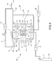
- the present invention further relates to an assembly that allows to implement one of the methods described above.
- an assembly 1 for densifying porous components according to the methodology known as Chemical Vapor Infiltration, comprises:
- said crucible 3 is positioned inside said furnace 12; and wherein said assembly 1 further comprises a vacuum pump 22 able to create a pressure between 0.1 kPa inside said crucible 3;
- said crucible 3 is of a material able to be exposed externally to an oxidizing atmosphere; and wherein said crucible 3 is made of material having thermal conductivity above 30 W/mK from ambient temperature to 1000° C.
- an assembly 1 for densifying porous components according to the methodology known as Chemical Vapor Infiltration, comprising:
- said crucible 3 is positioned inside said furnace 12.
- said assembly 1 further comprises a vacuum pump 22 able to create a pressure between 0.1 kPa and 25 KPa inside said crucible.
- said crucible 3 is of a material able to be exposed externally to an oxidizing atmosphere.
- said furnace 12 delimits an internal chamber to the furnace 12 that laps said crucible 3 and placed at an atmospheric pressure of approximately 90KPa.
- said assembly 1 further comprises a vacuum pump 22 able to create a pressure between 0.1 KPa and 25 KPa inside said crucible so that, at steady state, a reducing environment is formed inside said crucible 3.
- said crucible 3 is able to be exposed externally to an atmospheric pressure of approximately 90 KPa.
- said open container 15 delimits an inner loading chamber 16 able to receive at least a disk braking rotor 1 of a disk brake to be densified, preferably a plurality of rotors 1 of disk for disk brake to be densified.
- said assembly 1 further comprises a furnace 12 of the type for oxides 12 able to operate internally at ambient pressure and temperatures suitable for the CVI process.
- said crucible 3 is of graphite.
- said crucible 3 is externally jacketed with oxide-resistant coating.
- said coating comprises engobbio ® or engobe.
- said chamber external to the crucible 12 or chamber internal to the furnace 12 is an oxidizing environment, wherein said external environment laps upon said crucible 3.
- said crucible 3 comprises an open container 15 and a lid 17 able to close said open container 15 in a gas-tight manner.
- said open container 15 delimits an inner loading chamber 16 able to receive at least one porous component 1, preferably a plurality of porous components 1.
- said open container 14 comprises container support surfaces 16 wherein said container support surfaces 16 are ground and lapped.
- said crucible lid 17 comprises lid support surfaces 18 for setting the lid 17 on the open container 14, wherein said lid support surfaces 18 are ground and lapped.
- said lid support surfaces 18, with the crucible 3 closed are set on said container support surfaces 16 closing said crucible 3 in a gas-tight manner.
- said lid support surfaces 18, with the crucible 3 closed are set on said container support surfaces 16 closing said crucible 19 in a gas-tight manner interposing a sealing gasket 19.
- said crucible 3 is of a material able to have externally an atmospheric pressure of approximately 90 KPa.
- said assembly 1 further comprises a furnace 12 of the type for oxides 12 able to operate internally at ambient pressure and temperatures suitable for the CVI process.
- said crucible 3 is externally jacketed with oxide-resistant coating.
- said outer coating of the crucible 3 comprises engobbio® or engobe.
- said coating is made of material comprising metals, for example refractory steels.
- the chamber external to the crucible 12 or chamber internal to the furnace 12 is an oxidizing environment, wherein said environment laps upon said crucible 3.
- said crucible comprises silicon carbide SiC.
- said crucible (3) comprises silicon-infiltrated silicon carbide (Si-SiC); . and/or wherein
- said open container 14 comprises silicon carbide SiC.
- said crucible lid 17 comprises silicon carbide SiC.
- said crucible inlet 5 is provided in said open container 14.
- said crucible outlet 6 is provided in said crucible lid 17.
- said vacuum pump 21 is a nitrogen backflow pump able to maintain said exhaust gases 9 dry.
- said vacuum pump 21 is a screw pump NC 0100 B, NC 0200 B, NC 0300 B by messes Busch S.A., or a cryogenic pump, for example a NIKKISO cryogenic pump by Lewa GmbH.
- said vacuum pump 21 is able to bring said exhaust gases 9 to an ambient pressure downstream of said vacuum pump 21, or a limited overpressure able to convey said exhaust gases 9 to at least one burner 10.
- downstream of said vacuum pump 21 is provided an accumulation tank 50 of the exhaust gas 9.
- said tank comprises a device for separating tar and/or cyclic aromatic hydrocarbons 40; and said assembly 1 comprises a cooling device 51 for cooling the exhaust gases 9.
- said furnace for oxides 11 comprises resistance heating components 22, 42.
- said furnace 11 comprises inductance heating components.
- said furnace for oxides 11 comprises free flame heating components, for example burners 10 able to operate at ambient pressure.
- said furnace for oxides 11 comprises four burners 10.
- said assembly 1 comprises a recirculation conduit 23 that fluidically connects said vacuum pump 21 with said at least one burner 10.
- said recirculation conduit 23 comprises an inlet of fuel gas 24 for the entry into said conduit of a fuel gas 13 to be added to a burner exhaust gas.
- said furnace for oxides 11 comprises a combustion fume exhaust conduit 38.
- said assembly 20 comprises at least one tank or a circuit 39 for supplying gas suitable for densification, for example methane CH4, connected to said crucible inlet 5.
- gas suitable for densification for example methane CH4
- At least one tank or one circuit is provided for supplying technical service gas, for example nitrogen and/or argon or the like for washing the inner chamber of the crucible during the heating phases until the desired temperature of the crucible is reached.
- technical service gas for example nitrogen and/or argon or the like
- said assembly 20 comprises a device for separating tar and/or cyclic aromatic hydrocarbons 40 connected downstream of said crucible outlet 6.
- said assembly 20 comprises an exhaust gas conduit 41 connected downstream of said vacuum pump 21.
- said gas suitable for densification 4 is methane gas, or butane, or ethane, or propane or a combination of at least two thereof.
- said assembly 1 comprises a carrousel device 25 that comprises a closed path continuous movement device 26 that supports at least two crucibles 3.
- a closed path continuous movement device 26 comprises a loading segment 27 suitable for loading at least one porous component 1 in said crucible 3 when open.
- a closed path continuous movement device 26 comprises an unloading segment 28 suitable for unloading at least one densified component 2 from said crucible 3 when open.
- a closed path continuous movement device 26 comprises a treatment segment 29 associated with a continuous furnace 30 of the continuous furnace for oxides type, for example a tunnel kiln by Riedhammer.
- said continuous furnace 30 allows the entry of the at least two crucibles 3 and their exit.
- said carrousel device 25 comprises a movable feeding device 31 connected removably to at least one of the at least two crucibles 3 for feeding said densifying gas 4; and said carrousel device 25 comprises a movable evacuation device 32 for evacuating the exhaust gas 9 from at least one crucible 3 and placing the crucible 3 in a vacuum bringing the pressure of the crucible between 1 KPa and 15 KPa.
- said crucible inlet 5 comprises a quick-fitting crucible inlet valve 33 for selectively connecting and disconnecting said movable feeding device 31 for feeding the densifying gas 4; and said crucible outlet 6 comprises a quick-fitting crucible outlet valve 34 for selectively connecting and disconnecting said movable evacuation device 32 for the evacuation of said exhaust gas 9 and creating vacuum in the crucible 3.
- said closed path continuous movement device 26 comprises a porous component loading station 35 for loading at least one porous component 1 in said crucible 3.
- said closed path continuous movement device 26 comprises a densified component unloading station 36 for unloading at least one densified component 2 from said crucible 3.
- a system for example a system useful for testing, comprises a crucible or reactor chamber of silicon carbide or SiC.
- the material used is silicon-infiltrated silicon carbide.
- the chamber consists of two parts, the main container and the lid.
- the structure is cylindrical with dimensions of the part useful for loading the preforms of 400 mm in diameter and 335 mm in height.
- the thickness of the walls is 8 mm.
- the two parts are in contact through a lapped flange on a surface of 700 cm2 that allows to obtain the vacuum tightness.
- the chamber was constructed according to our design.
- the furnace of a commercial type (for example for oxides), consists of a simple pit furnace that can work at a maximum temperature of 1320°C, has Kanthal® resistors and an electric power of 13.2 kW.
- the insulation is of alumina-based oxide refractory.
- the cooling line is made of stainless steel within inner diameter 100 mm, jacketed and water-cooled. It is formed by 3 inclined segments for a total extension of approximately 10 meters. Along the line are inserted two pits for collecting the condensed hydrocarbons.
- the pumping group is formed by a double screw dry pump with maximum flow rate of 150 m3/h and maximum vacuum level of 0.5 mbar.
- the relevant parameters are the temperature in the holding phase of the process, the flow of methane, the level of partial pressure, the duration of the process, the geometry of the load.
- the ranges of the aforesaid variables that were explored are as follows:
- carbonized felt was used as the starting material.
- the felt in the form of a roll with a height of 300 mm, was wound to form a cylinder of such diameter as to occupy the entire useful space of the reaction chamber.
- the flow of the gas then took place entirely through the mass of the material to be densified.
- a maximum weight increase by 17.5% in one hour and by 34.5% in two hours was obtained.
- the deposit was morphologically uneven and the fibers did not appear to be homogeneously coated by the CVI carbon.
Landscapes
- Chemical & Material Sciences (AREA)
- Engineering & Computer Science (AREA)
- Ceramic Engineering (AREA)
- Materials Engineering (AREA)
- Organic Chemistry (AREA)
- Chemical Kinetics & Catalysis (AREA)
- Structural Engineering (AREA)
- Mechanical Engineering (AREA)
- Metallurgy (AREA)
- General Chemical & Material Sciences (AREA)
- Composite Materials (AREA)
- Manufacturing & Machinery (AREA)
- Inorganic Chemistry (AREA)
- Chemical Vapour Deposition (AREA)
- Physical Or Chemical Processes And Apparatus (AREA)
Priority Applications (5)
| Application Number | Priority Date | Filing Date | Title |
|---|---|---|---|
| EP18203800.0A EP3647459A1 (fr) | 2018-10-31 | 2018-10-31 | Procédé et ensemble par infiltration chimique en phase vapeur de composants poreux |
| EP19805395.1A EP3874074B1 (fr) | 2018-10-31 | 2019-10-30 | Procédé et ensemble par infiltration chimique en phase vapeur de composants poreux |
| US17/290,503 US11981607B2 (en) | 2018-10-31 | 2019-10-30 | Method and assembly for infiltration and rapid phase deposition of porous components |
| PCT/IB2019/059291 WO2020089803A1 (fr) | 2018-10-31 | 2019-10-30 | Procédé et ensemble pour l'infiltration et le dépôt en phase rapide de composants poreux |
| CN201980087464.1A CN113272470A (zh) | 2018-10-31 | 2019-10-30 | 用于渗透和快速气相沉积多孔组件的方法和装配件 |
Applications Claiming Priority (1)
| Application Number | Priority Date | Filing Date | Title |
|---|---|---|---|
| EP18203800.0A EP3647459A1 (fr) | 2018-10-31 | 2018-10-31 | Procédé et ensemble par infiltration chimique en phase vapeur de composants poreux |
Publications (1)
| Publication Number | Publication Date |
|---|---|
| EP3647459A1 true EP3647459A1 (fr) | 2020-05-06 |
Family
ID=64426628
Family Applications (2)
| Application Number | Title | Priority Date | Filing Date |
|---|---|---|---|
| EP18203800.0A Withdrawn EP3647459A1 (fr) | 2018-10-31 | 2018-10-31 | Procédé et ensemble par infiltration chimique en phase vapeur de composants poreux |
| EP19805395.1A Active EP3874074B1 (fr) | 2018-10-31 | 2019-10-30 | Procédé et ensemble par infiltration chimique en phase vapeur de composants poreux |
Family Applications After (1)
| Application Number | Title | Priority Date | Filing Date |
|---|---|---|---|
| EP19805395.1A Active EP3874074B1 (fr) | 2018-10-31 | 2019-10-30 | Procédé et ensemble par infiltration chimique en phase vapeur de composants poreux |
Country Status (4)
| Country | Link |
|---|---|
| US (1) | US11981607B2 (fr) |
| EP (2) | EP3647459A1 (fr) |
| CN (1) | CN113272470A (fr) |
| WO (1) | WO2020089803A1 (fr) |
Cited By (2)
| Publication number | Priority date | Publication date | Assignee | Title |
|---|---|---|---|---|
| IT202100023708A1 (it) * | 2021-09-14 | 2023-03-14 | Idrogena S R L | Impianto e procedimento per la produzione di idrogeno da scissione di molecole di metano |
| CN115784762A (zh) * | 2022-12-29 | 2023-03-14 | 上饶中昱新材料科技有限公司 | 一种碳碳热场材料的沉积方法及沉积设备 |
Families Citing this family (2)
| Publication number | Priority date | Publication date | Assignee | Title |
|---|---|---|---|---|
| FR3128956B1 (fr) * | 2021-11-10 | 2023-11-03 | Safran Ceram | Procédé de densification par infiltration chimique en phase vapeur |
| CN115636685B (zh) * | 2022-10-27 | 2023-08-15 | 上饶中昱新材料科技有限公司 | 一种cvi系统多料柱短周期制备大型筒状碳碳热场材料的方法和系统 |
Citations (42)
| Publication number | Priority date | Publication date | Assignee | Title |
|---|---|---|---|---|
| US3925577A (en) | 1972-11-24 | 1975-12-09 | Westinghouse Electric Corp | Silicon carbide coated graphite members and process for producing the same |
| FR2401888A1 (fr) | 1977-09-06 | 1979-03-30 | Europ Propulsion | Piece poreuse carbonee densifiee in situ par depot chimique en phase vapeur de materiaux refractaires autres que le carbone et procede de fabrication |
| US4824711A (en) | 1987-01-29 | 1989-04-25 | The United States Of America As Represented By The United States National Aeronautics And Space Administration | Ceramic honeycomb structures and method thereof |
| US5024878A (en) | 1988-09-14 | 1991-06-18 | Societe Europeenne De Propulsion | Composite material with zirconia matrix |
| EP0499004A1 (fr) | 1991-02-15 | 1992-08-19 | L'air Liquide, Societe Anonyme Pour L'etude Et L'exploitation Des Procedes Georges Claude | Procédé de production de matériau céramique à renfort de fibres |
| US5238710A (en) | 1992-03-30 | 1993-08-24 | Technology Assessment & Transfer, Inc. | Microwave energy-assisted chemical vapor infiltration |
| US5254374A (en) | 1992-04-08 | 1993-10-19 | The United States Of America As Represented By The United States Department Of Energy | Chemical vapor infiltration using microwave energy |
| US5332597A (en) | 1992-01-02 | 1994-07-26 | Air Products And Chemicals, Inc. | Method for manufacturing inorganic membranes by organometallic chemical vapor infiltration |
| US5389400A (en) | 1993-04-07 | 1995-02-14 | Applied Sciences, Inc. | Method for making a diamond/carbon/carbon composite useful as an integral dielectric heat sink |
| US5480678A (en) | 1994-11-16 | 1996-01-02 | The B. F. Goodrich Company | Apparatus for use with CVI/CVD processes |
| WO1996016000A1 (fr) | 1994-11-18 | 1996-05-30 | Du Pont Lanxide Composites Inc. | Structures ceramiques resistant au choc thermique a haute temperature |
| WO1996033295A1 (fr) | 1995-04-18 | 1996-10-24 | Societe Europeenne De Propulsion | Procede d'infiltration chimique en phase vapeur pour la densification de substrats poreux disposes en piles annulaires |
| US5580678A (en) | 1992-11-27 | 1996-12-03 | Gould Electronics Inc. | Adhesive sealed solid electrolyte cell housed within a ceramic frame and the method for producing it |
| US5738908A (en) | 1993-12-16 | 1998-04-14 | Societe Europeenne De Propulsion | Method of densifying porous substrates by chemical vapor infiltration of silicon carbide |
| CA2268729A1 (fr) | 1996-10-18 | 1998-04-30 | Societe Nationale D'etude Et De Construction De Moteurs D'aviation | Densification de substrats poreux disposes en piles annulaires par infiltration chimique en phase vapeur a gradient de temperature |
| US5916633A (en) | 1995-05-19 | 1999-06-29 | Georgia Tech Research Corporation | Fabrication of carbon/carbon composites by forced flow-thermal gradient chemical vapor infiltration |
| US6068930A (en) | 1995-12-14 | 2000-05-30 | Societe Nationale D'etude Et De Construction De Moteurs D'aviation | High-temperature composite materials with carbon or carbon-coated fibre reinforcements and enhanced oxidation resistance |
| US6083560A (en) | 1995-11-16 | 2000-07-04 | Alliant Techsystems Inc | Process for controlled deposition profile forced flow chemical vapor infiltration |
| US6187379B1 (en) | 1996-04-12 | 2001-02-13 | Georgia Tech Research Corporation | Fluidized bed coating process with liquid reagent |
| US6197374B1 (en) | 1996-11-08 | 2001-03-06 | Sintec Keramik Gmbh & Co Kg | Method for chemical vapor infiltration of refractory substances, especially carbon and silicon carbide |
| US6410086B1 (en) | 1999-11-26 | 2002-06-25 | Cerel (Ceramic Technologies) Ltd. | Method for forming high performance surface coatings and compositions of same |
| US20040115348A1 (en) | 2002-12-12 | 2004-06-17 | Landini Dennis James | Method for processing silicon-carbide preforms having a high temperature boron nitride coating |
| US20050238564A1 (en) | 2004-04-27 | 2005-10-27 | Walker Terence B | Method of removing tar-forming gases from CVD/CVI furnace effluent |
| US20070054103A1 (en) | 2005-09-07 | 2007-03-08 | General Electric Company | Methods and apparatus for forming a composite protection layer |
| US20080143005A1 (en) | 2004-05-28 | 2008-06-19 | Dacc Co., Ltd. | Method of Producing Carbon Fiber Reinforced Ceramic Matrix Composites |
| EP2058841A2 (fr) | 2007-11-07 | 2009-05-13 | Deutsches Zentrum für Luft- und Raumfahrt e.V. | Elément de transfert de chaleur et dispositif pour le traitement thermique de substrats |
| US20100296621A1 (en) | 2006-12-12 | 2010-11-25 | Commissariat A L'energie Atomique | Method of manufacturing nuclear fuel elements and a container for implementing such a method |
| US8105649B1 (en) | 2007-08-09 | 2012-01-31 | Imaging Systems Technology | Fabrication of silicon carbide shell |
| US8163088B2 (en) | 2005-02-17 | 2012-04-24 | Snecma Propulsion Solide | Method of densifying thin porous substrates by chemical vapor infiltration, and a loading device for such substrates |
| US20120231157A1 (en) | 2009-11-20 | 2012-09-13 | Zhiyong Xie | Method and device for producing carbon paper |
| CN103288466A (zh) | 2013-03-08 | 2013-09-11 | 西北工业大学 | 原位自生碳纳米管改性硅碳氮陶瓷基复合材料的制备方法 |
| US20130302616A1 (en) | 2012-05-10 | 2013-11-14 | Shin-Etsu Chemical Co., Ltd. | Method for coating a graphite material with pyrolytic boron nitride and a coated article obtained by that method |
| CN103744302A (zh) | 2013-11-27 | 2014-04-23 | 上海大学 | 一种基于平推流反应动力模型的等温化学气相渗透plc-ipc控制系统 |
| CN203561850U (zh) | 2013-11-27 | 2014-04-23 | 上海大学 | 一种基于平推流反应动力模型的等温化学气相渗透plc-ipc控制系统 |
| US20140272373A1 (en) | 2013-03-15 | 2014-09-18 | Rolls-Royce Corporation | Ceramic matrix composite and method and article of manufacture |
| US20140356534A1 (en) | 2012-01-10 | 2014-12-04 | Cvt Gmbh & Co. Kg | Method for the chemical vapor infiltration of refractive substances |
| KR101494237B1 (ko) | 2013-12-10 | 2015-02-17 | 김성재 | 탄소-탄소 복합재료를 제조하기 위한 혼성화학기상침투법 |
| CN104387113A (zh) | 2014-11-17 | 2015-03-04 | 苏州博清高新材料有限公司 | 一种纤维增强的陶瓷滤芯及其制备方法 |
| US20150152545A1 (en) | 2012-07-04 | 2015-06-04 | Herakles | A loader device and an installation for densifying stackable frustoconical porous preforms |
| US20150152547A1 (en) | 2012-08-17 | 2015-06-04 | Ihi Corporation | Method and apparatus for manufacturing heat-resistant composite material |
| US20160229758A1 (en) | 2015-02-11 | 2016-08-11 | United Technologies Corporation | Continuous chemical vapor deposition/infiltration coater |
| US20160305015A1 (en) | 2014-02-17 | 2016-10-20 | Ihi Corporation | Heat-resistant composite material production method and production device |
Family Cites Families (5)
| Publication number | Priority date | Publication date | Assignee | Title |
|---|---|---|---|---|
| EP0063924B2 (fr) * | 1981-04-28 | 1990-03-14 | Kawasaki Steel Corporation | Procédé et appareil de fusion et d'affinage d'un minerai finement divisé contenant des oxydes métalliques |
| EP1256973B1 (fr) * | 2001-04-12 | 2004-12-29 | Infineon Technologies SC300 GmbH & Co. KG | Système de chauffage et procédé pour chauffer un réacteur |
| FR2825699A1 (fr) * | 2001-06-12 | 2002-12-13 | Eads Launch Vehicles | Procede de densification et de traitement anticorrosion d'un materiau composite thermostructural |
| US9328417B2 (en) * | 2008-11-01 | 2016-05-03 | Ultratech, Inc. | System and method for thin film deposition |
| KR20110015780A (ko) * | 2009-08-10 | 2011-02-17 | 안요환 | 유골의 결정화 장치 |
-
2018
- 2018-10-31 EP EP18203800.0A patent/EP3647459A1/fr not_active Withdrawn
-
2019
- 2019-10-30 EP EP19805395.1A patent/EP3874074B1/fr active Active
- 2019-10-30 CN CN201980087464.1A patent/CN113272470A/zh active Pending
- 2019-10-30 WO PCT/IB2019/059291 patent/WO2020089803A1/fr not_active Ceased
- 2019-10-30 US US17/290,503 patent/US11981607B2/en active Active
Patent Citations (43)
| Publication number | Priority date | Publication date | Assignee | Title |
|---|---|---|---|---|
| US3925577A (en) | 1972-11-24 | 1975-12-09 | Westinghouse Electric Corp | Silicon carbide coated graphite members and process for producing the same |
| FR2401888A1 (fr) | 1977-09-06 | 1979-03-30 | Europ Propulsion | Piece poreuse carbonee densifiee in situ par depot chimique en phase vapeur de materiaux refractaires autres que le carbone et procede de fabrication |
| US4824711A (en) | 1987-01-29 | 1989-04-25 | The United States Of America As Represented By The United States National Aeronautics And Space Administration | Ceramic honeycomb structures and method thereof |
| US5024878A (en) | 1988-09-14 | 1991-06-18 | Societe Europeenne De Propulsion | Composite material with zirconia matrix |
| EP0499004A1 (fr) | 1991-02-15 | 1992-08-19 | L'air Liquide, Societe Anonyme Pour L'etude Et L'exploitation Des Procedes Georges Claude | Procédé de production de matériau céramique à renfort de fibres |
| US5332597A (en) | 1992-01-02 | 1994-07-26 | Air Products And Chemicals, Inc. | Method for manufacturing inorganic membranes by organometallic chemical vapor infiltration |
| US5238710A (en) | 1992-03-30 | 1993-08-24 | Technology Assessment & Transfer, Inc. | Microwave energy-assisted chemical vapor infiltration |
| US5254374A (en) | 1992-04-08 | 1993-10-19 | The United States Of America As Represented By The United States Department Of Energy | Chemical vapor infiltration using microwave energy |
| US5580678A (en) | 1992-11-27 | 1996-12-03 | Gould Electronics Inc. | Adhesive sealed solid electrolyte cell housed within a ceramic frame and the method for producing it |
| US5389400A (en) | 1993-04-07 | 1995-02-14 | Applied Sciences, Inc. | Method for making a diamond/carbon/carbon composite useful as an integral dielectric heat sink |
| US5738908A (en) | 1993-12-16 | 1998-04-14 | Societe Europeenne De Propulsion | Method of densifying porous substrates by chemical vapor infiltration of silicon carbide |
| US5480678A (en) | 1994-11-16 | 1996-01-02 | The B. F. Goodrich Company | Apparatus for use with CVI/CVD processes |
| WO1996016000A1 (fr) | 1994-11-18 | 1996-05-30 | Du Pont Lanxide Composites Inc. | Structures ceramiques resistant au choc thermique a haute temperature |
| WO1996033295A1 (fr) | 1995-04-18 | 1996-10-24 | Societe Europeenne De Propulsion | Procede d'infiltration chimique en phase vapeur pour la densification de substrats poreux disposes en piles annulaires |
| US5916633A (en) | 1995-05-19 | 1999-06-29 | Georgia Tech Research Corporation | Fabrication of carbon/carbon composites by forced flow-thermal gradient chemical vapor infiltration |
| US6083560A (en) | 1995-11-16 | 2000-07-04 | Alliant Techsystems Inc | Process for controlled deposition profile forced flow chemical vapor infiltration |
| US6068930A (en) | 1995-12-14 | 2000-05-30 | Societe Nationale D'etude Et De Construction De Moteurs D'aviation | High-temperature composite materials with carbon or carbon-coated fibre reinforcements and enhanced oxidation resistance |
| US6187379B1 (en) | 1996-04-12 | 2001-02-13 | Georgia Tech Research Corporation | Fluidized bed coating process with liquid reagent |
| CA2268729A1 (fr) | 1996-10-18 | 1998-04-30 | Societe Nationale D'etude Et De Construction De Moteurs D'aviation | Densification de substrats poreux disposes en piles annulaires par infiltration chimique en phase vapeur a gradient de temperature |
| US6197374B1 (en) | 1996-11-08 | 2001-03-06 | Sintec Keramik Gmbh & Co Kg | Method for chemical vapor infiltration of refractory substances, especially carbon and silicon carbide |
| US6410086B1 (en) | 1999-11-26 | 2002-06-25 | Cerel (Ceramic Technologies) Ltd. | Method for forming high performance surface coatings and compositions of same |
| US20040115348A1 (en) | 2002-12-12 | 2004-06-17 | Landini Dennis James | Method for processing silicon-carbide preforms having a high temperature boron nitride coating |
| US20050238564A1 (en) | 2004-04-27 | 2005-10-27 | Walker Terence B | Method of removing tar-forming gases from CVD/CVI furnace effluent |
| US20080143005A1 (en) | 2004-05-28 | 2008-06-19 | Dacc Co., Ltd. | Method of Producing Carbon Fiber Reinforced Ceramic Matrix Composites |
| US8163088B2 (en) | 2005-02-17 | 2012-04-24 | Snecma Propulsion Solide | Method of densifying thin porous substrates by chemical vapor infiltration, and a loading device for such substrates |
| US8491963B2 (en) | 2005-02-17 | 2013-07-23 | Snecma Propulsion Solide | Method of densifying thin porous substrates by chemical vapor infiltration, and a loading device for such substrates |
| US20070054103A1 (en) | 2005-09-07 | 2007-03-08 | General Electric Company | Methods and apparatus for forming a composite protection layer |
| US20100296621A1 (en) | 2006-12-12 | 2010-11-25 | Commissariat A L'energie Atomique | Method of manufacturing nuclear fuel elements and a container for implementing such a method |
| US8105649B1 (en) | 2007-08-09 | 2012-01-31 | Imaging Systems Technology | Fabrication of silicon carbide shell |
| EP2058841A2 (fr) | 2007-11-07 | 2009-05-13 | Deutsches Zentrum für Luft- und Raumfahrt e.V. | Elément de transfert de chaleur et dispositif pour le traitement thermique de substrats |
| US20120231157A1 (en) | 2009-11-20 | 2012-09-13 | Zhiyong Xie | Method and device for producing carbon paper |
| US20140356534A1 (en) | 2012-01-10 | 2014-12-04 | Cvt Gmbh & Co. Kg | Method for the chemical vapor infiltration of refractive substances |
| US20130302616A1 (en) | 2012-05-10 | 2013-11-14 | Shin-Etsu Chemical Co., Ltd. | Method for coating a graphite material with pyrolytic boron nitride and a coated article obtained by that method |
| US20150152545A1 (en) | 2012-07-04 | 2015-06-04 | Herakles | A loader device and an installation for densifying stackable frustoconical porous preforms |
| US20150152547A1 (en) | 2012-08-17 | 2015-06-04 | Ihi Corporation | Method and apparatus for manufacturing heat-resistant composite material |
| CN103288466A (zh) | 2013-03-08 | 2013-09-11 | 西北工业大学 | 原位自生碳纳米管改性硅碳氮陶瓷基复合材料的制备方法 |
| US20140272373A1 (en) | 2013-03-15 | 2014-09-18 | Rolls-Royce Corporation | Ceramic matrix composite and method and article of manufacture |
| CN103744302A (zh) | 2013-11-27 | 2014-04-23 | 上海大学 | 一种基于平推流反应动力模型的等温化学气相渗透plc-ipc控制系统 |
| CN203561850U (zh) | 2013-11-27 | 2014-04-23 | 上海大学 | 一种基于平推流反应动力模型的等温化学气相渗透plc-ipc控制系统 |
| KR101494237B1 (ko) | 2013-12-10 | 2015-02-17 | 김성재 | 탄소-탄소 복합재료를 제조하기 위한 혼성화학기상침투법 |
| US20160305015A1 (en) | 2014-02-17 | 2016-10-20 | Ihi Corporation | Heat-resistant composite material production method and production device |
| CN104387113A (zh) | 2014-11-17 | 2015-03-04 | 苏州博清高新材料有限公司 | 一种纤维增强的陶瓷滤芯及其制备方法 |
| US20160229758A1 (en) | 2015-02-11 | 2016-08-11 | United Technologies Corporation | Continuous chemical vapor deposition/infiltration coater |
Cited By (4)
| Publication number | Priority date | Publication date | Assignee | Title |
|---|---|---|---|---|
| IT202100023708A1 (it) * | 2021-09-14 | 2023-03-14 | Idrogena S R L | Impianto e procedimento per la produzione di idrogeno da scissione di molecole di metano |
| WO2023042053A1 (fr) * | 2021-09-14 | 2023-03-23 | Idrogena Srl | Installation et procédé de production d'hydrogène par scission de molécules de méthane |
| CN115784762A (zh) * | 2022-12-29 | 2023-03-14 | 上饶中昱新材料科技有限公司 | 一种碳碳热场材料的沉积方法及沉积设备 |
| CN115784762B (zh) * | 2022-12-29 | 2023-11-03 | 上饶中昱新材料科技有限公司 | 一种碳碳热场材料的沉积方法及沉积设备 |
Also Published As
| Publication number | Publication date |
|---|---|
| WO2020089803A1 (fr) | 2020-05-07 |
| EP3874074A1 (fr) | 2021-09-08 |
| US11981607B2 (en) | 2024-05-14 |
| CN113272470A (zh) | 2021-08-17 |
| EP3874074B1 (fr) | 2022-10-05 |
| US20210380493A1 (en) | 2021-12-09 |
Similar Documents
| Publication | Publication Date | Title |
|---|---|---|
| US11981607B2 (en) | Method and assembly for infiltration and rapid phase deposition of porous components | |
| US6953605B2 (en) | Method for densifying porous substrates by chemical vapour infiltration with preheated gas | |
| US10233540B2 (en) | Device for loading porous substrates of three-dimensional shape in order to be densified by directed flow chemical vapor infiltration | |
| US5738908A (en) | Method of densifying porous substrates by chemical vapor infiltration of silicon carbide | |
| CA2268729A1 (fr) | Densification de substrats poreux disposes en piles annulaires par infiltration chimique en phase vapeur a gradient de temperature | |
| CN115943054A (zh) | 密封炉 | |
| CN1325694C (zh) | 用化学气相渗透对碳纤维高温热处理和增密的方法和装置 | |
| CN108061462A (zh) | 一种烧结装置 | |
| US7410630B2 (en) | Method and an installation for obtaining carbon bodies from carbon-precursor bodies | |
| CN101395298B (zh) | 致密化多孔制品的方法 | |
| CN117125991A (zh) | 一种混合一体式制备硼化物超高温陶瓷涂层的方法 | |
| CN112567067A (zh) | 通过化学气相渗透使多孔环形衬底致密化的方法 | |
| US12264394B1 (en) | Chemical vapor infiltration densification method using single-pile plates for a semi-forced flow | |
| IT201800009953A1 (it) | Metodo ed un assieme di infiltrazione e la deposizione rapida da fase vapore di componenti porosi | |
| US12313140B2 (en) | Tooling of multi-pile plates for semi-forced flow | |
| AU2022348830A1 (en) | Hybrid process and hybrid device for low-co2 or for co2-free high-temperature technologies for the thermal treatment or production of inorganic materials | |
| Stinton et al. | Fiber-reinforced composites for gas turbine applications | |
| CN118591655A (zh) | 用于制造复合摩擦部件的热化学处理设备和方法 | |
| Waitz et al. | Resistance heated furnaces for protective gas and vacuum operation | |
| Lee et al. | Comparative Study of Thermal Shock Behavior with Fabrication Method of SiCf/SiC Composite |
Legal Events
| Date | Code | Title | Description |
|---|---|---|---|
| PUAI | Public reference made under article 153(3) epc to a published international application that has entered the european phase |
Free format text: ORIGINAL CODE: 0009012 |
|
| STAA | Information on the status of an ep patent application or granted ep patent |
Free format text: STATUS: THE APPLICATION HAS BEEN PUBLISHED |
|
| AK | Designated contracting states |
Kind code of ref document: A1 Designated state(s): AL AT BE BG CH CY CZ DE DK EE ES FI FR GB GR HR HU IE IS IT LI LT LU LV MC MK MT NL NO PL PT RO RS SE SI SK SM TR |
|
| AX | Request for extension of the european patent |
Extension state: BA ME |
|
| STAA | Information on the status of an ep patent application or granted ep patent |
Free format text: STATUS: THE APPLICATION IS DEEMED TO BE WITHDRAWN |
|
| 18D | Application deemed to be withdrawn |
Effective date: 20201107 |