EP2060184A1 - Procédé de cuisson d'aliments et appareil de cuisson correspondant - Google Patents
Procédé de cuisson d'aliments et appareil de cuisson correspondant Download PDFInfo
- Publication number
- EP2060184A1 EP2060184A1 EP20080168836 EP08168836A EP2060184A1 EP 2060184 A1 EP2060184 A1 EP 2060184A1 EP 20080168836 EP20080168836 EP 20080168836 EP 08168836 A EP08168836 A EP 08168836A EP 2060184 A1 EP2060184 A1 EP 2060184A1
- Authority
- EP
- European Patent Office
- Prior art keywords
- cooking
- steam
- insert
- volume
- cooking chamber
- Prior art date
- Legal status (The legal status is an assumption and is not a legal conclusion. Google has not performed a legal analysis and makes no representation as to the accuracy of the status listed.)
- Granted
Links
Images

Classifications
-
- A—HUMAN NECESSITIES
- A47—FURNITURE; DOMESTIC ARTICLES OR APPLIANCES; COFFEE MILLS; SPICE MILLS; SUCTION CLEANERS IN GENERAL
- A47J—KITCHEN EQUIPMENT; COFFEE MILLS; SPICE MILLS; APPARATUS FOR MAKING BEVERAGES
- A47J27/00—Cooking-vessels
- A47J27/04—Cooking-vessels for cooking food in steam; Devices for extracting fruit juice by means of steam ; Vacuum cooking vessels
-
- A—HUMAN NECESSITIES
- A21—BAKING; EDIBLE DOUGHS
- A21B—BAKERS' OVENS; MACHINES OR EQUIPMENT FOR BAKING
- A21B3/00—Parts or accessories of ovens
- A21B3/04—Air-treatment devices for ovens, e.g. regulating humidity
-
- A—HUMAN NECESSITIES
- A47—FURNITURE; DOMESTIC ARTICLES OR APPLIANCES; COFFEE MILLS; SPICE MILLS; SUCTION CLEANERS IN GENERAL
- A47J—KITCHEN EQUIPMENT; COFFEE MILLS; SPICE MILLS; APPARATUS FOR MAKING BEVERAGES
- A47J27/00—Cooking-vessels
- A47J27/14—Cooking-vessels for use in hotels, restaurants, or canteens
- A47J27/16—Cooking-vessels for use in hotels, restaurants, or canteens heated by steam
-
- F—MECHANICAL ENGINEERING; LIGHTING; HEATING; WEAPONS; BLASTING
- F24—HEATING; RANGES; VENTILATING
- F24C—DOMESTIC STOVES OR RANGES ; DETAILS OF DOMESTIC STOVES OR RANGES, OF GENERAL APPLICATION
- F24C15/00—Details
- F24C15/32—Arrangements of ducts for hot gases, e.g. in or around baking ovens
- F24C15/322—Arrangements of ducts for hot gases, e.g. in or around baking ovens with forced circulation
- F24C15/327—Arrangements of ducts for hot gases, e.g. in or around baking ovens with forced circulation with air moisturising
-
- F—MECHANICAL ENGINEERING; LIGHTING; HEATING; WEAPONS; BLASTING
- F24—HEATING; RANGES; VENTILATING
- F24C—DOMESTIC STOVES OR RANGES ; DETAILS OF DOMESTIC STOVES OR RANGES, OF GENERAL APPLICATION
- F24C15/00—Details
- F24C15/32—Arrangements of ducts for hot gases, e.g. in or around baking ovens
Definitions
- the invention relates to a method for cooking food with a cooking appliance with a cooking chamber and connected to this cooking chamber via a line steam generating space and the invention relates to a cooking appliance for this purpose.
- the EP 0 582 238 describes such a cooking appliance with a cooking chamber and a steam generating space, between which a partition wall is provided.
- the user wants cooking appliances in the large kitchen to have a corresponding heating output so that the required cooking processes run quickly. It should be possible to quickly heat up cold food in quick succession and even cook it. Although the state of the art converts the steam cooking, but is overwhelmed in the rapid batch change.
- the steam comes either from a separate store as superheated dry steam or from the heating register of the cooking apparatus itself, so that there is a loss of power with the withdrawal of steam.
- the present invention seeks to design a cooking appliance of the type mentioned, so that the cooking processes run faster, they should be designed just as gently.
- the steam of the separate steam generator can be initiated independently of the heating of the boiler in the cooking chamber.
- food can be quickly and gently regenerated, blanched and steamed even small quantities economically, without the cooking appliance itself and the heater must be heated in addition. Due to the high connected load and the small volume of the steam generator, operational readiness is reached within a very short time (2-3 minutes).
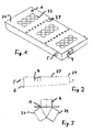
- the Fig. 1 shows a perspective view of an insert 1 for a cooking chamber 2 of a cooking appliance 3 according to an embodiment of the invention.
- the cooking appliance 3 with cooking chamber 2 is shown schematically in another embodiment in the Fig. 4 shown, where there is another insert 11 is inserted.
- the insert 1 can also be referred to as floor panel.
- He has an upper deck surface 21, which here has three groups of 2 times 4 holes 22.
- the three groups of holes, also called passage elements, subdivide the upper deck surface 21 into three shelves, wherein advantageously elements delimit the shelves from each other.
- these holes can be provided in a different number or arrangement, they also do not have to be round.
- the existing between the holes webs serve as a support for an ab routeden on the footprint Gargut disposer 8; such containers are for example grid baskets. It is advantageous, however, to arrange the holes centered on the shelves so that a closed area remains around these groups of holes, for example and advantageously in the range of 2 to 4 centimeters each.
- a steam supply manifold 4 is provided on one side of the insert 1, here the front side. This forms guide elements that distribute the steam.
- the steam supply manifold 4 is disposed near the top of the insert 1, so that steam is introduced just above or just in the water reservoir 13. This results in a lower pressure under the insert 1, 11 and this can be sealed against the upper cooking chamber volume more easily.
- Another advantage is that the energy distribution is not dependent on the height of the water mask 13. It can also be omitted or only during the cooking process by Form condensation.
- Side sliders 5 serve to position the insert 1 in the cooking chamber 2.
- Die Fig. 2 is a side view of the insert 1 after Fig. 1 ; It can be seen that the lateral lower edge 6 of the insert 1 extends obliquely in the transverse direction. These lower edges 6 are designed all around so that these lower edges 6 of the insert 1 either stand up on the bottom of the cooking chamber 2 or are held by elements such as the sliders 5 at a very small distance above the bottom of the cooking chamber 2.
- the Fig. 3 shows a schematic representation of the steam supply manifold 4 in the insert 1 after Fig. 1 , This may be configured rectangular in cross-section, or even round, adapted to the steam supply 14 of the cooking device 3 in the side wall of the cooking chamber 2.
- the steam supply manifold 4 is now constructed as a total of three-armed manifold, which divides the transverse inflowing steam into two streams and swirled.
- the angle of the arms 24 with respect to the axis of the incoming steam may, for example, be 60 degrees.
- the aim of the division is the better distribution of steam just below the first, the distributor 4 near footprint.
- the Fig. 4 shows a schematic side cutaway view of a cooking appliance 3 with insert 11 and showing the steam path 12.
- the cooking appliance 3 has a limited by the wall 10 cooking chamber 2, which is closed by a cover 7 becomes.
- a steam outlet and / or a pressure relief valve is provided in a known manner.
- the Associated Fig. 5 shows a schematic plan view of the device Fig. 4 , wherein it is apparent that only two groups of holes 22 are provided for two food containers 8 here.
- the insert 11 On the bottom of the cooking device 3 is the insert 11.
- the insert 11 is in a water mask 13.
- the water mask 13 seals, inter alia, the insert 11 against the surrounding soil, so that steam substantially only through the holes 22nd
- the feed consists of the steam supply manifold 4 of the insert and a steam supply 14 of the cooking appliance, which is fed directly, for example, from a steam storage directly or a steam generator directly from the introduction volume 42 into the cooking material volume 32.
- the inflow of steam or water is controlled via an interposed valve.
- the steam 12 flows through the cooking container 8 from bottom to top, that is from the holes 22 of the insert 1, 11 towards the lid 7. Due to the regular arrangement of the holes 22, the steam over the entire surface of the insert 1, which the cooking chamber. 2 facing, in the cooking chamber 2 and in the cooking container 8 to flow.
- This type of inflow into the cooking chamber 2 or the flow through the cooking container 8 is particularly advantageous because air, which is located at the beginning of a cooking process in the cooking container 8, can be efficiently displaced, and so a good and constant distribution of the steam in the cooking container 8 can be guaranteed. Due to the even distribution of the steam, the food can be heated evenly, which has a positive effect on the cooking quality of the food. Furthermore, the cooking time so shortened.
- the cooking chamber 2 of the cooking appliance 1 is pressure-resistant, for example up to 10 bar.
- the principle of operation of the cooking device 3 is as follows. It is preferably constructed a water mask 13 in the cooking chamber 2. Steam is generated by a separately heated, external or steam generator located in the cooking apparatus and injected into the cooking chamber 2 of the cooking apparatus as described below. The steam generator has a separate heating in the order of magnitude of the boiler heating. During the heating phase, maximum power is available.
- steam 11 dry saturated steam
- the pressure of the vapor accumulator can be, for example, 0.5-3 bar.
- the pressure in the antechamber 2 is then between 0.5 and 3 bar, preferably between 1 bar and 2 bar.
- the steam is designed in the saturated steam or in the dry steam range up to a maximum of 20 Kelvin above the saturated steam curve. Surface damage caused by dry steam on the food is thereby avoided and the steam is in the favorable for a discharge of heat energy to the cooking condensate.
- Another advantage of this design is that the steam does not have to be passed through a water master 13 for cooling. The transported in the steam energy is thus almost immediately without losses for the heating of the food 9 available.
- the steam is in the cooking device 3 below, near the bottom, just below the surface 21 of the insert 11.
- the steam is guided according to the indicated by the arrows 12 ways from bottom to top through the food 9 and thus also supports the initial venting of the Cooking chamber 2.
- the inlet comprises a self-closing check valve which is flush with the wall 10.
- the user fills food or food 9 in Gargut essenceer 8 and puts them in the cooking chamber 2 on the shelves.
- a heating phase is started, in which the saturated steam 12 is guided via the feed line 14 into the introduction volume 42 of the cooking chamber 2.
- the steam enters through the holes 22 according to the arrows 12 in the cooking material volume 32 and brushes past the food 9, which is acted upon by the correspondingly arranged Gargut anyer 8 directly from the steam 12.
- a heat transfer occurs and the food 9 is heated. Since the temperature of the steam due to the only slightly increased pressure is not much greater than 100 degrees Celsius, no burning of the food 9 can occur.
- the steam condenses on the cold food and heats it up very gently and very quickly.
- the quality of the cooking process can thereby be increased by the oxygen in the cooking chamber 2 is removed with the air.
- This can be easily achieved by a multi-function valve is used in the cooking chamber 2, which in addition to the safety function (overpressure) and the rapid release of the cooking overpressure mainly contains a flow valve and vacuum breaker.
- the heating starts air escapes from the cooking chamber 2.
- the flow rate of the escaping gas increases sharply. This quantity is measured and the valve is closed. That happens too a time when the originally existing amount of air has been greatly reduced and substantially steam in the cooking chamber 2 is present.
- the control of the cooking apparatus from the temperature profile / time behavior of the cooking chamber 2 determine the dependent of the amount and type of food 9 power requirement and control the steam supply accordingly. This can be done both via a proportional valve, as well as clocking a solenoid valve.
- a ventilation device is arranged on or in the region of the cover 7 of the cooking appliance 3, advantageously diametrically opposite the steam supply 14.
- the steam generator can have several outlets and so gradually supply several cooking appliances with steam.
- the adaptation to the different power levels is done simply via orifices.
- the heating of the cooking chamber 2 by a conventional heating coil independently of the steam generator is particularly advantageous.
- the connected load of the steam generator can be in the range of the connected load of the cooking appliance itself and thus the heating power be doubled.
- a great practice advantage results from the shortening of the cooking time achieved by 50% - 70%. Volumes of the steam generator of less than 25 liters allow a compact design.
Landscapes
- Engineering & Computer Science (AREA)
- Food Science & Technology (AREA)
- Life Sciences & Earth Sciences (AREA)
- Chemical & Material Sciences (AREA)
- Combustion & Propulsion (AREA)
- Mechanical Engineering (AREA)
- General Engineering & Computer Science (AREA)
- Commercial Cooking Devices (AREA)
- Cookers (AREA)
Applications Claiming Priority (1)
| Application Number | Priority Date | Filing Date | Title |
|---|---|---|---|
| CH01775/07A CH714211B1 (de) | 2007-11-16 | 2007-11-16 | Verfahren zum Garen von Kochgut und Kochgerät hierfür. |
Publications (2)
| Publication Number | Publication Date |
|---|---|
| EP2060184A1 true EP2060184A1 (fr) | 2009-05-20 |
| EP2060184B1 EP2060184B1 (fr) | 2016-08-31 |
Family
ID=39473230
Family Applications (1)
| Application Number | Title | Priority Date | Filing Date |
|---|---|---|---|
| EP08168836.8A Active EP2060184B1 (fr) | 2007-11-16 | 2008-11-11 | Procédé de cuisson d'aliments et appareil de cuisson correspondant |
Country Status (2)
| Country | Link |
|---|---|
| EP (1) | EP2060184B1 (fr) |
| CH (1) | CH714211B1 (fr) |
Cited By (4)
| Publication number | Priority date | Publication date | Assignee | Title |
|---|---|---|---|---|
| ITMO20090261A1 (it) * | 2009-10-23 | 2011-04-24 | Gilberto Cattaneo | Sistema perfezionato per il riscaldamento di pasta precotta od altri alimenti precotti utilizzabile preferibilmente, ma non esclusivamente nel settore delle imprese che preparano e servono alimenti e bevande (ristoranti, bar, caffe') |
| WO2015185283A1 (fr) * | 2014-06-06 | 2015-12-10 | Arcelik Anonim Sirketi | Dispositif de cuisson comprenant un accessoire de vapeur |
| CN113804842A (zh) * | 2021-09-23 | 2021-12-17 | 珠海格力电器股份有限公司 | 烹饪器具判熟装置、方法以及烹饪器具 |
| DE102020216520A1 (de) | 2020-12-22 | 2022-06-23 | BSH Hausgeräte GmbH | Haushalts-Dampfgargerät mit Überhitzermodul |
Citations (12)
| Publication number | Priority date | Publication date | Assignee | Title |
|---|---|---|---|---|
| DE887002C (de) * | 1951-07-29 | 1953-08-20 | Friedrich Schurig | Elektrisch beheiztes Viehfutterdaempffass |
| DE939528C (de) * | 1952-05-24 | 1956-02-23 | Hellmuth Dr Med Hulverscheidt | AErztlicher Instrumentensterilisator |
| GB1379370A (en) * | 1972-03-15 | 1975-01-02 | Electrolux Ab | Method of and apparatus for continuous cooking of food |
| DE3026312A1 (de) * | 1979-09-05 | 1981-03-12 | Robert Mauch Elro-Werke AG, Bremgarten | Druckkochapparat. |
| FR2638376A1 (fr) * | 1988-10-27 | 1990-05-04 | Lacan Jacques | Appareil generateur de buee pour la cuisson de produits alimentaires |
| EP0582238A1 (fr) | 1992-08-04 | 1994-02-09 | Wiesheu-Wiwa GmbH | Dispositif pour le traitement à chaud de produits alimentaires |
| WO2001080649A2 (fr) * | 2000-04-21 | 2001-11-01 | The Pillsbury Company | Four a jet d'air chaud avec injection de vapeur et procede pour la cuisson de produits de pate |
| JP2003250505A (ja) * | 2002-03-01 | 2003-09-09 | Kinrei:Kk | 冷凍食品の調理方法及び冷凍食品用解凍機 |
| JP2006102066A (ja) * | 2004-10-04 | 2006-04-20 | Osaka Gas Co Ltd | 加熱調理装置 |
| JP2006105523A (ja) * | 2004-10-07 | 2006-04-20 | Thermo Electron Kk | 過熱蒸気処理装置 |
| JP2006166797A (ja) * | 2004-12-16 | 2006-06-29 | Ryoso:Kk | 食品の処理方法と装置 |
| EP1729065A1 (fr) * | 2004-03-19 | 2006-12-06 | Sharp Kabushiki Kaisha | Appareil de cuisson a la vapeur |
Family Cites Families (4)
| Publication number | Priority date | Publication date | Assignee | Title |
|---|---|---|---|---|
| GB191307612A (en) * | 1913-03-31 | 1913-10-16 | Harold Wade | Improvements in or relating to a Device for Extracting Fruitjuice by Means of Steam. |
| US6125738A (en) * | 1999-10-13 | 2000-10-03 | Poister; Clarence E. | Cooking device for separating and retaining fat from foods during cooking |
| JP3979870B2 (ja) * | 2002-04-16 | 2007-09-19 | 株式会社田季野 | せいろ型弁当容器 |
| US6833534B2 (en) * | 2002-04-23 | 2004-12-21 | Cleveland Range | Method and steaming oven and collector plate |
-
2007
- 2007-11-16 CH CH01775/07A patent/CH714211B1/de unknown
-
2008
- 2008-11-11 EP EP08168836.8A patent/EP2060184B1/fr active Active
Patent Citations (12)
| Publication number | Priority date | Publication date | Assignee | Title |
|---|---|---|---|---|
| DE887002C (de) * | 1951-07-29 | 1953-08-20 | Friedrich Schurig | Elektrisch beheiztes Viehfutterdaempffass |
| DE939528C (de) * | 1952-05-24 | 1956-02-23 | Hellmuth Dr Med Hulverscheidt | AErztlicher Instrumentensterilisator |
| GB1379370A (en) * | 1972-03-15 | 1975-01-02 | Electrolux Ab | Method of and apparatus for continuous cooking of food |
| DE3026312A1 (de) * | 1979-09-05 | 1981-03-12 | Robert Mauch Elro-Werke AG, Bremgarten | Druckkochapparat. |
| FR2638376A1 (fr) * | 1988-10-27 | 1990-05-04 | Lacan Jacques | Appareil generateur de buee pour la cuisson de produits alimentaires |
| EP0582238A1 (fr) | 1992-08-04 | 1994-02-09 | Wiesheu-Wiwa GmbH | Dispositif pour le traitement à chaud de produits alimentaires |
| WO2001080649A2 (fr) * | 2000-04-21 | 2001-11-01 | The Pillsbury Company | Four a jet d'air chaud avec injection de vapeur et procede pour la cuisson de produits de pate |
| JP2003250505A (ja) * | 2002-03-01 | 2003-09-09 | Kinrei:Kk | 冷凍食品の調理方法及び冷凍食品用解凍機 |
| EP1729065A1 (fr) * | 2004-03-19 | 2006-12-06 | Sharp Kabushiki Kaisha | Appareil de cuisson a la vapeur |
| JP2006102066A (ja) * | 2004-10-04 | 2006-04-20 | Osaka Gas Co Ltd | 加熱調理装置 |
| JP2006105523A (ja) * | 2004-10-07 | 2006-04-20 | Thermo Electron Kk | 過熱蒸気処理装置 |
| JP2006166797A (ja) * | 2004-12-16 | 2006-06-29 | Ryoso:Kk | 食品の処理方法と装置 |
Cited By (6)
| Publication number | Priority date | Publication date | Assignee | Title |
|---|---|---|---|---|
| ITMO20090261A1 (it) * | 2009-10-23 | 2011-04-24 | Gilberto Cattaneo | Sistema perfezionato per il riscaldamento di pasta precotta od altri alimenti precotti utilizzabile preferibilmente, ma non esclusivamente nel settore delle imprese che preparano e servono alimenti e bevande (ristoranti, bar, caffe') |
| WO2011048577A3 (fr) * | 2009-10-23 | 2011-07-07 | Gilberto Cattaneo | Système amélioré pour le réchauffage de pâtes précuites ou autres aliments précuits utilisé préférablement, mais non exclusivement, dans des établissements préparant et servant plats et boissons (restaurants, bars, cafés) |
| WO2015185283A1 (fr) * | 2014-06-06 | 2015-12-10 | Arcelik Anonim Sirketi | Dispositif de cuisson comprenant un accessoire de vapeur |
| DE102020216520A1 (de) | 2020-12-22 | 2022-06-23 | BSH Hausgeräte GmbH | Haushalts-Dampfgargerät mit Überhitzermodul |
| WO2022135902A1 (fr) | 2020-12-22 | 2022-06-30 | BSH Hausgeräte GmbH | Appareil domestique de cuisson à la vapeur équipé d'un module de surchauffe |
| CN113804842A (zh) * | 2021-09-23 | 2021-12-17 | 珠海格力电器股份有限公司 | 烹饪器具判熟装置、方法以及烹饪器具 |
Also Published As
| Publication number | Publication date |
|---|---|
| CH714211B1 (de) | 2019-03-29 |
| EP2060184B1 (fr) | 2016-08-31 |
Similar Documents
| Publication | Publication Date | Title |
|---|---|---|
| EP2697569B1 (fr) | Appareil de cuisson à la vapeur, en particulier four à vapeur | |
| EP0092851A2 (fr) | Dispositif pour traiter des aliments | |
| DE1617987C3 (de) | Vorrichtung zum kontinuierlichen Sterilisieren von Produkten, insbesondere von in Behältern befindlichen Lebensmitteln | |
| DE1958885A1 (de) | Einrichtung zur Trocknung und UEberhitzung von Nassdampf in Atomkernkraftwerken | |
| EP2060184B1 (fr) | Procédé de cuisson d'aliments et appareil de cuisson correspondant | |
| DE2217836C3 (de) | Hochtemperaturdämpfer zum Dämpfen von textlien Warenbahnen | |
| EP0520565A1 (fr) | Procédé de contrôle de la puissance de cuisson continu | |
| EP3279570A1 (fr) | Évaporateur et cuiseur à vapeur comprenant un tel évaporateur | |
| EP2618071A2 (fr) | Accumulateur stratifié | |
| DE2229991C3 (de) | Dampfdruckkocher | |
| AT260801B (de) | Verfahren zur Trocknung kolloidaler Stoffe und Vorrichtungen zur Durchführung des Verfahrens | |
| EP3640537B1 (fr) | Dispositif évaporateur et appareil électrique doté d'un dispositif évaporateur | |
| EP3597080B1 (fr) | Dispositif et procédé de traitement des denrées alimentaires disposés dans un récipient | |
| CH642155A5 (de) | Dampferzeuger mit zwischenwand zwischen zwei brennkammern. | |
| DE102005058570B3 (de) | Verfahren zur Warmwasserbereitung mit einem Wärmeerzeuger und einem Schichtladespeicher | |
| EP1862734B1 (fr) | Générateur de vapeur | |
| DE912984C (de) | Verfahren zur Gewinnung von Heizdampf mittels eines Elektroden-Dampferzeugers | |
| DE102013223030B4 (de) | Backofen und Nachrüstsatz für Backöfen | |
| EP0954971A2 (fr) | Evacuation de la vapeur pour four de cuisson | |
| EP4372274B1 (fr) | Dispositif de production de vapeur et appareil ménager équipé d'un tel dispositif | |
| DE10220624A1 (de) | Gemischter Backofen mit hoher Leistung zum Backen mit Konvektion und/oder Dämpfen | |
| DE2111904A1 (de) | Vorrichtung mit Wassersumpf zum Daempfen von Textilware | |
| WO2013107603A1 (fr) | Appareil de cuisson et procédé pour faire fonctionner un appareil de cuisson | |
| DD225904A1 (de) | Verfahren und einrichtung zum garen unter druck | |
| DE1961296C3 (de) | Dampferzeuger |
Legal Events
| Date | Code | Title | Description |
|---|---|---|---|
| PUAI | Public reference made under article 153(3) epc to a published international application that has entered the european phase |
Free format text: ORIGINAL CODE: 0009012 |
|
| AK | Designated contracting states |
Kind code of ref document: A1 Designated state(s): AT BE BG CH CY CZ DE DK EE ES FI FR GB GR HR HU IE IS IT LI LT LU LV MC MT NL NO PL PT RO SE SI SK TR |
|
| AX | Request for extension of the european patent |
Extension state: AL BA MK RS |
|
| 17P | Request for examination filed |
Effective date: 20091113 |
|
| AKX | Designation fees paid |
Designated state(s): AT CH DE FR IT LI |
|
| 17Q | First examination report despatched |
Effective date: 20100111 |
|
| 17Q | First examination report despatched |
Effective date: 20100712 |
|
| GRAP | Despatch of communication of intention to grant a patent |
Free format text: ORIGINAL CODE: EPIDOSNIGR1 |
|
| INTG | Intention to grant announced |
Effective date: 20151014 |
|
| GRAP | Despatch of communication of intention to grant a patent |
Free format text: ORIGINAL CODE: EPIDOSNIGR1 |
|
| INTG | Intention to grant announced |
Effective date: 20160316 |
|
| GRAS | Grant fee paid |
Free format text: ORIGINAL CODE: EPIDOSNIGR3 |
|
| GRAA | (expected) grant |
Free format text: ORIGINAL CODE: 0009210 |
|
| AK | Designated contracting states |
Kind code of ref document: B1 Designated state(s): AT CH DE FR IT LI |
|
| REG | Reference to a national code |
Ref country code: CH Ref legal event code: EP |
|
| REG | Reference to a national code |
Ref country code: DE Ref legal event code: R096 Ref document number: 502008014572 Country of ref document: DE |
|
| REG | Reference to a national code |
Ref country code: AT Ref legal event code: REF Ref document number: 824116 Country of ref document: AT Kind code of ref document: T Effective date: 20161015 |
|
| REG | Reference to a national code |
Ref country code: CH Ref legal event code: NV Representative=s name: GEVERS SA, CH |
|
| REG | Reference to a national code |
Ref country code: DE Ref legal event code: R097 Ref document number: 502008014572 Country of ref document: DE |
|
| PG25 | Lapsed in a contracting state [announced via postgrant information from national office to epo] |
Ref country code: IT Free format text: LAPSE BECAUSE OF FAILURE TO SUBMIT A TRANSLATION OF THE DESCRIPTION OR TO PAY THE FEE WITHIN THE PRESCRIBED TIME-LIMIT Effective date: 20160831 |
|
| PLBE | No opposition filed within time limit |
Free format text: ORIGINAL CODE: 0009261 |
|
| STAA | Information on the status of an ep patent application or granted ep patent |
Free format text: STATUS: NO OPPOSITION FILED WITHIN TIME LIMIT |
|
| 26N | No opposition filed |
Effective date: 20170601 |
|
| REG | Reference to a national code |
Ref country code: FR Ref legal event code: ST Effective date: 20170731 |
|
| PG25 | Lapsed in a contracting state [announced via postgrant information from national office to epo] |
Ref country code: FR Free format text: LAPSE BECAUSE OF NON-PAYMENT OF DUE FEES Effective date: 20161130 |
|
| REG | Reference to a national code |
Ref country code: DE Ref legal event code: R081 Ref document number: 502008014572 Country of ref document: DE Owner name: ILLINOIS TOOL WORKS INC., GLENVIEW, US Free format text: FORMER OWNER: ELRO (HOLDING) AG, BREMGARTEN, CH |
|
| REG | Reference to a national code |
Ref country code: AT Ref legal event code: PC Ref document number: 824116 Country of ref document: AT Kind code of ref document: T Owner name: ILLINOIS TOOL WORKS INC., US Effective date: 20180731 |
|
| REG | Reference to a national code |
Ref country code: CH Ref legal event code: NV Representative=s name: BOVARD SA NEUCHATEL CONSEILS EN PROPRIETE INTE, CH |
|
| P01 | Opt-out of the competence of the unified patent court (upc) registered |
Effective date: 20230606 |
|
| REG | Reference to a national code |
Ref country code: CH Ref legal event code: U11 Free format text: ST27 STATUS EVENT CODE: U-0-0-U10-U11 (AS PROVIDED BY THE NATIONAL OFFICE) Effective date: 20251201 |
|
| PGFP | Annual fee paid to national office [announced via postgrant information from national office to epo] |
Ref country code: DE Payment date: 20251128 Year of fee payment: 18 |
|
| PGFP | Annual fee paid to national office [announced via postgrant information from national office to epo] |
Ref country code: AT Payment date: 20251128 Year of fee payment: 18 |
|
| PGFP | Annual fee paid to national office [announced via postgrant information from national office to epo] |
Ref country code: CH Payment date: 20251201 Year of fee payment: 18 |
|
| REG | Reference to a national code |
Ref country code: CH Ref legal event code: R18 Free format text: ST27 STATUS EVENT CODE: U-0-0-R10-R18 (AS PROVIDED BY THE NATIONAL OFFICE) Effective date: 20260209 |
|
| REG | Reference to a national code |
Ref country code: CH Ref legal event code: R18 Free format text: ST27 STATUS EVENT CODE: U-0-0-R10-R18 (AS PROVIDED BY THE NATIONAL OFFICE) Effective date: 20260320 |