EP2060385A2 - Faserwicklungsvorrichtung - Google Patents
Faserwicklungsvorrichtung Download PDFInfo
- Publication number
- EP2060385A2 EP2060385A2 EP08018513A EP08018513A EP2060385A2 EP 2060385 A2 EP2060385 A2 EP 2060385A2 EP 08018513 A EP08018513 A EP 08018513A EP 08018513 A EP08018513 A EP 08018513A EP 2060385 A2 EP2060385 A2 EP 2060385A2
- Authority
- EP
- European Patent Office
- Prior art keywords
- guide
- guide ring
- tube
- mandrel
- state
- Prior art date
- Legal status (The legal status is an assumption and is not a legal conclusion. Google has not performed a legal analysis and makes no representation as to the accuracy of the status listed.)
- Granted
Links
Images




Classifications
-
- B—PERFORMING OPERATIONS; TRANSPORTING
- B29—WORKING OF PLASTICS; WORKING OF SUBSTANCES IN A PLASTIC STATE IN GENERAL
- B29C—SHAPING OR JOINING OF PLASTICS; SHAPING OF MATERIAL IN A PLASTIC STATE, NOT OTHERWISE PROVIDED FOR; AFTER-TREATMENT OF THE SHAPED PRODUCTS, e.g. REPAIRING
- B29C53/00—Shaping by bending, folding, twisting, straightening or flattening; Apparatus therefor
- B29C53/80—Component parts, details or accessories; Auxiliary operations
- B29C53/8008—Component parts, details or accessories; Auxiliary operations specially adapted for winding and joining
- B29C53/8016—Storing, feeding or applying winding materials, e.g. reels, thread guides, tensioners
-
- B—PERFORMING OPERATIONS; TRANSPORTING
- B29—WORKING OF PLASTICS; WORKING OF SUBSTANCES IN A PLASTIC STATE IN GENERAL
- B29C—SHAPING OR JOINING OF PLASTICS; SHAPING OF MATERIAL IN A PLASTIC STATE, NOT OTHERWISE PROVIDED FOR; AFTER-TREATMENT OF THE SHAPED PRODUCTS, e.g. REPAIRING
- B29C53/00—Shaping by bending, folding, twisting, straightening or flattening; Apparatus therefor
- B29C53/56—Winding and joining, e.g. winding spirally
- B29C53/58—Winding and joining, e.g. winding spirally helically
- B29C53/60—Winding and joining, e.g. winding spirally helically using internal forming surfaces, e.g. mandrels
- B29C53/62—Winding and joining, e.g. winding spirally helically using internal forming surfaces, e.g. mandrels rotatable about the winding axis
- B29C53/64—Winding and joining, e.g. winding spirally helically using internal forming surfaces, e.g. mandrels rotatable about the winding axis and moving axially
-
- B—PERFORMING OPERATIONS; TRANSPORTING
- B29—WORKING OF PLASTICS; WORKING OF SUBSTANCES IN A PLASTIC STATE IN GENERAL
- B29C—SHAPING OR JOINING OF PLASTICS; SHAPING OF MATERIAL IN A PLASTIC STATE, NOT OTHERWISE PROVIDED FOR; AFTER-TREATMENT OF THE SHAPED PRODUCTS, e.g. REPAIRING
- B29C63/00—Lining or sheathing, i.e. applying preformed layers or sheathings of plastics; Apparatus therefor
- B29C63/24—Lining or sheathing, i.e. applying preformed layers or sheathings of plastics; Apparatus therefor using threads
Definitions
- the present invention relates to a filament winding apparatus equipped with a helical winding device.
- a fiber bundle applied with resin is hoop wound or helical wound around a mandrel to form a reinforcement layer (see Japanese Laid-Open Patent Publication No. 10-119138 (paragraph 0002, Fig. 3 )).
- a filament winding apparatus of a mode of guiding numerous fiber bundles with a plurality of helical winding rings, and simultaneously winding a group of fiber bundles around the mandrel is known in Japanese Laid-Open Patent Publication No. 2004-314550 (paragraph 0019, Fig. 1 ), for example.
- Japanese Laid-Open Patent Publication No. 2004-314550 paragraph 0019, Fig. 1
- two helical winding rings are adjacently arranged along an axis center of the mandrel, and the group of fiber bundles fed through each ring is wound around the mandrel.
- the winding process can be carried out in a shorter time, and the pressure container and the like can be efficiently manufactured by that much by simultaneously helical winding the group of fiber bundles around the mandrel in the above manner.
- the time necessary for the winding process can be reduced the greater the number of fiber bundles wound around the mandrel by helical winding.
- the fiber bundle having the same number as in a case where the winding angle is small may be wound at a large winding angle ignoring the appropriate number, but in this case, bumps are formed on the surface of a wound layer, disorder occurs in the winding of the fiber bundle, and the strength thereof lowers as a result. That is, wasteful consumption of the fiber bundle becomes inevitable.
- the number of fiber bundles to be wound around the mandrel needs to be changed between a case where the winding angle is large and a case where the winding angle is small, and great amount of trouble becomes necessary to change the arrangement when performing the helical winding while changing the winding angle of the fiber bundle.
- a filament winding apparatus of the present invention includes a helical winding device which winds a fiber bundle around a circumferential surface of a mandrel.
- the helical winding device includes a fixed frame arranged upstanding on a mount, and a helical winding head supported by the fixed frame.
- the helical winding head includes a plurality of guide rings adjacently arranged along an axis center of the mandrel and coupled in a relatively freely rotating manner in a circumferential direction, a group of guide tubes arranged at an equal interval along the circumferential direction of each guide ring, and a phase switching structure rotating a guide ring on a movable side.
- Each guide ring is configured to be switchable between a first state in which a phase position of the guide tube in each guide ring is matched and a second state in which the phase position of the guide tube at each guide ring is evenly shifted in the circumferential direction by the phase switching structure.
- a tube exit of the guide tube attached to each guide ring is arranged close along an axis center direction of the mandrel in the first state.
- one of the guide rings is fixed and supported at the fixed frame, and the other guide rings are coupled in a freely rotating manner in the circumferential direction with respect to the fixed and supported guide ring.
- the phase switching structure is configured by including an operator switching one of the guide rings that can be rotatably displaced, and a positioning structure arranged between the adjacent guide rings.
- the guide tube formed to a linear tubular form is attached and fixed to each guide ring.
- the guide tube attached to at least one guide ring is tilted so that the tube exits are arranged close.
- the helical winding head is configured by a plurality of guide rings adjacently coupled in a relatively freely rotating manner, a group of guide tubes arranged along the circumferential direction of each guide ring, and a phase switching structure rotating a guide ring on a movable side.
- the guide ring on the movable side can be switched between a first state in which a phase position of the guide tube at each guide ring is matched and a second state in which the phase position of the guide tube is evenly shifted in the circumferential direction by being rotated by the phase switching structure.
- the number of fiber bundles R supplied from the helical winding head 21 can be changed every time the winding angle of the fiber bundle R is differed by switching each guide ring between the first state and the second state with the phase switching structure. Therefore, according to the apparatus of the present invention, the helical winding process in which the winding angle of the fiber bundle is different can be efficiently carried out, and the helical wound layer can be appropriately formed while avoiding wasteful consumption of the fiber bundle even if the winding angle of the fiber bundle R is large. An advantage in that the trouble necessary for changing the arrangement can be excluded is also obtained since the helical winding process of different winding angles can be continuously carried out.
- the tube exit of the guide tube attached to each guide ring is arranged close along the axis center direction of the mandrel in the first state.
- the winding angle of the fiber bundle R supplied from each guide tube can be substantially matched, and the helical wound layer can be appropriately and efficiently formed even in a state where the winding angle of the fiber bundle R is large.
- each guide ring can be simplified. For instance, when configuring the helical winding head with two guide rings, one guide ring is fixed and supported, and the remaining guide ring is coupled in a relatively rotatable manner with respect to the former guide ring, so that the movable portion is limited to one guide ring.
- phase switching structure When the phase switching structure is configured by an operator switching one of the guide rings that can be rotatably displaced, a positioning structure arranged between the adjacent guide rings, the rotation limit of the guide ring on the movable side can be defined by the positioning structure. Therefore, the switching function by the operator and the positioning function by the positioning structure are performed individually, and the structure of the phase switching structure can be simplified, but nevertheless, the guide ring can always be accurately switched.
- the attachment structure of the guide tube is simplified, and the structure of the helical winding head is simplified by that much.
- the trouble in processing each guide ring can be reduced, and furthermore, the trouble in assembly and maintenance/repair can be reduced.
- the fixed structure with respect to each guide ring of the guide tube becomes complicating, and great amount of trouble becomes inevitable for processing and assembly or maintenance/repair.
- Fig. 1 to Fig. 8 show an example of a filament winding apparatus (hereinafter simply referred to as winding apparatus) according to the present invention.
- the winding apparatus is configured by a fiber bundle supply structure (not illustrated) and a winding device.
- the winding device is configured by a supporting board 2 which is arranged on an upper part of a mount 1 long in a left and right direction and which supports a mandrel M; a hoop winding device 3; a helical winding device 4; a mandrel replacing device (not illustrated); and the like.
- the supporting board 2 and the hoop winding device 3 are driven in a reciprocating manner along a longitudinal direction of the mount 1 with a drive mechanism (not illustrated).
- the helical winding device 4 is fixed at a central position of the mount 1, and is provided to feed and guide a fiber bundle R fed from a group of creels supported by the fiber bundle supply structure to the mandrel M.
- the mandrel M in a case where the final product is a pressure container includes a metal container made of high strength aluminum material, stainless material, or the like.
- the mandrel M may be configured with a plastic container, if necessary.
- the mandrel M integrally includes a cylindrical part at the middle, a dome part continuing to both left and right ends of the cylindrical part, and a mouth part arranged in a projecting manner at the apex of the dome part, as shown in Fig. 2 , will be described.
- the fiber bundle R includes a bundle of glass fibers or carbon fibers, where a thermosetting plastic material is impregnated in advance in the fiber bundle R wound around the creel.
- the fiber bundle R fed from the creel may be impregnated with resin, and then fed to the helical winding device 4.
- the supporting board 2 is configured by a base 8 moved and guided by a pair of front and back rails 7 of the mount 1, supporting arms 9, 9 arranged in an upstanding manner at both side ends of the base 8, a chuck 10 arranged on opposing faces at the upper ends of the supporting arms 9, 9, and the like.
- a pair of attachment jigs 11 is fixed on the left and right sides of the mandrel M, which attachment jigs 11 are gripped and fixed by the chuck 10 so that the mandrel M is supported between the left and right supporting arms 9, 9.
- One chuck 10 is rotatably driven with a drive structure (not illustrated) thereby also rotating the mandrel M.
- the supporting arms 9, 9 are assembled so as to be able to lie down from a standing orientation to a lying orientation with respect to the base 8 to facilitate a replacement of the mandrel M.
- the hoop winding device 3 is configured by a frame 15 moved and guided by a rail 14 on the mount 1, a disc-shaped wrapping table 16 supported in a freely rotating manner by the frame 15, a drive mechanism (not illustrated) rotatably driving the wrapping table 16, and the like.
- a plurality of bobbins 17 supplying the fiber bundle in hoop winding is arranged at equal interval along the circumferential edge of the table on one side of the wrapping table 16.
- a circular opening allowing the reciprocating movement of the mandrel M is formed at a middle of the plate surface of the wrapping table 16.
- a hoop wound layer can be formed on the circumferential surface of the mandrel M by reciprocating the entire hoop winding device 3 while rotatably driving the wrapping table 16 with the opened surface of the opening and the mandrel M orthogonal to each other.
- the helical winding device 4 is configured by a fixed frame 20 arranged upstanding on the mount 1, a helical winding head 21 supported by the fixed frame 20, a guide roller (guide structure) 22 which changes a direction of the group of the fiber bundles and guides the group of fiber bundles towards the helical winding head 21, and the like.
- a circular opening 20a allowing the reciprocating movement of the mandrel M is formed at a middle of the plate surface of the fixed frame 20 (see Fig. 5 ), and the guide roller 22 is arranged on the plate surface at the periphery of the opening 20a.
- the fiber bundle R supplied from the fiber bundle supply structure is guided by a direction-changing roller 23 arranged on both front and back sides of the fixed frame 20, and then fed to the helical winding head 21 through a tension adjustment structure 24.
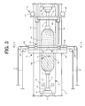
- the tension adjustment structure 24 is arranged in pairs on both front and back sides of the fixed frame 20 in correspondence to left and right guide rings 27, 28, to be hereinafter described (see Fig. 3 ).
- the helical winding head 21 is configured by two adjacently arranged guide rings 27, 28, a group of guide tubes 31 arranged at equal interval along the circumferential direction of each guide ring 27, 28, a phase switching structure 32 rotatably operating the guide ring 28 on a movable side, and the like.
- the number of guide tubes 31 attached to each guide ring 27, 28 is limited to twelve to simplify the drawing, but actually, a several dozens to a hundred and several tens of the group of guide tubes 31 are attached to the guide rings 27, 28.
- the appropriate number of fiber bundles R in carrying out helical winding can be calculated with the diameter dimension of the mandrel M, as well as, the winding width and the winding angle (angle denoted with reference symbol ⁇ in Fig. 3 ) of the fiber bundle R as variables.
- One guide ring 27 of the guide rings 27, 28 is fixed at a circumferential edge wall of the opening 20a formed in the fixed frame 20, and the other guide ring 28 is coupled in a freely rotating manner with respect to the fixed guide ring 27.
- An auxiliary frame 30 is fixed at the side end of the guide ring 28 on the movable side.
- a circular opening 30a allowing the reciprocating movement of the mandrel M is formed at a middle of the plate surface of the auxiliary frame 30, and the guide roller 22 is arranged on a plate surface at the periphery of the opening 30a (see Fig. 5 ).
- the guide tube 31 includes a linear round tube, and is screwed and fixed to each guide ring 27, 28 while being entirely tilted. Specifically, in the guide ring 27 on a fixed side, the guide tube 31 is tilted to a state a tube exit 31a is directed towards an inner side of an inner surface of the guide ring 28 on the movable side. In the guide ring 28 on the movable side, the guide tube 31 is tilted to a state where the tube exit 31a is directed towards an inner side of an inner surface of the guide ring 27 on the fixed side.
- the tube exits 31a of each guide tube 31 can be arranged as close as possible by having the tilt angle of the guide tube 31 in each guide ring 27, 28 the same, and having the respective tilting direction to opposite directions.
- the tube exits 31a, 31a are thus adjacent at a middle portion in an adjacent direction of each guide ring 27, 28 in a first state to be hereinafter described. This means the following.
- the guide rings 27, 28 adjacently arranged along an axis center of the mandrel M are coupled as shown in Fig. 6 .
- a coupling shaft 34 having smaller diameter than the ring circumferential surface is formed at a joining part of the guide ring 27 on the fixed side, and a coupling hole 35 externally fitted to the coupling shaft 34 is formed on an inner surface of a joining part of the guide ring 28 on the movable side.
- a positioning groove 36 opened at the coupling hole 35 is formed at four locations at the periphery of the joining portion of the guide ring 28 on the movable side (see Fig. 7 ).
- the rings 27, 28 are coupled in a relatively rotatable manner by joining the rings 27, 28, fitting the coupling hole 35 and the coupling shaft 34, and then screwing a hexagon socket head bolt 37 inserted to the positioning groove 36 to the coupling shaft 34.
- the guide ring 28 on the movable side is thereby coupled so as to be inseparable with respect to the guide ring 27 on the fixed side, and to be reciprocating rotation displaceable within a range defined by the positioning groove 36 and the hexagonal socket head bolt 37.
- the phase switching structure 32 is configured by an air cylinder (operator) 40 switching the guide ring 28 on the movable side, and a positioning structure arranged between the adjacent guide rings 27, 28.
- an end of a piston rod of the air cylinder 40 is coupled to a bracket 42 arranged at a lower part of the auxiliary frame 30 with a pin 43, and an end on the cylinder side of the air cylinder 40 is coupled to a bracket 44 with a pin 45.
- the latter bracket 44 is fixed to the fixed frame 20 or the mount 1.
- the auxiliary frame 30 and the guide ring 28 on the movable side can be rotatably operated in a counterclockwise rotating direction.
- the auxiliary frame 30 and the guide ring 28 on the movable side can be rotatably operated in a clockwise rotating direction.
- the positioning groove 36 and the hexagonal socket head bolt 37 described above serve as the positioning structure.
- the phase of the guide tube 31 arranged in the guide rings 27, 28 can be switched between two states by coupling the guide rings 27, 28 in a relatively rotatable manner, and rotatably operating the guide ring 28 on the movable side with the phase switching structure 32.
- One of the state is a first state in which the phase position of the guide tube 31 in each guide ring 27, 28 is matched, as shown in Fig. 4 .
- Another is a second state in which the phase position of the guide tube 31 in each guide ring 27, 28 is evenly shifted in the circumferential direction (state shown with solid line and imaginary line in Fig. 8 ).
- the amount of shift of the guide tube 31 when switched from the first state to the second state is half of the adjacent pitch in the circumferential direction of the guide tube 31 in each guide ring 27, 28.
- the number of guide tubes 31 visually recognized when facing the fixed frame 20 is twenty-four.
- the supplying number of fiber bundles R is twelve in a pseudo manner since the fiber bundle R is supplied from the guide tube 31 at the same phase position.
- the helical winding is carried out with the supplying number twice the number of fiber bundles R in the first state since the phase of the guide tube 31 in each guide ring 27, 28 is shifted.
- Numerous fiber bundles can be simultaneously wound without overlapping each other if the winding angle of the fiber bundle R is small.
- the number of fiber bundles that can be simultaneously wound without the adjacent fiber bundles R overlapping each other decreases as the winding angle becomes larger. Therefore, when changing the winding angle of the fiber bundle R with respect to the mandrel M, the number of fiber bundles R to be supplied to the mandrel M can be changed by operating the guide ring 28 on the movable side with the phase switching structure 32, and switching the supply state of the fiber bundle R between the first state and the second state.
- the winding angle of the fiber bundle R is changed by selecting the drive rotation number of the mandrel M and the feeding speed of the supporting board 2, and is determined by the shape of the mandrel M, and the size and the supplying number of the fiber bundle R.
- the phase position of the guide tube 31 in each guide ring 27, 28 in the first state is matched.
- the position in the axis center direction of the guide tube 31 in each guide ring 27, 28 tends to shift as each guide ring 27, 28 is adjacently arranged along the axis center of the mandrel M.
- the position of the tube center axis of each guide tube 31 may shift greatly in the axis center direction of the mandrel M if the guide tube 31 is radially attached along the diameter line of each guide ring 27, 28.
- the positional shift influences the winding angle of the fiber bundle R fed from each guide tube 31. Specifically, the winding angle of the fiber bundle R fed and guided by the guide tube 31 of the guide ring 27 on the fixed side becomes larger than the winding angle of the fiber bundle R fed and guided by the guide tube 31 of the guide ring 28 on the movable side.
- the distance between the position at where the fiber bundle R externally contacts the mandrel M and the tube exits 31a of each guide tube 31 differ by such shift dimension.
- the tube exits 31a, 31a of each guide tube 31 arranged in each guide ring 27, 28 are arranged close at the middle portion in the adjacent direction of the rings 27, 28, as described above. It is preferable that the adjacent interval of the tube exits 31a is as small as possible, but needs to have a margin gap so that the turning displacement of the guide ring 28 on the movable side can be smoothly performed.
- the wrapping table 16 When carrying out hoop winding, the wrapping table 16 is positioned at one side end of the cylindrical part of the mandrel M, and the fiber bundle R fed from each bobbin 17 is fixed to the surface of the mandrel M with an adhesive tape.
- a plurality of fiber bundles R is arranged in parallel without a gap along the circumferential surface of the mandrel M.
- the frame 15 is moved towards the other side end of the cylindrical part of the mandrel M while rotatably driving the wrapping table 16 in this state to form a first hoop wound layer H1.
- the frame 15 is reversed and moved to the one side end (winding start end side) of the cylindrical part of the mandrel M to form a second hoop wound layer H1.
- the winding process is performed similar to the above for the necessary number of times when further forming the hoop wound layer H1.
- the hoop winding device 3 When forming a helical wound layer H2 on the outer surface of the hoop wound layer H1, the hoop winding device 3 is retreated to one side end of the mount 1, as shown in Fig. 2 .
- the helical winding device 4 rotatably operates the guide ring 28 on the movable side with the air cylinder 40 to hold the same in the first state, and matches the phase position of the guide tube 31 in each guide ring 27, 28.
- the supporting board 2 is moved in parallel so that a basal end of the mouth part of the mandrel M faces the inner surface of the guide ring 27, 28 of the helical winding device 4, and the fiber bundle R pulled out from each guide tube 31 is fixed to the circumferential surface of the mouth part with an adhesive tape.
- the fiber bundle R pulled out from the guide tube 31, which phase is matched in each guide ring 27, 28, is fixed to the circumferential surface of the mouth part while overlapping on the inside and the outside.
- the supporting board 2 is moved at a constant speed while rotatably driving the chuck 10 and the mandrel M to form the helical wound layer H2 on the outer surface of the hoop wound layer H1.
- the supply state of the fiber bundle R in this case is the first state, and thus the helical winding is carried out in a state where the winding angle of the fiber bundle R is large.
- the tube exits 31a of the guide tubes 31, which phases are matched, are brought as close as possible.
- Fig. 3 shows a state in which the hoop wound layer H1 is formed on the surface of the mandrel M on the right side of the helical winding device 4, and the helical wound layer H2 is formed on the outer surface of the hoop wound layer H1 on the left side of the helical winding device 4.
- the helical wound layer H2 of two layers are formed on the inside and the outside when the entire mandrel M is passed through the helical winding head 21 in one direction. Similarly, the helical wound layer H2 of two layers are formed on the outer surface of the helical wound layer H2 by carrying out the helical winding while moving the supporting board 2 in the direction opposite to the direction until now. The winding process is performed similar to the above for the necessary number of times when further forming the helical wound layer H2.
- the helical winding process of small winding angle can be continuously carried out in continuation to the helical winding process of large winding angle.
- the guide ring 28 on the movable side is displaced in the clockwise rotating direction by the air cylinder 40 and held in the second state, and the phase position of the guide tube 31 in each guide ring 27, 28 is differed.
- All fiber bundles R are arranged in parallel without a gap along the circumferential surface of the helical wound layer H2 by evenly shifting the phase position of each guide tube 31 in the circumferential direction.
- the helical wound layer H2 of small winding angle can be formed by moving the supporting board 2 at a constant speed in one direction while rotatably driving the chuck 10 and the mandrel M in the above state.
- the helical wound layer H2 of small winding angle can be similarly formed by performing the helical winding while moving the supporting board 2 in the direction opposite to the direction until now. After the helical winding process is terminated, the fiber bundle R is cut, and the cut end is fixed to the mouth part with an adhesive tape.
- a pressure container including the reinforcement layer and the mandrel M is thereby obtained by alternately performing the hoop winding and the helical winding in the above manner, and then detaching the mandrel M from the supporting board 2 and applying a heating process to the detached the mandrel M to cure the resin impregnated in the fiber bundle R.
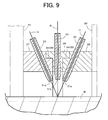
- Fig. 9 shows another example of the helical winding head 21.
- the helical winding head 21 is configured by three adjacently arranged guide rings 27, 28, 29, the group of guide tubes 31 arranged at an equal interval along the circumferential direction of each ring 27, 28, 29, the phase switching structure 32 rotatably operating the guide ring 29 at the right side end, and the like.
- the guide rings 27, 28, 29, the guide ring 27 at the left end facing Fig. 9 is fixed at the circumferential edge wall of the opening 20a formed in the fixed frame 20.
- the guide ring 28 at the middle is coupled in a freely rotating manner with respect to the fixed guide ring 27.
- the guide ring 29 at the right end facing Fig. 9 is coupled in a freely rotating manner with respect to the guide ring 28 at the middle.
- the guide ring 28 at the middle and the fixed guide ring 27, as well as the guide ring 29 at the right end and the guide ring 28 at the middle are respectively coupled in a relatively rotatable manner by the coupling structure described in Fig. 6 and Fig. 7 .
- the amount of shift of the guide tube 31 in the second state is one third of the adjacent pitch in the circumferential direction of the guide tube 31 in each guide ring 27, 28, 29, and thus the circumferential length of the positioning groove 36 is formed shorter by that much.
- the auxiliary frame 30 is fixed to the side end of the guide ring 29 at the right end, a circular opening 30a is formed at the middle of the plate surface of the auxiliary frame 30, and the guide roller 22 is arranged on the plate surface at the periphery of the opening 30a.
- the guide roller 22 guiding the fiber bundle R towards the guide ring 28 at the middle is arranged on the fixed frame 20.
- the tube exits 31a, 31a, 31a of each guide tube 31 arranged in each guide ring 27, 28, 29 are arranged close at the middle in a width direction of the inner surface of the guide ring 28 at the middle to resolve the shift of the fiber bundle R in the first state.
- the guide tube 31 is radially attached along the diameter line of the guide ring 28 in the guide ring 28 at the middle.
- the guide tube 31 is tilted in opposite directions to each other in the guide ring 27 on the fixed side and the guide ring 29 at the right end.
- the tube exits 31a, 31a, 31a of the three adjacent guide tubes 31 can be brought close to each other.
- two guide rings 28, 29 on the movable side are rotated with the phase switching structure 32 to be switched between the first state in which the phases of each guide tube 31 are matched and the second state in which the phases of each guide tube 31 are evenly shifted.
- the air cylinder 40 rotatably operates the guide ring 29 at the right end through the auxiliary frame 30, where the guide ring 28 at the middle is rotatably operated after the guide ring 29 is rotatably displaced to a limiting position.
- each guide ring 27, 28, 29 is switched to the first state, the phases of each guide tube 31 are matched, and the three tube exits 31a, 31a, 31a are brought close along the axis center direction of the mandrel M.
- the winding angle of the fiber bundle R fed from each guide tube 31 with respect to the mandrel M is substantially matched, so that the three fiber bundles R can be wound while being overlapped on the inside and the outside. Therefore, the wound layer can be appropriately formed even if the helical winding is performed in a state of large winding angle.
- the winding process can be more efficiently carried out since the helical winding is performed while simultaneously supplying the three fiber bundles R.
- each guide ring 27, 28, 29 is switched to the second state, the phases of the three tube exits 31a, 31a, 31a are evenly shifted, and the helical winding is performed with a small winding angle.
- the winding process can be efficiently performed especially when the diameter dimension of the mandrel M is large.
- each guide tube 31 attached to the guide rings 27, 28 on the fixed side and the movable side is tilted in opposite directions to each other, but is not necessary.
- the guide tube 31 attached to the guide ring 27 on the fixed side is radially attached along the diameter line of the guide ring 27, similar to the guide tube 31 positioned at the middle in Fig. 9 .
- only the guide tube 31 attached to the guide ring 28 on the movable side is greatly tilted towards the former guide tube 31, so that the tube exits 31a, 31a of the respective guide tubes 31 are brought close.
- the tube exits 31a, 31a are arranged close at the inner side of the inner surface of the guide ring 27 on the fixed side.
- Only the guide tube 31 attached to the guide ring 27 on the fixed side may be greatly tilted, so that the tube exits 31a, 31a are arranged close at the inner side of the inner surface of the guide ring 28 on the movable side.
- the guide tube 31 does not need to be formed to a linear tubular form, and the side of the tube exit 31a may be bent towards the side of the adjacent guide tube 31.
- the phase switching structure 32 can be arranged between adjacent guide rings 27, 28.
- a solenoid, an electric cylinder, and the like may be applied to the operator 40 rotatably operating the guide ring 28 on the movable side other than the air cylinder.
- the positioning structure may be formed as a dedicated structure separate from the coupling structure of each guide ring.
Landscapes
- Engineering & Computer Science (AREA)
- Mechanical Engineering (AREA)
- Moulding By Coating Moulds (AREA)
- Winding Filamentary Materials (AREA)
Applications Claiming Priority (1)
| Application Number | Priority Date | Filing Date | Title |
|---|---|---|---|
| JP2007298704A JP4403522B2 (ja) | 2007-11-16 | 2007-11-16 | フィラメントワインディング装置 |
Publications (3)
| Publication Number | Publication Date |
|---|---|
| EP2060385A2 true EP2060385A2 (de) | 2009-05-20 |
| EP2060385A3 EP2060385A3 (de) | 2010-03-24 |
| EP2060385B1 EP2060385B1 (de) | 2012-06-06 |
Family
ID=40342395
Family Applications (1)
| Application Number | Title | Priority Date | Filing Date |
|---|---|---|---|
| EP08018513A Active EP2060385B1 (de) | 2007-11-16 | 2008-10-22 | Faserwicklungsvorrichtung |
Country Status (3)
| Country | Link |
|---|---|
| US (1) | US7934530B2 (de) |
| EP (1) | EP2060385B1 (de) |
| JP (1) | JP4403522B2 (de) |
Cited By (6)
| Publication number | Priority date | Publication date | Assignee | Title |
|---|---|---|---|---|
| EP2151311A1 (de) * | 2008-08-05 | 2010-02-10 | Murata Machinery Ltd. | Faserwicklungsvorrichtung |
| EP2591907A1 (de) * | 2011-09-16 | 2013-05-15 | Murata Machinery, Ltd. | Faserwicklungsverfahren und Faserwicklungsvorrichtung |
| EP2623298A4 (de) * | 2010-09-27 | 2015-04-29 | Murata Machinery Ltd | Filamentwickelvorrichtung |
| EP2623299A4 (de) * | 2010-09-28 | 2015-05-06 | Murata Machinery Ltd | Filamentwickelvorrichtung |
| US20150329315A1 (en) * | 2014-05-14 | 2015-11-19 | Murata Machinery, Ltd. | Tank manufacturing method, helical winding device, and filament winding apparatus |
| JP2016097561A (ja) * | 2014-11-20 | 2016-05-30 | Jxエネルギー株式会社 | 複合容器の製造方法、及び複合容器 |
Families Citing this family (18)
| Publication number | Priority date | Publication date | Assignee | Title |
|---|---|---|---|---|
| JP5029134B2 (ja) * | 2007-05-15 | 2012-09-19 | 株式会社豊田自動織機 | 繊維束配列装置 |
| JP5278662B2 (ja) * | 2008-06-25 | 2013-09-04 | 村田機械株式会社 | フィラメントワインディング装置 |
| JP5443116B2 (ja) * | 2009-10-13 | 2014-03-19 | トヨタ自動車株式会社 | 繊維強化プラスチック容器の製造方法及び製造装置 |
| JP5643325B2 (ja) * | 2010-09-27 | 2014-12-17 | 村田機械株式会社 | フィラメントワインディング装置 |
| JP5687983B2 (ja) * | 2011-09-16 | 2015-03-25 | 村田機械株式会社 | フィラメントワインディング装置 |
| JP5698722B2 (ja) | 2012-10-16 | 2015-04-08 | 村田機械株式会社 | フィラメントワインディング装置 |
| FR3008469B1 (fr) * | 2013-07-11 | 2015-08-14 | Technip France | Roue de guidage pour les ensembles de pose de couches de fils d'armure |
| US10121797B2 (en) | 2016-02-22 | 2018-11-06 | Toshiba Memory Corporation | Semiconductor memory device |
| EP3241670B1 (de) * | 2016-04-01 | 2022-09-14 | Firestone Industrial Products Company, LLC | Systeme und verfahren zur herstellung flexibler federelemente für gasfederanordnungen |
| JP6881138B2 (ja) | 2017-08-07 | 2021-06-02 | 村田機械株式会社 | フィラメントワインディング装置 |
| CN110171125B (zh) * | 2019-06-18 | 2024-05-17 | 江苏贝尔机械股份有限公司 | 玻纤带自动引带装置 |
| CN113334747A (zh) * | 2021-06-07 | 2021-09-03 | 太原理工大学 | 一种高质高效纤维缠绕方法 |
| CN113386327B (zh) | 2021-06-07 | 2022-04-22 | 太原理工大学 | 一种高效率纤维螺旋缠绕装置 |
| CN113386329B (zh) * | 2021-07-01 | 2023-07-28 | 西安英利科电气科技有限公司 | 一种纤维缠绕机及缠绕方法 |
| EP4700168A1 (de) * | 2021-09-14 | 2026-02-25 | NIKE Innovate C.V. | Manipulierter vliesstoff und verfahren zur herstellung |
| CN114770922B (zh) * | 2022-05-19 | 2024-07-16 | 安徽绿动能源有限公司 | 全自动换位式多纤维缠绕一体机 |
| CN116476283A (zh) * | 2023-04-27 | 2023-07-25 | 合肥工业大学 | 一种适用于筒形件的缠绕成型模具及方法 |
| USD1107080S1 (en) * | 2023-12-08 | 2025-12-23 | Zekai Li | Bracelet making machine |
Citations (2)
| Publication number | Priority date | Publication date | Assignee | Title |
|---|---|---|---|---|
| JPH10119138A (ja) | 1996-10-21 | 1998-05-12 | Mitsubishi Heavy Ind Ltd | フィラメントワインディング製圧力容器の製造方法 |
| JP2004314550A (ja) | 2003-04-18 | 2004-11-11 | Toyota Industries Corp | Frp製パイプ及びフィラメントワインディング装置 |
Family Cites Families (5)
| Publication number | Priority date | Publication date | Assignee | Title |
|---|---|---|---|---|
| NL7610811A (nl) * | 1976-09-29 | 1978-03-31 | Lundbergs Fab Ab N | Inrichting voor de vervaardiging van gewapende buizen. |
| DE3010018A1 (de) * | 1980-03-15 | 1981-09-24 | Messerschmitt-Bölkow-Blohm GmbH, 8000 München | Verfahren und vorrichtung zum maschinellen herstellen von rohrfoermigen wickelkoerpern |
| JP4106473B2 (ja) * | 2000-12-13 | 2008-06-25 | 村田機械株式会社 | ブレイダによるエンベロープの製造方法 |
| EP1574320B1 (de) * | 2004-03-12 | 2008-10-15 | EHA Spezialmaschinenbau GmbH | Vorrichtung und Verfahren zum Aufwickeln von Fäden auf einen Formträger |
| JP5067533B2 (ja) | 2007-02-15 | 2012-11-07 | 村田機械株式会社 | フィラメントワインディング装置 |
-
2007
- 2007-11-16 JP JP2007298704A patent/JP4403522B2/ja active Active
-
2008
- 2008-10-22 EP EP08018513A patent/EP2060385B1/de active Active
- 2008-11-10 US US12/268,234 patent/US7934530B2/en active Active
Patent Citations (2)
| Publication number | Priority date | Publication date | Assignee | Title |
|---|---|---|---|---|
| JPH10119138A (ja) | 1996-10-21 | 1998-05-12 | Mitsubishi Heavy Ind Ltd | フィラメントワインディング製圧力容器の製造方法 |
| JP2004314550A (ja) | 2003-04-18 | 2004-11-11 | Toyota Industries Corp | Frp製パイプ及びフィラメントワインディング装置 |
Cited By (10)
| Publication number | Priority date | Publication date | Assignee | Title |
|---|---|---|---|---|
| EP2151311A1 (de) * | 2008-08-05 | 2010-02-10 | Murata Machinery Ltd. | Faserwicklungsvorrichtung |
| US8113457B2 (en) | 2008-08-05 | 2012-02-14 | Murata Machinery, Ltd. | Filament winding apparatus |
| EP2623298A4 (de) * | 2010-09-27 | 2015-04-29 | Murata Machinery Ltd | Filamentwickelvorrichtung |
| EP2623299A4 (de) * | 2010-09-28 | 2015-05-06 | Murata Machinery Ltd | Filamentwickelvorrichtung |
| US9067756B2 (en) | 2010-09-28 | 2015-06-30 | Murata Machinery, Ltd. | Filament winding apparatus |
| EP2591907A1 (de) * | 2011-09-16 | 2013-05-15 | Murata Machinery, Ltd. | Faserwicklungsverfahren und Faserwicklungsvorrichtung |
| US8980033B2 (en) | 2011-09-16 | 2015-03-17 | Murata Machinery, Ltd. | Filament winding method and filament winding apparatus |
| US20150329315A1 (en) * | 2014-05-14 | 2015-11-19 | Murata Machinery, Ltd. | Tank manufacturing method, helical winding device, and filament winding apparatus |
| US10087042B2 (en) * | 2014-05-14 | 2018-10-02 | Toyota Jidosha Kabushiki Kaisha | Tank manufacturing method, helical winding device, and filament winding apparatus |
| JP2016097561A (ja) * | 2014-11-20 | 2016-05-30 | Jxエネルギー株式会社 | 複合容器の製造方法、及び複合容器 |
Also Published As
| Publication number | Publication date |
|---|---|
| JP2009119803A (ja) | 2009-06-04 |
| JP4403522B2 (ja) | 2010-01-27 |
| EP2060385A3 (de) | 2010-03-24 |
| EP2060385B1 (de) | 2012-06-06 |
| US7934530B2 (en) | 2011-05-03 |
| US20090126875A1 (en) | 2009-05-21 |
Similar Documents
| Publication | Publication Date | Title |
|---|---|---|
| EP2060385B1 (de) | Faserwicklungsvorrichtung | |
| US7815141B2 (en) | Filament winding apparatus | |
| JP5278662B2 (ja) | フィラメントワインディング装置 | |
| EP2033767A2 (de) | Faserwicklungsvorrichtung | |
| JP5206949B2 (ja) | フィラメントワインディング装置及び方法 | |
| US7810754B2 (en) | Filament winding automated system | |
| US8113457B2 (en) | Filament winding apparatus | |
| EP1110895B1 (de) | Verfahren und Vorrichtung zum Wickeln von Spulen | |
| KR101485443B1 (ko) | 필라멘트 와인딩 장치 | |
| US7780110B2 (en) | Filament winding apparatus | |
| US20080197229A1 (en) | Filament winding method and apparatus | |
| US11383425B2 (en) | Filament winding device | |
| WO2018135155A1 (ja) | フィラメントワインディング法及びそれを用いるためのフィラメントワインディング装置 | |
| JP2013078959A (ja) | フィラメントワインディング装置 | |
| CN101918297A (zh) | 用于卷绕长丝的装置 | |
| JP3994853B2 (ja) | フィラメントワインディング装置 | |
| JP2010234529A (ja) | フィラメントワインディング装置 | |
| US20240051243A1 (en) | Controlled bobbin holder for a thread winding unit | |
| CN1827874A (zh) | 采样整经机、采样整经方法和旋转粗纱架 | |
| CN1654294A (zh) | 用来卷绕多股丝束的装置 | |
| JP2000108212A (ja) | 繊維供給ヘッド及び繊維供給ヘッドユニット | |
| KR20220166908A (ko) | 스프링 노트의 금속 스프링 성형기 | |
| KR101875108B1 (ko) | 연사기에서 제조된 원사의 와인딩장치 | |
| US20240399680A1 (en) | Liner replacing device | |
| WO2020119906A1 (en) | Warping and rope manufacturing machine for a rope and corresponding use |
Legal Events
| Date | Code | Title | Description |
|---|---|---|---|
| PUAI | Public reference made under article 153(3) epc to a published international application that has entered the european phase |
Free format text: ORIGINAL CODE: 0009012 |
|
| AK | Designated contracting states |
Kind code of ref document: A2 Designated state(s): AT BE BG CH CY CZ DE DK EE ES FI FR GB GR HR HU IE IS IT LI LT LU LV MC MT NL NO PL PT RO SE SI SK TR |
|
| AX | Request for extension of the european patent |
Extension state: AL BA MK RS |
|
| PUAL | Search report despatched |
Free format text: ORIGINAL CODE: 0009013 |
|
| AK | Designated contracting states |
Kind code of ref document: A3 Designated state(s): AT BE BG CH CY CZ DE DK EE ES FI FR GB GR HR HU IE IS IT LI LT LU LV MC MT NL NO PL PT RO SE SI SK TR |
|
| AX | Request for extension of the european patent |
Extension state: AL BA MK RS |
|
| RIC1 | Information provided on ipc code assigned before grant |
Ipc: B29C 53/64 20060101ALI20100218BHEP Ipc: B29C 53/66 20060101AFI20090217BHEP |
|
| 17P | Request for examination filed |
Effective date: 20100521 |
|
| 17Q | First examination report despatched |
Effective date: 20100615 |
|
| AKX | Designation fees paid |
Designated state(s): DE |
|
| GRAP | Despatch of communication of intention to grant a patent |
Free format text: ORIGINAL CODE: EPIDOSNIGR1 |
|
| GRAS | Grant fee paid |
Free format text: ORIGINAL CODE: EPIDOSNIGR3 |
|
| GRAA | (expected) grant |
Free format text: ORIGINAL CODE: 0009210 |
|
| AK | Designated contracting states |
Kind code of ref document: B1 Designated state(s): DE |
|
| REG | Reference to a national code |
Ref country code: DE Ref legal event code: R096 Ref document number: 602008016114 Country of ref document: DE Effective date: 20120802 |
|
| PLBE | No opposition filed within time limit |
Free format text: ORIGINAL CODE: 0009261 |
|
| STAA | Information on the status of an ep patent application or granted ep patent |
Free format text: STATUS: NO OPPOSITION FILED WITHIN TIME LIMIT |
|
| 26N | No opposition filed |
Effective date: 20130307 |
|
| REG | Reference to a national code |
Ref country code: DE Ref legal event code: R097 Ref document number: 602008016114 Country of ref document: DE Effective date: 20130307 |
|
| PGFP | Annual fee paid to national office [announced via postgrant information from national office to epo] |
Ref country code: DE Payment date: 20250923 Year of fee payment: 18 |