EP2060399A2 - Kopfmechanismus eines Wärmedruckers - Google Patents
Kopfmechanismus eines Wärmedruckers Download PDFInfo
- Publication number
- EP2060399A2 EP2060399A2 EP08017835A EP08017835A EP2060399A2 EP 2060399 A2 EP2060399 A2 EP 2060399A2 EP 08017835 A EP08017835 A EP 08017835A EP 08017835 A EP08017835 A EP 08017835A EP 2060399 A2 EP2060399 A2 EP 2060399A2
- Authority
- EP
- European Patent Office
- Prior art keywords
- platen roller
- head
- recording
- thermal head
- thermal
- Prior art date
- Legal status (The legal status is an assumption and is not a legal conclusion. Google has not performed a legal analysis and makes no representation as to the accuracy of the status listed.)
- Withdrawn
Links
Images

Classifications
-
- B—PERFORMING OPERATIONS; TRANSPORTING
- B41—PRINTING; LINING MACHINES; TYPEWRITERS; STAMPS
- B41J—TYPEWRITERS; SELECTIVE PRINTING MECHANISMS, i.e. MECHANISMS PRINTING OTHERWISE THAN FROM A FORME; CORRECTION OF TYPOGRAPHICAL ERRORS
- B41J2/00—Typewriters or selective printing mechanisms characterised by the printing or marking process for which they are designed
- B41J2/315—Typewriters or selective printing mechanisms characterised by the printing or marking process for which they are designed characterised by selective application of heat to a heat sensitive printing or impression-transfer material
- B41J2/32—Typewriters or selective printing mechanisms characterised by the printing or marking process for which they are designed characterised by selective application of heat to a heat sensitive printing or impression-transfer material using thermal heads
-
- B—PERFORMING OPERATIONS; TRANSPORTING
- B41—PRINTING; LINING MACHINES; TYPEWRITERS; STAMPS
- B41J—TYPEWRITERS; SELECTIVE PRINTING MECHANISMS, i.e. MECHANISMS PRINTING OTHERWISE THAN FROM A FORME; CORRECTION OF TYPOGRAPHICAL ERRORS
- B41J2202/00—Embodiments of or processes related to ink-jet or thermal heads
- B41J2202/30—Embodiments of or processes related to thermal heads
- B41J2202/31—Thermal printer with head or platen movable
Definitions
- the present invention relates to a head mechanism of a thermal printer, and particularly, to a head mechanism for obtaining good recording in a thermal printer suitable for the recording that a margin is not formed at a front end in the conveying direction of a sheet.
- a platen roller in a head mechanism of a thermal printer as a related-art example is formed from a cylindrical roller portion made of rubber, and a rotary shaft which projects from both longitudinal end surfaces of this roller portion.
- This rotary shaft is rotatably supported by a pair of side plates constituting a frame of the thermal printer, and is constructed so as to be rotationally driven under the transmission of the driving force of a driving motor.
- a thermal head which is at a front end of a head bearing member and is always brought into pressure contact with the platen roller by the biasing force of a biasing member is arranged above the platen roller.
- a line-type thermal printer in which a plurality of heat-generating elements are aligned and arranged on a metallic substrate in a direction orthogonal to a conveying direction of a thermosensitive recording medium (hereinafter simply referred to as "sheet") as a sheet provided for recording is used as this thermal head.
- the plurality of heat-generating elements of the thermal head are made to generate heat selectively with the sheet being sandwiched with pressure contact, and the platen roller is rotated, thereby performing desired recording on the sheet (for example, refer to Japanese Unexamined Patent Application Publication Nos. 2006-142569 and 2005-280017 )
- the head mechanism of the related-art thermal printer is in a state where the thermal head and the platen roller are always brought into pressure contact with each other with predetermined pressure-contact pressure by the biasing force of the biasing member even after the end of recording. Therefore, in the platen roller where the roller portion is made of rubber is deformed, the portion which the thermal head is brought into pressure contact with is deformed, and pressure-contact traces are generated in the portion. Further, blurs, streaks, etc. are generated in recording results recorded on a sheet. As a result, there is a possibility that image quality may deteriorate.
- a thermal head is brought into pressure contact with a platen roller and brought into a head-down state during recording, and the thermal head is separated from the platen roller and brought into a head-up state when recording is not performed.
- the printer which performs the up/down of the thermal head is constructed such that the thermal head is brought into a head-down state, and then recording is started. Therefore, there is a problem that a complicated mechanism is required in order to obtain desired recording, without providing a margin at the tip of a sheet, and consequently, the cost of parts increases.
- the thermal printer which is constructed such that the thermal head is always brought into pressure contact with the platen roller irrespective of whether or not recording is performed as mentioned above, are often utilized for recording of recording materials which do not require high printing quality, such as receipts, bar codes, and character documents.
- utilization of thermal printers which are constructed such that the thermal head is always brought into pressure contact with the platen roller also becomes wide. As a result, the printing quality of this thermal printer has been required.
- a head mechanism of a thermal printer including a platen roller rotatably supported by a housing, and a thermal head arranged at a front end of a head bearing member the front end of which is adapted to be rotatable about a rear end supported by the housing, and arranged to face the platen roller, and constructed such that, during recording, a sheet provided for recording is sandwiched between the platen roller and the thermal head, and an electric current is selectively applied to heat-generating elements arranged in the thermal head, thereby obtaining desired recording.
- the thermal head and the platen roller are arranged to form a gap with a dimension smaller than the thickness of the sheet provided for recording during non-recording.
- a gap is formed between the thermal head and the platen roller during non-recording.
- the trouble that pressure-contact traces of the thermal head are formed on the platen roller can be prevented.
- the gap is set to a dimension smaller than the thickness of a sheet provided for recording, a sheet to be conveyed to the gap can be sandwiched during recording. Further, by selectively applying an electric current to the heat-generating elements of the thermal head, and rotating the platen roller, a good recording result can be obtained.
- the head mechanism of a thermal printer may further include a gap adjusting means adjusting the dimension of the gap. Since such a gap adjusting means adjusting the dimension of the gap is provided, it is possible to perform recording on sheets with various width dimensions
- the gap adjusting means may be adapted such that the thermal head is able to be brought close to or separated from the arrangement position of the platen roller.
- the gap adjusting means may be a frame locking member adapted to be capable of adjusting the projection amount to the arrangement side of the platen roller, and adapted to be capable of abutting on the frame at its tip.
- the thermal head arranged above the platen roller in terms of the mounting structure of the head mechanism, adjustment operation becomes simple. Moreover, since the gap adjusting means in the invention adjusts the projection amount to the arrangement side of the platen roller, the thermal head can be brought close to or separated from the platen roller, and the dimension of the gap can be adjusted simply.
- the frame locking member may be a screw member screwed into a screw hole formed in the head bearing member and adapted to be capable of adjusting the projection amount in a state where the thermal head is arranged to face the platen roller.
- the projection amount to the arrangement side of the platen roller from the head bearing member can be simply adjusted by turning the screw member in forward or reverse directions.
- the screw member is adapted to be capable of adjusting the projection amount in a state where the thermal head is arranged to face the platen roller, the fine adjustment of the gap dimension can be performed while the gap dimension is confirmed.
- the head mechanism of the thermal printer of the aspect of the invention it is possible to solve the problem of pressure-contact traces of the platen roller while guaranteeing miniaturization of an apparatus, and obtain good recording results in a thermal printer suitable for the recording that a margin is not formed at a front end in the conveying direction of a sheet.
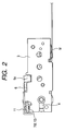
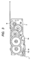
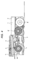
- a head mechanism of a thermal printer of this embodiment has a housing 1 made of a metal plate, and the housing 1 is formed substantially in a U-shape by a bottom plate 2 and frames 3 and 3 which face each other. Also, a platen roller 4 which is rotationally driven under the transmission of a driving force of a driving motor M is suspended between the frames 3 and 3.
- a line-type thermal head 5 in which a plurality of heat-generating elements are aligned and arranged on a metallic substrate in a direction orthogonal to a conveying direction of sheets provided for recording are arranged above the platen roller 4.
- the line type thermal head 5 is supported by a head mount (not shown), and is attached to a front end of a substantially rectangular head bearing member 6 via the head mount.
- the arrangement position of the thermal head 5 is brought close to or separated from the arrangement position of the platen roller 4 to form a gap between the platen roller 4 and the thermal head 5, and a gap adjusting means 7 for adjusting the dimension of the gap is arranged at the front end of the head bearing member 6.
- the gap adjusting means 7 in this embodiment is a frame locking member 8 which is adapted to be capable of adjusting the amount of projection to the arrangement side of the platen roller 4 in a state where the thermal head 5 is arranged to face the platen roller 4 and which is arranged so that its tip is able to abut on the frames 3 and 3, and specifically, is two screw members 10 whose tips are respectively screwed into two screw holes 9 and 9 bored in the vicinity of both longitudinal ends of the thermal head 5 in the head bearing member 6, toward the platen side, and whose screw heads are made visible recognized on the upper surface of the head bearing member 6 in plan view.
- a so-called "potato screw” is adopted.
- the projection amount of the screw member 10 to the arrangement side of the platen roller 4 becomes a gap dimension between the platen roller 4 and the thermal head 5. Therefore, when the projection amount of the screw member 10 to the arrangement side of the platen roller 4 is set to 0 mm, the thermal head 5 abuts on the peripheral surface of the platen roller 4.
- the head bearing member 6 is arranged such that a supporting shaft 6a formed at both rear ends is supported by the frame 3, and the front end where the thermal head 5 is arranged is supported rotatably with an abutting portion between the supporting shaft 6a and the frame 3 as a fulcrum.
- a top plate 11 which covers an upper surface of the front end of the head bearing member 6 where the thermal head 5 is arranged and is L-shaped in section in the sheet conveying direction is fixed to the frame 3.
- Two coil springs (not shown) are arranged at a distance from each other in the longitudinal direction of the thermal head 5 between the top plate 11 and the upper surface of the front end of the head bearing member 6, and are constructed such that the thermal head 5 may be pressed toward the platen roller 4 with a proper thrust by the biasing force of each coil spring.
- the head bearing member 6 is constructed such that the thermal head 5 is arranged to face the platen roller 4 with a desired gap therefrom by a frame locking member 8 whose tip is made to abut on the frame 3, during non-recording, and is constructed so as to rotate with the abutting portion between the supporting shaft 6a and the frame 3 as a fulcrum while resisting the biasing force of the coil spring, according to the thickness of a sheet conveyed between the thermal head 5 and the platen and to make the thermal head 5 press the sheet with a proper pressure-contact pressure, during recording.
- the screw member 10 serving as frame locking member 8 is adjusted, and during non-recording, assembling adjustment is performed such that the dimension of the gap between the thermal head 5 and the platen roller 4 is smaller than the thickness of a sheet provided for recording.
- the position where the platen roller 4 and the thermal head 5 are arranged to face each other is a recording position PP in the thermal printer.
- a sheet feed roller 12 which is rotationally driven under the transmission of the driving force of the driving motor M is arranged on the downstream side in the conveying direction of a sheet in the recording position PP.
- a sheet pressure-contact member (not shown) which is adapted to able to press a sheet along with the sheet feed roller 12 is arranged above the sheet feed roller 12.
- a gap is formed between the thermal head 5 and the platen roller 4 during non-recording like the head mechanism of the printer of this embodiment, pressure-contact traces of the thermal head 5 will not be formed on the platen roller 4. Further, by setting the gap to a dimension smaller than the thickness of a sheet provided for recording, during recording, a sheet to be conveyed to the gap is sandwiched. Further, by selectively applying an electric current to the heat-generating elements of the thermal head 5 and rotating the platen roller 4, a good recording result can be obtained.
- a concrete method of the assembling adjustment i.e. , the formation of a gap between the platen roller 4 and the thermal head 5, and a method of the dimensional adjustment are as follows.
- the gap is adjusted so as to be 0.2 mm smaller than the width dimension of the sheet.
- the tip of a driver is fitted into a bit groove formed in the screw head of the screw member 10 which is the gap adjusting means 7, the frame locking member 8, and the driver is turned such that the projection amount of the screw member 10 to the arrangement side of the platen roller 4 is set to 0 mm, and the screw member 10 is rotated such that a formed portion of the screw hole 9 in the head bearing member 6 directly abuts on the frame 3.
- the thermal head 5 is brought into a state of abutting on the peripheral surface of the platen roller 4 arranged so as to be suspended between the frames 3.
- the driver is turned in the opposite direction to reversely rotate the screw member 10, and the tip of the screw member 10 is made to project by 0.2 mm from the head bearing member 6 to the arrangement side of the platen roller 4 such that a 0.2-mm gap is formed between the platen roller 4 and the thermal head 5.
- the tip of the screw member 10 which has projected by 0.2 mm from the head bearing member 6 to the arrangement side of the platen roller 4 acts as the frame locking member 8, and abuts on the upper surface of the frame 3.
- the dimension of the gap between the platen roller 4 and the thermal head 5 can be easily adjusted by turning the screw member 10 in forward and reverse directions.
- the screw member 10 is adapted to be capable of adjusting the projection amount in a state where the thermal head 5 is arranged to face the platen roller 4.
- the screw member 10 can be rotated while the gap dimension is confirmed, and the fine adjustment of the projection amount becomes simple.
- the frame locking member 8 is the screw member 10 which is screwed into the screw hole 9 formed in the head bearing member 6, and is adapted to be capable of adjusting the projection amount in a state where the thermal head 5 is arranged to face the platen roller 4 has been described in this embodiment.
- the frame locking member a pin-like member which is fitted into a fitting hole formed in the head bearing member 6.
- the gap adjusting means 7 has been described by means of the case where the arrangement position of the thermal head 5 is brought close to or separated from the arrangement position of the platen roller 4.
- a construction in which the position where the platen roller 4 is suspended is changed with respect to the position of the thermal head 4, and is brought into close to or separated from the position of the thermal head 5 may be adopted.
- the gap adjusting means 7 is described by means of the case where the rotating head bearing member 6 is caught from below, the gap adjusting means 7 may be arranged on the side of the frame 3 of the housing, and the projection amount of the head bearing member 6 may be adjusted to perform the dimension of the gap between the platen roller 4 and the thermal head 5.
- the platen roller 4 is constructed so as to be rotationally driven under the transmission of the driving force of the driving motor M to covey sheets.
- other sheet conveying means is provided in a printer, and the platen roller 4 rotates to follow the conveyance of a sheet.
Landscapes
- Electronic Switches (AREA)
- Common Mechanisms (AREA)
- Handling Of Sheets (AREA)
Applications Claiming Priority (1)
| Application Number | Priority Date | Filing Date | Title |
|---|---|---|---|
| JP2007296700A JP2009119733A (ja) | 2007-11-15 | 2007-11-15 | サーマルプリンタのヘッド機構 |
Publications (2)
| Publication Number | Publication Date |
|---|---|
| EP2060399A2 true EP2060399A2 (de) | 2009-05-20 |
| EP2060399A3 EP2060399A3 (de) | 2009-12-30 |
Family
ID=40279024
Family Applications (1)
| Application Number | Title | Priority Date | Filing Date |
|---|---|---|---|
| EP08017835A Withdrawn EP2060399A3 (de) | 2007-11-15 | 2008-10-10 | Kopfmechanismus eines Wärmedruckers |
Country Status (4)
| Country | Link |
|---|---|
| US (1) | US7889218B2 (de) |
| EP (1) | EP2060399A3 (de) |
| JP (1) | JP2009119733A (de) |
| CN (1) | CN101434152B (de) |
Families Citing this family (6)
| Publication number | Priority date | Publication date | Assignee | Title |
|---|---|---|---|---|
| WO2019064910A1 (ja) | 2017-09-28 | 2019-04-04 | アルプスアルパイン株式会社 | サーマルプリンタ |
| WO2019103375A1 (ko) * | 2017-11-27 | 2019-05-31 | 디에스글로벌 (주) | 포토 프린터 |
| JP7018763B2 (ja) * | 2017-12-26 | 2022-02-14 | アルプスアルパイン株式会社 | 画像形成装置 |
| KR102047523B1 (ko) * | 2019-04-30 | 2019-12-02 | 디에스글로벌(주) | 포토 프린터 및 그 제조방법 |
| CN110802951B (zh) * | 2019-09-30 | 2025-06-10 | 厦门汉印股份有限公司 | 一种热敏打印机 |
| JP2025141443A (ja) | 2024-03-15 | 2025-09-29 | セイコーインスツル株式会社 | サーマルプリンタ |
Citations (3)
| Publication number | Priority date | Publication date | Assignee | Title |
|---|---|---|---|---|
| JP2005280017A (ja) | 2004-03-29 | 2005-10-13 | Alps Electric Co Ltd | サーマルプリンタのヘッド圧接機構 |
| JP2006142569A (ja) | 2004-11-17 | 2006-06-08 | Alps Electric Co Ltd | サーマルプリンタ |
| JP2007296700A (ja) | 2006-04-28 | 2007-11-15 | Aisin Seiki Co Ltd | 中空体成形装置 |
Family Cites Families (6)
| Publication number | Priority date | Publication date | Assignee | Title |
|---|---|---|---|---|
| JPS61199963A (ja) * | 1985-03-02 | 1986-09-04 | Alps Electric Co Ltd | サ−マルプリンタ− |
| JPH02155780A (ja) * | 1988-12-09 | 1990-06-14 | Tokyo Electric Co Ltd | プリンタ |
| JPH02239961A (ja) * | 1989-03-14 | 1990-09-21 | Hitachi Ltd | 熱転写記録装置 |
| JP3154622B2 (ja) * | 1994-09-09 | 2001-04-09 | 東北リコー株式会社 | サーマルプリンタ |
| JP3173335B2 (ja) * | 1995-07-28 | 2001-06-04 | 松下電器産業株式会社 | 印字装置 |
| JPH09180014A (ja) * | 1995-12-27 | 1997-07-11 | Toshiba Corp | 自動改札装置 |
-
2007
- 2007-11-15 JP JP2007296700A patent/JP2009119733A/ja not_active Withdrawn
-
2008
- 2008-10-10 EP EP08017835A patent/EP2060399A3/de not_active Withdrawn
- 2008-10-15 CN CN2008101700250A patent/CN101434152B/zh active Active
- 2008-11-13 US US12/270,326 patent/US7889218B2/en active Active
Patent Citations (3)
| Publication number | Priority date | Publication date | Assignee | Title |
|---|---|---|---|---|
| JP2005280017A (ja) | 2004-03-29 | 2005-10-13 | Alps Electric Co Ltd | サーマルプリンタのヘッド圧接機構 |
| JP2006142569A (ja) | 2004-11-17 | 2006-06-08 | Alps Electric Co Ltd | サーマルプリンタ |
| JP2007296700A (ja) | 2006-04-28 | 2007-11-15 | Aisin Seiki Co Ltd | 中空体成形装置 |
Also Published As
| Publication number | Publication date |
|---|---|
| JP2009119733A (ja) | 2009-06-04 |
| EP2060399A3 (de) | 2009-12-30 |
| US7889218B2 (en) | 2011-02-15 |
| CN101434152B (zh) | 2011-01-19 |
| US20090128614A1 (en) | 2009-05-21 |
| CN101434152A (zh) | 2009-05-20 |
Similar Documents
| Publication | Publication Date | Title |
|---|---|---|
| EP2060399A2 (de) | Kopfmechanismus eines Wärmedruckers | |
| EP2535198B1 (de) | Plattenspalt-Einstellmechanismus und Drucker | |
| EP2305478A1 (de) | Thermodrucker | |
| EP2327557A1 (de) | Wärmedrucker | |
| US9180694B2 (en) | Recording apparatus | |
| JP2004255730A (ja) | サーマルプリンタ | |
| US6262754B1 (en) | Dual type thermal printer | |
| JP4252782B2 (ja) | サーマルプリンタ | |
| JP4480076B2 (ja) | カッティングヘッド付きインクジェットプリンタ | |
| JP4595089B2 (ja) | 印画位置決め機構及びプリンタ | |
| JP4006700B2 (ja) | 熱転写プリンタ | |
| CN115923348A (zh) | 印刷装置及印刷方法 | |
| JP2001063106A (ja) | プリンタ | |
| US6031599A (en) | Photo printer with an adjustable thermal print head | |
| JP4628859B2 (ja) | サーマルヘッド位置決め機構及びサーマルプリンタ | |
| EP1867490A1 (de) | Drucktiegel und Drucker | |
| JP2908579B2 (ja) | 情報処理装置 | |
| JPH09277647A (ja) | サーマルプリンタ | |
| JP2010131818A (ja) | キャリッジ、該キャリッジを備えた液体噴射装置 | |
| JP4019297B2 (ja) | サーマルプリンタ | |
| JP3882829B2 (ja) | 熱転写プリンタおよび紙送り装置 | |
| JPH0647966A (ja) | 記録装置 | |
| JP3856321B2 (ja) | 昇華型プリンタ | |
| JPH0481519B2 (de) | ||
| JP2644637B2 (ja) | プリンター装置 |
Legal Events
| Date | Code | Title | Description |
|---|---|---|---|
| PUAI | Public reference made under article 153(3) epc to a published international application that has entered the european phase |
Free format text: ORIGINAL CODE: 0009012 |
|
| AK | Designated contracting states |
Kind code of ref document: A2 Designated state(s): AT BE BG CH CY CZ DE DK EE ES FI FR GB GR HR HU IE IS IT LI LT LU LV MC MT NL NO PL PT RO SE SI SK TR |
|
| AX | Request for extension of the european patent |
Extension state: AL BA MK RS |
|
| PUAL | Search report despatched |
Free format text: ORIGINAL CODE: 0009013 |
|
| AK | Designated contracting states |
Kind code of ref document: A3 Designated state(s): AT BE BG CH CY CZ DE DK EE ES FI FR GB GR HR HU IE IS IT LI LT LU LV MC MT NL NO PL PT RO SE SI SK TR |
|
| AX | Request for extension of the european patent |
Extension state: AL BA MK RS |
|
| 17P | Request for examination filed |
Effective date: 20100629 |
|
| AKX | Designation fees paid |
Designated state(s): DE FR GB |
|
| STAA | Information on the status of an ep patent application or granted ep patent |
Free format text: STATUS: THE APPLICATION HAS BEEN WITHDRAWN |
|
| 18W | Application withdrawn |
Effective date: 20130619 |