EP2061140A2 - Synchrone Hybridelektromaschine - Google Patents
Synchrone Hybridelektromaschine Download PDFInfo
- Publication number
- EP2061140A2 EP2061140A2 EP09001533A EP09001533A EP2061140A2 EP 2061140 A2 EP2061140 A2 EP 2061140A2 EP 09001533 A EP09001533 A EP 09001533A EP 09001533 A EP09001533 A EP 09001533A EP 2061140 A2 EP2061140 A2 EP 2061140A2
- Authority
- EP
- European Patent Office
- Prior art keywords
- stator
- rotor
- motor
- electric machine
- ring
- Prior art date
- Legal status (The legal status is an assumption and is not a legal conclusion. Google has not performed a legal analysis and makes no representation as to the accuracy of the status listed.)
- Withdrawn
Links
Images


Classifications
-
- H—ELECTRICITY
- H02—GENERATION; CONVERSION OR DISTRIBUTION OF ELECTRIC POWER
- H02K—DYNAMO-ELECTRIC MACHINES
- H02K21/00—Synchronous motors having permanent magnets; Synchronous generators having permanent magnets
- H02K21/12—Synchronous motors having permanent magnets; Synchronous generators having permanent magnets with stationary armatures and rotating magnets
- H02K21/125—Synchronous motors having permanent magnets; Synchronous generators having permanent magnets with stationary armatures and rotating magnets having an annular armature coil
-
- H—ELECTRICITY
- H02—GENERATION; CONVERSION OR DISTRIBUTION OF ELECTRIC POWER
- H02K—DYNAMO-ELECTRIC MACHINES
- H02K11/00—Structural association of dynamo-electric machines with electric components or with devices for shielding, monitoring or protection
- H02K11/01—Structural association of dynamo-electric machines with electric components or with devices for shielding, monitoring or protection for shielding from electromagnetic fields, i.e. structural association with shields
- H02K11/014—Shields associated with stationary parts, e.g. stator cores
- H02K11/0141—Shields associated with casings, enclosures or brackets
-
- H—ELECTRICITY
- H02—GENERATION; CONVERSION OR DISTRIBUTION OF ELECTRIC POWER
- H02K—DYNAMO-ELECTRIC MACHINES
- H02K5/00—Casings; Enclosures; Supports
- H02K5/04—Casings or enclosures characterised by the shape, form or construction thereof
- H02K5/16—Means for supporting bearings, e.g. insulating supports or means for fitting bearings in the bearing-shields
- H02K5/173—Means for supporting bearings, e.g. insulating supports or means for fitting bearings in the bearing-shields using bearings with rolling contact, e.g. ball bearings
- H02K5/1732—Means for supporting bearings, e.g. insulating supports or means for fitting bearings in the bearing-shields using bearings with rolling contact, e.g. ball bearings radially supporting the rotary shaft at both ends of the rotor
-
- H—ELECTRICITY
- H02—GENERATION; CONVERSION OR DISTRIBUTION OF ELECTRIC POWER
- H02K—DYNAMO-ELECTRIC MACHINES
- H02K1/00—Details of the magnetic circuit
- H02K1/06—Details of the magnetic circuit characterised by the shape, form or construction
- H02K1/12—Stationary parts of the magnetic circuit
- H02K1/14—Stator cores with salient poles
- H02K1/141—Stator cores with salient poles consisting of C-shaped cores
-
- H—ELECTRICITY
- H02—GENERATION; CONVERSION OR DISTRIBUTION OF ELECTRIC POWER
- H02K—DYNAMO-ELECTRIC MACHINES
- H02K1/00—Details of the magnetic circuit
- H02K1/06—Details of the magnetic circuit characterised by the shape, form or construction
- H02K1/12—Stationary parts of the magnetic circuit
- H02K1/14—Stator cores with salient poles
- H02K1/145—Stator cores with salient poles having an annular coil, e.g. of the claw-pole type
-
- H—ELECTRICITY
- H02—GENERATION; CONVERSION OR DISTRIBUTION OF ELECTRIC POWER
- H02K—DYNAMO-ELECTRIC MACHINES
- H02K2201/00—Specific aspects not provided for in the other groups of this subclass relating to the magnetic circuits
- H02K2201/12—Transversal flux machines
Definitions
- the present invention also pertains to a synchronous hybrid electric machine.
- the present relates to a synchronous hybrid electric machine with transverse magnetic flux whose structure is such that it minimizes eddy current losses in the motor and thus, it provides improved energy efficiency as compared to conventional motors with similar construction.
- Hybrid electric machines are a subclass of synchronous electric machines. In construction they are similar to stepper motors with in-built permanent magnets that increase magnetic filed density in the air gap, but unlikely the stepper motors, the hybrid electric machines are usually fed by sinusoidal electric currents.
- a motor of this construction is described in the European patent 0544200 , wherein it has in each phase of the stator only one coil which is coaxial with the motor axis and magnetises simultaneously a circular array of stator yokes which encircle the stator coil. Similarly, in each phase of the rotor this motor also has only one permanent magnet, which is also coaxial with the motor axis and is placed between two iron rings with salient poles on inner and outer circumference. The number of salient poles on each circumference equals the number of stator yokes.
- the machine according to the above-described constructional solution has high torque per weight and good energy efficiency. This is advantageous especially at low motor speed when efficiency of other electric motors is usually low.
- One partial solution could be replacement of metal as the building material in passive parts (especially in rotor and stator armature) with electrically insulating materials (like ceramics or plastic materials), but usually such solutions are either too expensive (for ceramics) or mechanically inadequate (for plastics).
- An object of the present invention is therefore to find such a constructional solution of stator armature, rotor armature, and iron rings of the rotor, that induction of undesirable eddy currents within these parts is strongly damped or impeded.
- the above object has been successfully achieved by a hybrid synchronous machine with transverse magnetic flux comprising a rotor and a stator, the rotor armature comprising a rotor assembly having cogged iron rings, and the rotor assembly having cross-cut insulating gaps.
- the hybrid synchronous machine also has at least one massive copper ring in close vicinity of the active motor parts.
- a hybrid synchronous electric machine with transverse magnetic flux of the present invention is characterized in that it comprises: a rotor and a stator; the rotor comprises at least one rotor assembly (13) of cogged iron rings (14, 15); and each assembly has at least one cross-cut insulating gap (22).
- the hybrid synchronous electric machine with transverse magnetic flux of the present invention is characterized in that it comprises: a rotor, a stator, and a massive conducting ring (12); and the conducting ring (12) is coaxial with the motor axis (5) and in close vicinity of the active area of the motor.
- the conducting ring (12) may be made of copper.
- the conducting ring (12) may be part of the rotor armature (11).
- cogged iron rings (14, 15) of the assembly (13) are electrically insulated from the supporting conducting ring (12).
- the stator may be assembled by at least one circular array (2) constituted by U-shaped stator yokes (3b or 3c) spaced closely together, each yoke (3b or 3c) asymmetrically consisting of two identical, but mutually overturned iron parts (23b, 24b or 23c, 24c).
- the hybrid synchronous motor according the present invention has low eddy current losses because eddy currents in cogged iron rings are impeded by cross-cut insulating gaps in these same iron rings, while eddy currents in all passive parts of the motor (like rotor armature, stator armature, and ball bearings) are negligible since the current induced in the copper ring neutralizes all the dissipated magnetic flux outside the active area of the motor. Further, this motor is very compact, strong and mechanically stable, despite low eddy current losses.
- the subject-matter of the invention also comprises a synchronous hybrid electric machine as set out in the following numbered paragraphs:
- a first embodiment (example A) of a two-phase synchronous hybrid electric machine with transverse magnetic flux according to the invention is shown.
- a circular array (2) of U-shaped stator yokes (3) which encircle the stator winding (4) of the corresponding phase.
- the windings (4) are coaxial with the motor axis (5).
- Stator yokes (3) with salient poles (6, 7) are more precisely shown in Fig. 3 .
- the yokes may be of bulk iron but it is better that the yokes (3) are lamination packages, as it is shown in Figs. 1 and 3 .
- the ferromagnetic cogged rings (14, 15) can be lamination packages, just like the stator yokes (3). (For the sake of clarity, these lamellae are not shown in Fig. 2 ).
- the magnetized disk (20) is magnetized in the axial direction so as to produce a magnetic flux that can be directed either from the cogged ring (14) to the cogged ring (15) or in the opposite direction.
- the cogged rings (14, 15) and the magnetized disk (20) can be held together by means of screws (21), as shown more precisely in Fig. 2 (A) .
- the same screws (21) can be used to fasten the rotor assembly (13) to the copper ring (12).
- the cogged rings (14, 15) are electrically insulated from the supporting copper ring (12), this can be achieved for instance by applying a thin ceramic layer onto the stems of the screws (21) and onto the surface of the copper ring (12).
- the cogged rings (14, 15) have in at least one place a narrow insulating gap (22) to prevent free circulation of circular eddy currents, as is shown in Fig. 2(A) .
- the cogged rotor rings (14, 15) and the stator yokes (3) are in the magnetic juncture; in each phase the number of stator yokes (3) is equal to the number of rotor poles (16, 17, 18, 19).
- the cogged rings (14, 15) in the assembly (13) of variant A are placed such that their outer poles (18, 19) are mutually shifted for one half of pole division, as shown in Fig. 2(A) (example A). The same holds for the inner poles (16, 17).
- stator poles attract the rotor poles towards a position which is shifted by 1/2 of the pole's division with regard to the position at the chosen moment, so that in the end position of observation the stator pole (6) coincides with the rotor pole (16) of the cogged ring (14), and the stator pole (7) coincides with the rotor pole (19) of the cogged ring (15).
- the direction of current in the winding (4) inverts. This causes the rotor to move forwards, so that it reassumes the initially observed position of mutual covering of the rotor and stator poles.
- the rotation of rotor is enabled, while the change itself can be achieved by electronic commutation.
- the solution according to the present invention applies in most of the cases, except in such cases when the nominal motor speed is so low that we cannot get Q smaller than unity.
- the copper ring (12) is not used, and the rotor armature (11) can extend into the area near the active parts of the motor. Then it is good that the armatures (11) and (1) are then made of materials with much higher electric resistance ⁇ , since in such cases we have no other means to reduce eddy currents in the passive parts of the motor.
- the ring (12) forms an attached part of the rotor armature (11), so instead of pure copper (oxygen free & high conductivity copper) which is too soft for mechanical applications, one can make a compromise by use of copper with small addition of alloying metals. In this way one can quite easily and sufficiently increase the mechanical stiffness without excessively increasing the specific resistance ⁇ .
- the problem of eddy current losses has been successfully solved by a hybrid synchronous machine with transverse magnetic flux, the rotor armature (11) comprising of at least one massive copper ring (12) in close vicinity of the active motor parts, and the rotor rings (14, 15, 20) having at least one cross-cut insulating gap (22).
- the described solution also improves the compactness of motor. Namely, the cogged iron rings (14, 15) with cross-cut insulating gaps (22) are more flexible than rings without these gaps (22), especially in the case they are lamination packages. Hence, the rotor rings (14, 15, 20) need a firm support, which can be easily provided by the massive copper ring (12).
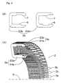
- FIG. 4 and 5 Another improvement in motor compactness, which is also a matter of the present invention, is shown in Figs. 4 and 5 . Constructions with these improvements are described as examples B and C, which introduce some modifications to the original example A shown in Fig. 3 .
- examples B and C which introduce some modifications to the original example A shown in Fig. 3 .
- the U-shaped stator yokes (3) in the circular array (2) are separated from each other.
- Some additional part e.g., made from plastic material
- this plastic part is no more necessary, since the stator yokes (3b) are not separated among themselves.
- a yoke (3b) of more complicated shape instead of one simple and symmetrical yoke (3) in variant A, in variant B we have a yoke (3b) of more complicated shape.
- this yoke (3b) is a pair of two parts (23b, 24b). These two parts (23b, 24b) are equal, but the first part (23b) is turned upside down, while the second part (24b) is turned downside up, as is seen in Fig. 4 .
- one yoke (3b) is carrying the same magnetic flux as one yoke (3) in the example A. But since there is no distance between the yokes (3b), each yoke (3b) is twice wider than the yoke (3) of variant A, and consequently the radial thickness of the yoke (3b) can be only one half of the corresponding thickness in variant A. This can be seen if we compare Figs. 3 and 4 . So also the housing of the motor can be smaller, which, together with dense packing of the stator yokes (3b), contributes to motor compactness. Another advantage is easier assembling of the motor, since in variant B there is no need to provide for separation between the stator yokes (3b).
- stator yokes (3c) are also assembled closely together into a circular array (2).
- Each yoke (3c) is in fact a pair of two parts (23c, 24c) which are again equal, with provision that the first part (23c) is turned upside down and the second part (24c) is turned downside up. Also the yokes (3c) make motor similarly compact and easy to assemble.
- the cogged rings (14c, 15c) in the assembly (13) are placed such that their outer poles (18c, 19c) are mutually shifted for one half of pole division (like in example A), and the same holds for mutual shift of the inner poles (16c, 17c). But there is no mutual shift between the poles (16c, 18c) of the first cogged ring (14c), and similarly, there is also no mutual shift between the poles (17c, 19c) of the second cogged ring (15c). Again, in Fig. 2(C) (example C) this relative poison of opposing poles on inner and outer rotor circumference is more precisely shown by the dotted line s.
- the hybrid synchronous electric machine driven by the transverse magnetic flux of the present invention is constituted to have the rotor and the stator, and the rotor armature has the cogged iron rings provided with at least one cross-cut insulating gap.
- the machine has the rotor, the stator and the conducting ring; the conducting ring is arranged coaxial with the motor axis and is in the close vicinity of the active area of the motor.
- the hybrid synchronous motor having low eddy current losses can be obtained, because eddy currents in cogged iron rings are impeded by cross-cut insulating gaps in these same iron rings.
- eddy currents in all passive parts of the motor are negligible since the current induced in the copper ring neutralizes all the dissipated magnetic flux outside the active area of the motor.
- the hybrid synchronous motor can be realized which is very compact, strong and mechanically stable, despite low eddy current losses.
Landscapes
- Engineering & Computer Science (AREA)
- Power Engineering (AREA)
- Physics & Mathematics (AREA)
- Electromagnetism (AREA)
- Iron Core Of Rotating Electric Machines (AREA)
- Permanent Magnet Type Synchronous Machine (AREA)
Applications Claiming Priority (2)
| Application Number | Priority Date | Filing Date | Title |
|---|---|---|---|
| EP01947959A EP1416619B1 (de) | 2001-07-09 | 2001-07-09 | Hybride elektrische synchronmaschine |
| PCT/JP2001/005980 WO2003007459A1 (en) | 2001-07-09 | 2001-07-09 | Hybrid synchronous electric machine |
Related Parent Applications (2)
| Application Number | Title | Priority Date | Filing Date |
|---|---|---|---|
| EP01947959A Division EP1416619B1 (de) | 2001-07-09 | 2001-07-09 | Hybride elektrische synchronmaschine |
| EP01947959.1 Division | 2001-07-09 |
Publications (2)
| Publication Number | Publication Date |
|---|---|
| EP2061140A2 true EP2061140A2 (de) | 2009-05-20 |
| EP2061140A3 EP2061140A3 (de) | 2011-08-10 |
Family
ID=11737532
Family Applications (2)
| Application Number | Title | Priority Date | Filing Date |
|---|---|---|---|
| EP09001533A Withdrawn EP2061140A3 (de) | 2001-07-09 | 2001-07-09 | Synchrone Hybridelektromaschine |
| EP01947959A Expired - Lifetime EP1416619B1 (de) | 2001-07-09 | 2001-07-09 | Hybride elektrische synchronmaschine |
Family Applications After (1)
| Application Number | Title | Priority Date | Filing Date |
|---|---|---|---|
| EP01947959A Expired - Lifetime EP1416619B1 (de) | 2001-07-09 | 2001-07-09 | Hybride elektrische synchronmaschine |
Country Status (5)
| Country | Link |
|---|---|
| US (1) | US7034425B2 (de) |
| EP (2) | EP2061140A3 (de) |
| JP (1) | JP4773053B2 (de) |
| SI (1) | SI1416619T1 (de) |
| WO (1) | WO2003007459A1 (de) |
Families Citing this family (40)
| Publication number | Priority date | Publication date | Assignee | Title |
|---|---|---|---|---|
| GB2425222B (en) * | 2005-04-12 | 2008-11-05 | Perpetuum Ltd | An electromechanical generator for converting mechanical vibrational energy into electrical energy |
| DE102005048570A1 (de) | 2005-10-10 | 2007-04-12 | Ortloff-Technologie Gmbh | Motorgetriebe mit Torquemotor und Spannungswellgetriebe |
| JP4193859B2 (ja) | 2006-04-04 | 2008-12-10 | トヨタ自動車株式会社 | モータおよびそのモータの通電制御装置 |
| DE102006050201A1 (de) * | 2006-10-25 | 2008-04-30 | Robert Bosch Gmbh | Transversalflussmaschine und Verfahren zur Herstellung einer Transversalflussmaschine |
| US20080179982A1 (en) * | 2007-01-30 | 2008-07-31 | Arvinmeritor Technology, Llc | Transverse flux, switched reluctance, traction motor with bobbin wound coil, with integral liquid cooling loop |
| US20090026869A1 (en) * | 2007-07-24 | 2009-01-29 | Christian Kaehler | Transverse flux reluctance machine and method for manufacturing same |
| GB0717746D0 (en) * | 2007-09-12 | 2007-10-24 | Univ Edinburgh | Magnetic flux conducting unit |
| US8749105B2 (en) * | 2008-05-14 | 2014-06-10 | Mitsubishi Electric Corporation | Magnetic inductor rotary machine and fluid transfer apparatus that uses the same |
| DE102009021540B4 (de) * | 2008-10-30 | 2015-09-10 | Leantec Motor Gmbh & Co. Kg | Transversalflussmotor als Außenläufermotor und Antriebsverfahren |
| EP2342803A2 (de) | 2008-11-03 | 2011-07-13 | Motor Excellence, LLC | Rotorentwürfe für ein quer- oder mischflusssystem |
| US8148841B1 (en) * | 2008-11-28 | 2012-04-03 | Scott Apthorp | Modular wind turbine system |
| WO2010089734A2 (en) * | 2009-02-05 | 2010-08-12 | Eliyahu Rozinsky | Electrical machine |
| US8035270B2 (en) * | 2009-06-30 | 2011-10-11 | American Axle & Manufacturing, Inc. | Wheel motor |
| JP5507967B2 (ja) * | 2009-11-09 | 2014-05-28 | 株式会社日立製作所 | 回転電機 |
| JP5609514B2 (ja) * | 2010-02-09 | 2014-10-22 | 富士電機株式会社 | リングコイルモータ |
| CN101771331B (zh) * | 2010-02-11 | 2012-05-30 | 哈尔滨工业大学 | 横向磁通超导同步电机 |
| WO2011115633A1 (en) | 2010-03-15 | 2011-09-22 | Motor Excellence Llc | Transverse and/or commutated flux system for electric bicycles |
| WO2011115632A1 (en) | 2010-03-15 | 2011-09-22 | Motor Excellence Llc | Transverse and/or commutated flux systems configured to provide reduced flux leakage, hysteresis loss reduction, and phase matching |
| WO2011115634A1 (en) | 2010-03-15 | 2011-09-22 | Motor Excellence Llc | Transverse and/or commutated flux systems having phase offset |
| US8854171B2 (en) | 2010-11-17 | 2014-10-07 | Electric Torque Machines Inc. | Transverse and/or commutated flux system coil concepts |
| US8952590B2 (en) | 2010-11-17 | 2015-02-10 | Electric Torque Machines Inc | Transverse and/or commutated flux systems having laminated and powdered metal portions |
| CN103477538A (zh) | 2010-11-17 | 2013-12-25 | 电动转矩机器公司 | 具有分段定子层压件的横向和/或换向磁通系统 |
| KR101259171B1 (ko) * | 2011-09-26 | 2013-04-30 | 이형진 | 고효율 전기모터, 고효율 전기 발전기 |
| JP5743988B2 (ja) * | 2012-09-18 | 2015-07-01 | 株式会社東芝 | 横方向磁束型モータ |
| WO2014107474A1 (en) | 2013-01-04 | 2014-07-10 | David Calley | Metal ribbon stator and motor comprising same |
| US9281736B2 (en) | 2013-03-23 | 2016-03-08 | The Boeing Company | Virtual ellipse motor |
| CN103178669A (zh) * | 2013-04-15 | 2013-06-26 | 王新 | 一种横向磁通相段式无刷双馈感应电机 |
| JP6634018B2 (ja) | 2013-09-18 | 2020-01-22 | イー.ヴィー.アール. モーターズ リミテッドE.V.R. Motors Ltd. | 多極電気機械 |
| US10541593B2 (en) * | 2013-11-20 | 2020-01-21 | Shanshan Dai | AC permanent-magnet switched reluctance motor |
| FR3018966A1 (fr) * | 2014-03-21 | 2015-09-25 | Mmt Sa | Machine electrique hybride |
| JP2017169343A (ja) * | 2016-03-16 | 2017-09-21 | 株式会社東芝 | 回転電機、巻上機、およびエレベータ |
| JP6649238B2 (ja) | 2016-12-13 | 2020-02-19 | 株式会社東芝 | 回転電機およびロボット装置 |
| US10608481B2 (en) * | 2016-12-15 | 2020-03-31 | General Electric Company | Core of a transverse flux machine and an associated method thereof |
| RU177973U1 (ru) * | 2017-04-21 | 2018-03-19 | федеральное государственное бюджетное образовательное учреждение высшего образования "Донской государственный технический университет" (ДГТУ) | Электрическая машина |
| WO2021212134A1 (en) * | 2020-04-14 | 2021-10-21 | Monteith Robert Lothar | Fluid turbine rotor blade |
| KR102867738B1 (ko) | 2020-09-21 | 2025-10-14 | 이브이알 모터스 엘티디. | 방사상 플럭스 전기 기계 |
| US12081073B2 (en) | 2021-10-04 | 2024-09-03 | Evr Motors Ltd | Electric machine with multi-tapered yokes |
| US12046949B1 (en) | 2023-12-28 | 2024-07-23 | Evr Motors Ltd | Electric machine with coils bridged with toothed clips |
| US12136869B1 (en) | 2023-12-28 | 2024-11-05 | Evr Motors Ltd | Heat dissipation plate for electric machine |
| US12278519B1 (en) | 2023-12-28 | 2025-04-15 | Evr Motors Ltd | Electric machine with multiple toothed spacers in coils |
Citations (1)
| Publication number | Priority date | Publication date | Assignee | Title |
|---|---|---|---|---|
| EP0544200A1 (de) | 1991-11-22 | 1993-06-02 | Andrej Detela | Hybridische Synchronmaschine mit magnetischem Transversalfluss |
Family Cites Families (25)
| Publication number | Priority date | Publication date | Assignee | Title |
|---|---|---|---|---|
| GB888462A (en) * | 1957-04-09 | 1962-01-31 | Ferranti Ltd | Improvements relating to step-by-step motors |
| US3206623A (en) * | 1962-04-20 | 1965-09-14 | Superior Electric Co | Electric synchronous inductor motor |
| DE2053262B2 (de) * | 1970-10-30 | 1972-09-21 | Robert Bosch Gmbh, 7000 Stuttgart | Wechselspannungsgenerator zur Drehzahlmessung, insbesondere für eine Blockierschutzeinrichtung einer Fahrzeugbremsanlage |
| JPS50143008A (de) | 1974-05-08 | 1975-11-18 | ||
| US4198582A (en) * | 1977-06-24 | 1980-04-15 | Exxon Research & Engineering Co. | High performance stepper motor |
| US4672247A (en) * | 1984-12-27 | 1987-06-09 | North American Philips Corporation | Synchronous or stepping motor with equal-torque stepping |
| JPH02228241A (ja) | 1989-02-28 | 1990-09-11 | Nippon Seimitsu Kogyo Kk | ステップモータ |
| SE463061B (sv) | 1989-11-20 | 1990-10-01 | Svante Gustav Adolf Von Zweygb | Permanentmagnetiserad synkronmaskin utformad enligt transversalfloedesprincipen |
| FR2664105B1 (fr) | 1990-07-02 | 1995-06-09 | Radio Energie | Moteur pas-a-pas rotatif a reluctance variable a flux transversal. |
| US5130593A (en) * | 1990-09-26 | 1992-07-14 | Connell James J | Inductor alternators |
| US5304882A (en) * | 1992-05-11 | 1994-04-19 | Electric Power Research Institute, Inc. | Variable reluctance motors with permanent magnet excitation |
| JPH06319249A (ja) * | 1993-02-19 | 1994-11-15 | Iwao Shibata | 分割型の誘導巻線を設けて誘導電動機のトルク特性を 付与したハイブリッド型パルスモータ |
| JPH06351206A (ja) * | 1993-04-14 | 1994-12-22 | Meidensha Corp | ハイブリッド励磁形永久磁石同期回転機 |
| JPH07253125A (ja) * | 1994-03-14 | 1995-10-03 | Mitsubishi Electric Corp | 磁性粒子式連結装置 |
| CA2208482C (en) * | 1994-12-21 | 2000-04-11 | Wolfgang Hill | Transverse flux machine |
| GB9516497D0 (en) | 1995-08-11 | 1995-10-11 | Rolls Royce Power Eng | Electrical machine |
| CN2264438Y (zh) * | 1996-05-06 | 1997-10-08 | 韩泰勋 | 插片式交流低速同步电动机 |
| US6043579A (en) * | 1996-07-03 | 2000-03-28 | Hill; Wolfgang | Permanently excited transverse flux machine |
| DE19800667C2 (de) * | 1998-01-10 | 2000-10-12 | Herbert Weh | Transversalflußmaschine mit massearmem passiven Rotor |
| US6091168A (en) * | 1998-12-22 | 2000-07-18 | Hamilton Sundstrand Corporation | Rotor for a dynamoelectric machine |
| JP2000197301A (ja) | 1998-12-24 | 2000-07-14 | Sony Corp | モータ |
| US6483212B1 (en) * | 1999-10-06 | 2002-11-19 | Asmo Co., Ltd. | Reluctance-type electric motor |
| SI20497B (sl) * | 2000-01-14 | 2008-08-31 | Harmonic Drive Systems | Sinhronski hibridni elektriäśni stroj s toroidnim navitjem |
| US6492758B1 (en) * | 2000-02-25 | 2002-12-10 | Fisher & Paykel Limited | Polyphase transverse flux motor |
| JP2004524800A (ja) * | 2001-05-02 | 2004-08-12 | ニューエージ インターナショナル リミテッド | トロイド状電気機械およびそれに用いる環状巻線キャリア |
-
2001
- 2001-07-09 WO PCT/JP2001/005980 patent/WO2003007459A1/ja not_active Ceased
- 2001-07-09 EP EP09001533A patent/EP2061140A3/de not_active Withdrawn
- 2001-07-09 JP JP2003513111A patent/JP4773053B2/ja not_active Expired - Lifetime
- 2001-07-09 US US10/482,308 patent/US7034425B2/en not_active Expired - Lifetime
- 2001-07-09 EP EP01947959A patent/EP1416619B1/de not_active Expired - Lifetime
- 2001-07-09 SI SI200130997T patent/SI1416619T1/sl unknown
Patent Citations (1)
| Publication number | Priority date | Publication date | Assignee | Title |
|---|---|---|---|---|
| EP0544200A1 (de) | 1991-11-22 | 1993-06-02 | Andrej Detela | Hybridische Synchronmaschine mit magnetischem Transversalfluss |
Also Published As
| Publication number | Publication date |
|---|---|
| EP1416619B1 (de) | 2011-06-08 |
| US20040207281A1 (en) | 2004-10-21 |
| SI1416619T1 (sl) | 2011-10-28 |
| EP1416619A4 (de) | 2008-02-27 |
| US7034425B2 (en) | 2006-04-25 |
| WO2003007459A1 (en) | 2003-01-23 |
| JPWO2003007459A1 (ja) | 2004-11-04 |
| EP2061140A3 (de) | 2011-08-10 |
| EP1416619A1 (de) | 2004-05-06 |
| JP4773053B2 (ja) | 2011-09-14 |
Similar Documents
| Publication | Publication Date | Title |
|---|---|---|
| US7034425B2 (en) | Hybrid synchronous electric machine | |
| US6172438B1 (en) | Two-phase permanent-magnet electric rotating machine | |
| US5977684A (en) | Rotating machine configurable as true DC generator or motor | |
| EP1734645B1 (de) | Elektromotor mit axialem Luftspalt | |
| US6700271B2 (en) | Hybrid synchronous motor equipped with toroidal winding | |
| US5521451A (en) | Low-cost stepping or synchronous motor | |
| US5089730A (en) | Low noise DC electric motor | |
| JPS63257448A (ja) | 電子的に整流されるコレクタのない直流モータ | |
| US11569717B2 (en) | Axial flux rotary electric machine | |
| WO2005034312B1 (en) | Rotary pump with electromagnetic lcr bearing | |
| US6636007B2 (en) | DC brushless vibration motor | |
| JP2002354767A (ja) | 磁気浮上電動機 | |
| US6781260B2 (en) | Permanent magnet type rotary machine | |
| EP1300931A2 (de) | Bürstenloser Gleichstrommotor | |
| JPS61180019A (ja) | 磁気軸受 | |
| US6744163B2 (en) | Vibration type brushless motor | |
| US7977827B2 (en) | Stepper motor device | |
| KR100213572B1 (ko) | 더블 스테이터 방식의 코어레스형 비엘디씨 모터 | |
| US5907205A (en) | Constant reluctance rotating magnetic field devices with laminationless stator | |
| JPH11332211A (ja) | シリンダ形リニア同期モータ | |
| JP6609138B2 (ja) | アキシャルギャップ型回転電機 | |
| JP4264021B2 (ja) | シリンダ形リニア同期モータ | |
| JP2008219993A (ja) | アキシャルギャップ型回転電機及び圧縮機 | |
| JPH0746894B2 (ja) | ブラシレスdcモ−タ | |
| JPS61203853A (ja) | 電動機 |
Legal Events
| Date | Code | Title | Description |
|---|---|---|---|
| PUAI | Public reference made under article 153(3) epc to a published international application that has entered the european phase |
Free format text: ORIGINAL CODE: 0009012 |
|
| AC | Divisional application: reference to earlier application |
Ref document number: 1416619 Country of ref document: EP Kind code of ref document: P |
|
| AK | Designated contracting states |
Kind code of ref document: A2 Designated state(s): DE GB SE |
|
| AX | Request for extension of the european patent |
Extension state: SI |
|
| PUAL | Search report despatched |
Free format text: ORIGINAL CODE: 0009013 |
|
| AK | Designated contracting states |
Kind code of ref document: A3 Designated state(s): DE GB SE |
|
| AX | Request for extension of the european patent |
Extension state: SI |
|
| RIC1 | Information provided on ipc code assigned before grant |
Ipc: H02K 21/12 20060101AFI20110705BHEP |
|
| AKY | No designation fees paid | ||
| REG | Reference to a national code |
Ref country code: DE Ref legal event code: R108 Effective date: 20120419 |
|
| STAA | Information on the status of an ep patent application or granted ep patent |
Free format text: STATUS: THE APPLICATION IS DEEMED TO BE WITHDRAWN |
|
| 18D | Application deemed to be withdrawn |
Effective date: 20120211 |