EP2061291A1 - Planche de glisse - Google Patents
Planche de glisse Download PDFInfo
- Publication number
- EP2061291A1 EP2061291A1 EP08016157A EP08016157A EP2061291A1 EP 2061291 A1 EP2061291 A1 EP 2061291A1 EP 08016157 A EP08016157 A EP 08016157A EP 08016157 A EP08016157 A EP 08016157A EP 2061291 A1 EP2061291 A1 EP 2061291A1
- Authority
- EP
- European Patent Office
- Prior art keywords
- main body
- resin
- blind bore
- binding
- fiber layer
- Prior art date
- Legal status (The legal status is an assumption and is not a legal conclusion. Google has not performed a legal analysis and makes no representation as to the accuracy of the status listed.)
- Granted
Links
- 239000002657 fibrous material Substances 0.000 claims abstract description 8
- 239000000835 fiber Substances 0.000 claims description 31
- 229920005989 resin Polymers 0.000 claims description 17
- 239000011347 resin Substances 0.000 claims description 17
- 238000004519 manufacturing process Methods 0.000 claims description 16
- 238000000034 method Methods 0.000 claims description 10
- 239000000463 material Substances 0.000 claims description 5
- 238000003825 pressing Methods 0.000 claims description 4
- 238000004026 adhesive bonding Methods 0.000 claims description 3
- 238000003780 insertion Methods 0.000 claims description 3
- 230000037431 insertion Effects 0.000 claims description 3
- 230000003313 weakening effect Effects 0.000 claims description 2
- 239000010410 layer Substances 0.000 abstract 3
- 239000002344 surface layer Substances 0.000 abstract 1
- 239000002023 wood Substances 0.000 description 13
- 239000000543 intermediate Substances 0.000 description 11
- 239000013067 intermediate product Substances 0.000 description 5
- 238000003860 storage Methods 0.000 description 5
- 239000002184 metal Substances 0.000 description 4
- 238000002360 preparation method Methods 0.000 description 4
- 230000000149 penetrating effect Effects 0.000 description 3
- XLYOFNOQVPJJNP-UHFFFAOYSA-N water Substances O XLYOFNOQVPJJNP-UHFFFAOYSA-N 0.000 description 3
- 238000005553 drilling Methods 0.000 description 2
- 210000005069 ears Anatomy 0.000 description 2
- 239000012535 impurity Substances 0.000 description 2
- 230000000712 assembly Effects 0.000 description 1
- 238000000429 assembly Methods 0.000 description 1
- 238000010276 construction Methods 0.000 description 1
- 239000000356 contaminant Substances 0.000 description 1
- 238000006073 displacement reaction Methods 0.000 description 1
- 238000001746 injection moulding Methods 0.000 description 1
- 238000009434 installation Methods 0.000 description 1
- 238000012423 maintenance Methods 0.000 description 1
- 230000013011 mating Effects 0.000 description 1
- 238000007493 shaping process Methods 0.000 description 1
- 229920003002 synthetic resin Polymers 0.000 description 1
- 239000000057 synthetic resin Substances 0.000 description 1
- 239000012780 transparent material Substances 0.000 description 1
Images
Classifications
-
- A—HUMAN NECESSITIES
- A63—SPORTS; GAMES; AMUSEMENTS
- A63C—SKATES; SKIS; ROLLER SKATES; DESIGN OR LAYOUT OF COURTS, RINKS OR THE LIKE
- A63C5/00—Skis or snowboards
- A63C5/003—Structure, covering or decoration of the upper ski surface
-
- A—HUMAN NECESSITIES
- A63—SPORTS; GAMES; AMUSEMENTS
- A63C—SKATES; SKIS; ROLLER SKATES; DESIGN OR LAYOUT OF COURTS, RINKS OR THE LIKE
- A63C5/00—Skis or snowboards
- A63C5/12—Making thereof; Selection of particular materials
- A63C5/128—A part for the binding being integrated within the board structure, e.g. plate, rail, insert
-
- F—MECHANICAL ENGINEERING; LIGHTING; HEATING; WEAPONS; BLASTING
- F16—ENGINEERING ELEMENTS AND UNITS; GENERAL MEASURES FOR PRODUCING AND MAINTAINING EFFECTIVE FUNCTIONING OF MACHINES OR INSTALLATIONS; THERMAL INSULATION IN GENERAL
- F16B—DEVICES FOR FASTENING OR SECURING CONSTRUCTIONAL ELEMENTS OR MACHINE PARTS TOGETHER, e.g. NAILS, BOLTS, CIRCLIPS, CLAMPS, CLIPS OR WEDGES; JOINTS OR JOINTING
- F16B37/00—Nuts or like thread-engaging members
- F16B37/12—Nuts or like thread-engaging members with thread-engaging surfaces formed by inserted coil-springs, discs, or the like; Independent pieces of wound wire used as nuts; Threaded inserts for holes
- F16B37/122—Threaded inserts, e.g. "rampa bolts"
Definitions
- the present invention relates to a gliding board and a gliding board intermediate comprising a plate-shaped main body and a binding mounting arrangement.
- binding mounting arrangement Under a sliding board in the context of this invention, in particular, a ski or a snowboard is to be understood, on the binding mounting arrangement a known per se bond to hold a ski or snowboard boot to be attached.
- binding mounting arrangements are usually already made during mass production of the gliding board in order to prevent later attachment of a bond to the customer, e.g. a retailer, ski rental or an end user himself.
- Common binding mounting arrangements include e.g. pre-drilled hole patterns in the main body of the gliding board so that the wearer of the ski for binding mounting no longer needs drilling tools.
- retaining rails which are already attached in the factory during the gluing of the sliding board in the main body, or various so-called inserts, which are integrated into the main body.
- inserts are e.g. enclosed between two plates of the main body and comprise of the Gleitbrettoberseite accessible threaded pieces, in which during the subsequent assembly of the bond by the customer corresponding screws can be easily screwed.
- the mentioned binding retaining rails are anchored in the production of the sliding board in the main body, so it comes due to the outwardly projecting support rails to increased storage and transport costs, since the sliding boards can not be placed flat to each other more space-saving and beyond must be ensured in that the retaining rails do not damage adjacent sliding boards.
- a gliding board comprising a plate-shaped main body, at least one binding mounting arrangement disposed in a central portion of the main body and adapted for attachment thereto, and an upper cover layer disposed above the main body externally exposed, the main body having in the central portion at least one blind bore opening towards the top of the main body, the binding mounting assembly comprising at least one threaded bushing inserted into the at least one blind bore of the main body, between the screwed socket and the Walls or / and the bottom of the blind bore a resin-carrying fiber material is arranged, and wherein the cover layer as a closed layer covers the main body and the at least one binding mounting arrangement and the upper opening of the at least one Screw bush closes.
- top refers to a normal orientation of the gliding board intermediate product in which the substantially plate-shaped gliding board intermediate is aligned parallel to a horizontal plane, the binding mounting arrangement to an upper side points and indicates a sliding surface to the lower side.
- the sliding board has at least one blind bore in the middle section of the main body into which a correspondingly dimensioned threaded bushing is inserted from above.
- a correspondingly dimensioned threaded bushing is inserted from above.
- the threaded bushing is fixedly connected to the walls and / or the bottom of the blind bore by a resin-carrying fiber material arranged therebetween. During production, the resin of the fiber material hardens and thus establishes in a simple manner a firm connection between bushing and blind bore, without the need for additional form-locking connection systems.
- the upper opening of the at least one screw bushing is covered and closed by the cover layer, so that no water or contaminants can penetrate into the threaded bushing.
- the cover layer advantageously covers not only the opening of the threaded bushing but also a large area, preferably the entire upper side of the main body and thus simultaneously serves as the upper terminating layer of the sliding board. In this way, the manufacturing costs can be further reduced and quality losses during transport / storage by penetrating water or impurities can be avoided.
- the resin-carrying fiber material may preferably be formed by a so-called prepreg layer, ie by a nonwoven mat impregnated with synthetic resin.
- the screw bushings are advantageously inexpensive available screw anchors with or without internal thread, or are designed as threaded bushes with standardized internal thread. If the threaded bushes substantially do not protrude beyond the surface of the sliding board, sliding boards according to the invention can be stacked flat on top of each other without the risk of mutual damage, so that transport and storage costs are reduced.
- the binding mounting assembly further comprises a binding plate mounted on the main body, wherein one or more resin-carrying fiber material is disposed between the main body and the binding plate, and wherein the binding plate has at least one hole through which the interior of the threaded socket is accessible.
- a binding plate according to this embodiment may be made of metal or plastic and serves to protect the main body in the area of the binding against mechanical stresses which act on the gliding board from the binding.
- a binding plate has a plurality of holes and is thus assigned to an arrangement of a plurality of threaded bushes of the binding mounting arrangement.
- a substantially planar sliding board upper side can be created which has the advantages mentioned above in view of the transport and storage costs, and on the other hand, a quick yet accurate positioning of the binding plate with respect to the threaded bushings are made possible because the upper portion of the threaded bushing snaps into place in the hole of the binding plate, thereby arresting a positioning of the binding plate.
- the binding plate is firmly connected to the at least one threaded bushing. Also in this case, positioning of the binding plate relative to the threaded socket is facilitated.
- a binding plate and at least one threaded bushing are combined to form a one-piece molded article, and e.g. manufactured in one piece as an injection molding.
- a sliding board intermediate comprising a plate-shaped main body having in a central portion at least one blind bore opening towards the top of the main body, at least one resin-impregnated fiber layer disposed on the main body and which covers at least one blind bore, at least one binding mounting assembly comprising at least one threaded bushing adapted to fit into the at least one blind bore of the main body.
- Such a gliding board intermediate can be produced inexpensively because, compared with a corresponding prior art gliding board intermediate in which no binding mounting arrangement is provided, the plate-shaped main body of the invention need only have the at least one blind bore and the resin-impregnated fiber layer.
- the resin-impregnated fiber layer can be easily applied to the top of the main body, so that it covers the at least one blind bore. With a correspondingly more generous dimensioning of the resin-impregnated fiber layer, such an arrangement can be provided quickly and cost-effectively, in particular if a fiber layer covers several blind holes.
- the sliding board intermediate according to the invention is preferably an intermediate for the preparation of the invention described above Sliding board.
- the invention further provides a simple and economical method comprising at least the following steps: producing a plate-shaped main body, forming at least one blind bore in a central portion of the main body opening towards the top of the main body, applying at least one resin impregnated fiber layer on the upper side of the main body, so that the resin impregnated fiber layer covers the at least one blind bore, impressing a screw bushing in the resin impregnated fiber layer above the blind bore, so that the screw bush penetrates into the blind bore, wherein a portion of the resin impregnated fiber layer in a region between the Screw bushing and the walls barter / and the bottom of the blind hole is pressed, and curing of the resin of the resin-impregnated fiber layer.
- the at least one threaded bushing can be firmly and firmly anchored in the main body during manufacture or mass production of the gliding board in a simple
- an upper covering layer is applied to the upper side of the main body, which covers at least the upper opening of the at least one threaded bushing and thus closes securely against the entry of water or impurities.
- the upper cover layer may preferably extend over the substantially entire surface of the main body and thus simultaneously an outer cover layer of the Form sliding boards.
- the resin-impregnated fiber layer may have an incision or a material weakening above the at least one blind bore, so that a defined displacement of the resin-impregnated fiber layer into the blind bore is facilitated by the action of the penetrating threaded bushing.
- Such an incision may be designed approximately cross-shaped, so that the resulting four ears of the fiber layer can be easily bent into the interior of the blind bore.
- the resin-impregnated fiber layer extends over at least two blind holes and over a surface area of the main body extending between the at least two blind holes, then not only the at least two blind holes can be equipped with only one applied fiber layer, but at the same time a simple and firm one Prepared for attachment of a binding plate. Namely, at the same time as the step of pushing the at least one screw bushing into the associated blind bore, namely, in the above-mentioned manufacturing method, a bonding plate may be pressed against the top of the main body so that the resin impregnated fiber layer is between the bonding plate and the main body.
- the resin of the fiber layer is then allowed to cure also in the region below the binding plate, so that the at least one threaded bushing as well as the binding plate are simultaneously firmly connected to the main body. This is then possible in particular using only a single resin-impregnated fiber layer, which at the same time supplies binding plate and screw bushing with the necessary resin.
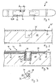
- FIG. 1 is a ski according to the embodiment of the invention generally designated 10.
- this has an elongated shape, wherein two binding mounting arrangements 12, 12 are mounted in its longitudinally central portion, in which later a binding, not shown, of the ski is to be fastened.
- Each of the binding mounting assemblies 12, 12 includes a binding plate 14 and a plurality of threaded bushes 16 disposed below the binding plate 14. The interior of the screw bushing 16 is accessible from outside through correspondingly arranged holes 18 of the binding plate 14.
- the binding plates 14, 14 have a certain number and arrangement of the holes 18, which correspond to a certain number and arrangement of screw bushings 16 and are adapted to one or more standardized types of bonds.
- the corresponding matching bond can thus be screwed by matched screws with the associated ringbuchsen 16.
- Number and arrangement of the threaded bushes 16 and, accordingly, the holes 18 of the binding plate 14 may accordingly according to the type of bond or the be selected to be used binding types.
- the two can in FIG. 1 distinguishable binding mounting arrangements from each other with respect to number and arrangement of the threaded bushes 16 and holes 18 from each other.
- FIG. 2 shows an enlarged view of a section of an intermediate product according to the invention 10 'for the preparation of in FIG. 1 Skis shown in a cross section according to line II-II of FIG. 1 , It should be noted that FIG. 2 no screw bush, binding plate or cover layer shows; Although these elements may be part of the intermediate according to the invention, they are still kept separate in the production stage corresponding to the intermediate product 10 '.
- the intermediate product 10 has a wood core 20 and a running surface 22 attached to the underside of the wood core 20.
- the wood core 20 extends over the entire length and width of the ski 10 and represents the main shaping element of the ski.
- the wood core 20 can be formed of several parts, for example several layers.
- a blind bore 22 is introduced from an upper side 24 of the wood core 20.
- the blind bore 22 extends from the top 24 of a piece far into the wood core 20 and ends there to form a bottom of the blind bore.
- a resin impregnated Nonwoven mat 26 placed so that it rests both in the vicinity of the blind bore 22 on the upper side 24 of the wood core 20, as well as over the blind bore 22 away.
- the nonwoven mat 26 is provided with a cross-shaped incision 28 (see FIG. 3 ), wherein a center 30 of the cross-shaped incision 28 approximately corresponds to the center of the bore 22 and the length d of each of the four sections of the incision 28 corresponds approximately to the radius of the blind bore 22.
- the incision 28 may be made in the manufacturing process before or after applying the nonwoven mat 26 to the wood core 20.
- screw bushings 16 are provided, which are sized so that they fit into the respective blind bore 22.
- the threaded bushings 16 may have different configurations depending on the screw means to be used.
- screw bushings 16 can be used, the interior of which gradually tapers from the open upper side towards the closed lower side, so that the interior of the screw bushing 16 corresponds in cross section accordingly FIG. 4 has a conical shape.
- Such a screw bushing 16 can be used in particular in conjunction with correspondingly tapered screws (wood screws, sheet metal screws, etc.) with coarse thread pitch.
- Such fferbuchsen 16 are known for example in the art as dowels and usually have no pronounced thread. Instead, the thread of the screw cuts into the material of the dowel (preferably plastic).
- the screw bushing may have a cylindrical shape in its interior and be provided on its inner wall with a prefabricated thread.
- the threaded bushing is then preferably made of metal and for cooperation with a suitable one set up cylindrical metal screw.
- the threaded bushing 16 through the nonwoven mat 26 into the blind bore 22 into pressed In this case, the four ears 32 of the non-woven mat 26 formed by the incision 28 fold (cf. FIGS. 3 and 4 ) in the interior of the blind bore 22 and are squeezed between the penetrating threaded sleeve 16 and the side walls or the bottom of the blind bore 22. Resin material is pressed out of the non-woven mat and distributed in the area between the screw bushing 16 and blind bore 22.
- the screw bushing 16 also has barbs 36 on its outer circumference, as in FIG FIG. 4 easy to recognize.
- the barbs 36 run as annular ribs about the outer circumference of the threaded bushing 16. The barbs dig a little way into the wall of the blind bore 22 and also provide an enlarged surface for the resin material.
- the binding plate 14 is pressed onto the nonwoven mat 26, wherein the binding plate 14 is thereby positioned so that the hole 18 is aligned with the opening of the threaded bushing 16. Due to the compressive force, the resin of the nonwoven mat 26 is distributed in the region between the binding plate 14 and the upper side 24 of the wood core 20.
- the resin of the nonwoven mat 26 is allowed to cure until a sufficiently firm connection between the screw bushing 16 and blind bore 22 or between the binding plate 14 and the wood core 20 is made.
- a cover layer 34 is applied to the upper side of the ski 10, which extends over the entire upper side of the ski 10 and also extends over both binding mounting arrangements 12, 12. In the area of each screw bushing 16, the cover layer 34 covers the opening of the screw bush 16 and thus closes it.
- the ski 10 made in this manner may then be delivered to a customer, i. a dealer, lender or the like.
- the customer can then attach a unified bond to the bond mount assembly in a simple manner and without much tooling by screwing suitable screwing means into the mating screw jacks.
- suitable screwing means into the mating screw jacks.
- the positions of the screw bushings can be easily recognized by the customer if the upper cover layer is made of transparent material.
- the upper cover layer above the screw bushes sink marks due to the underlying cavity. Such sink marks are easy to see from the outside, so that the position of the screw bushings are clearly visible even when using a non-transparent cover layer.
Landscapes
- Engineering & Computer Science (AREA)
- General Engineering & Computer Science (AREA)
- Mechanical Engineering (AREA)
- Connection Of Plates (AREA)
- Mounting Of Printed Circuit Boards And The Like (AREA)
Applications Claiming Priority (1)
| Application Number | Priority Date | Filing Date | Title |
|---|---|---|---|
| DE202007015913U DE202007015913U1 (de) | 2007-11-14 | 2007-11-14 | Gleitbrett |
Publications (2)
| Publication Number | Publication Date |
|---|---|
| EP2061291A1 true EP2061291A1 (fr) | 2009-05-20 |
| EP2061291B1 EP2061291B1 (fr) | 2012-03-28 |
Family
ID=38989984
Family Applications (1)
| Application Number | Title | Priority Date | Filing Date |
|---|---|---|---|
| EP08016157A Not-in-force EP2061291B1 (fr) | 2007-11-14 | 2008-09-12 | Planche de glisse |
Country Status (3)
| Country | Link |
|---|---|
| EP (1) | EP2061291B1 (fr) |
| AT (1) | ATE551103T1 (fr) |
| DE (1) | DE202007015913U1 (fr) |
Citations (3)
| Publication number | Priority date | Publication date | Assignee | Title |
|---|---|---|---|---|
| FR2595579A1 (fr) * | 1986-03-14 | 1987-09-18 | Salomon Sa | Ski pourvu de prepercages pour le montage des fixations |
| US5016901A (en) * | 1988-08-11 | 1991-05-21 | Tmc Corporation | Ski |
| DE19748464A1 (de) | 1997-01-04 | 1998-07-23 | Voelkl Franz Ski | Gleitbrett, insbesondere Snowboard sowie Verankerungssystem zur Befestigung einer Bindung oder dergleichen Funktionselement an einem Gleitbrett |
-
2007
- 2007-11-14 DE DE202007015913U patent/DE202007015913U1/de not_active Expired - Lifetime
-
2008
- 2008-09-12 AT AT08016157T patent/ATE551103T1/de active
- 2008-09-12 EP EP08016157A patent/EP2061291B1/fr not_active Not-in-force
Patent Citations (3)
| Publication number | Priority date | Publication date | Assignee | Title |
|---|---|---|---|---|
| FR2595579A1 (fr) * | 1986-03-14 | 1987-09-18 | Salomon Sa | Ski pourvu de prepercages pour le montage des fixations |
| US5016901A (en) * | 1988-08-11 | 1991-05-21 | Tmc Corporation | Ski |
| DE19748464A1 (de) | 1997-01-04 | 1998-07-23 | Voelkl Franz Ski | Gleitbrett, insbesondere Snowboard sowie Verankerungssystem zur Befestigung einer Bindung oder dergleichen Funktionselement an einem Gleitbrett |
Also Published As
| Publication number | Publication date |
|---|---|
| ATE551103T1 (de) | 2012-04-15 |
| EP2061291B1 (fr) | 2012-03-28 |
| DE202007015913U1 (de) | 2008-01-31 |
Similar Documents
| Publication | Publication Date | Title |
|---|---|---|
| EP3735152B1 (fr) | Ensemble d'un panneau de meuble et d'une ferrure de déplacement avec élément de montage intégré pour le panneau mobile, le corps du meuble et les meubles comprenant un tel panneau de meuble | |
| DE102004054368A1 (de) | Verkleidungspaneel | |
| EP3057774B1 (fr) | Pièce munie d'une partie fixation permettant un assemblage par vis et pièce moulée et élément de fixation | |
| EP0901447A1 (fr) | Planche de surf ou planche a voile et procede de production | |
| DE2610200A1 (de) | Beschlag zum loesbaren verbinden von bauteilen, insbesondere zum wieder loesbaren verbinden von plattenfoermigen bauteilen | |
| EP0292742A1 (fr) | Vis d'écartement | |
| EP2381815B1 (fr) | Dispositif de fixation pour le montage d'une étagère murale | |
| DE102008056435A1 (de) | Befestigungselement für ein Verlegesystem zur Erstellung eines Wand-, Boden- oder Deckenbelags, ein solches Verlegesystem sowie ein Verfahren zum Verlegen von Belagelementen | |
| DE102010051388B4 (de) | Verbindungsanordnung | |
| DE102015112563A1 (de) | Verbindungsanordnung zum Verbinden eines Pfostens an einem Rahmenprofil eines Fensters oder einer Türe aus Kunststoff | |
| DE69620234T2 (de) | Snowboard-einlegeplatte | |
| EP2061291B1 (fr) | Planche de glisse | |
| EP1611927A1 (fr) | Planche de glisse sur neige | |
| EP0852157A2 (fr) | Planche de glisse, notamment snowboard ainsi que systène d'ancrage pour l'arrimage d'une fixation ou élément fonctionnel analogue sur une planche de glisse | |
| EP2487372B1 (fr) | Agencement de fixation et son procédé de fabrication | |
| DE102020123839B4 (de) | Verbindungselement für ein Möbelstück, Stecksystem mit einem solchen Verbindungselement und ein Verfahren zur Montage eines Möbelstücks | |
| WO2018172356A1 (fr) | Boîtier électronique et procédé pour l'encapsulation de composants électroniques | |
| DE3923413A1 (de) | Kinderspielgeraet | |
| EP2155016A2 (fr) | Système de meuble et meuble | |
| DE102023114385B3 (de) | Höhenverstellbarer Möbelfuß | |
| EP1563879B1 (fr) | Planche de glisse, en particulier ski | |
| DE19748464A1 (de) | Gleitbrett, insbesondere Snowboard sowie Verankerungssystem zur Befestigung einer Bindung oder dergleichen Funktionselement an einem Gleitbrett | |
| DE102005048995B4 (de) | Bindungsbauteil | |
| DE102024119654A1 (de) | Befestigungselement für ein Bauteil, insbesondere zur Integration in ein Fahrzeug oder ein Möbelstück, Plattenelement, Bauteil, Fahrzeug sowie Verfahren zur Herstellung eines Plattenelements und eines Bauteils | |
| EP0300148A1 (fr) | Plaque de base pour fixation de ski |
Legal Events
| Date | Code | Title | Description |
|---|---|---|---|
| PUAI | Public reference made under article 153(3) epc to a published international application that has entered the european phase |
Free format text: ORIGINAL CODE: 0009012 |
|
| AK | Designated contracting states |
Kind code of ref document: A1 Designated state(s): AT BE BG CH CY CZ DE DK EE ES FI FR GB GR HR HU IE IS IT LI LT LU LV MC MT NL NO PL PT RO SE SI SK TR |
|
| AX | Request for extension of the european patent |
Extension state: AL BA MK RS |
|
| 17P | Request for examination filed |
Effective date: 20090723 |
|
| AKX | Designation fees paid |
Designated state(s): AT CH DE LI |
|
| REG | Reference to a national code |
Ref country code: DE Ref legal event code: R079 Ref document number: 502008006781 Country of ref document: DE Free format text: PREVIOUS MAIN CLASS: H05K0005000000 Ipc: A63C0005000000 |
|
| RIC1 | Information provided on ipc code assigned before grant |
Ipc: H05K 5/00 20060101ALI20110823BHEP Ipc: F16B 37/12 20060101ALI20110823BHEP Ipc: A63C 5/00 20060101AFI20110823BHEP Ipc: F16B 5/01 20060101ALI20110823BHEP |
|
| GRAP | Despatch of communication of intention to grant a patent |
Free format text: ORIGINAL CODE: EPIDOSNIGR1 |
|
| GRAS | Grant fee paid |
Free format text: ORIGINAL CODE: EPIDOSNIGR3 |
|
| GRAA | (expected) grant |
Free format text: ORIGINAL CODE: 0009210 |
|
| AK | Designated contracting states |
Kind code of ref document: B1 Designated state(s): AT CH DE LI |
|
| REG | Reference to a national code |
Ref country code: CH Ref legal event code: EP |
|
| REG | Reference to a national code |
Ref country code: AT Ref legal event code: REF Ref document number: 551103 Country of ref document: AT Kind code of ref document: T Effective date: 20120415 |
|
| REG | Reference to a national code |
Ref country code: DE Ref legal event code: R096 Ref document number: 502008006781 Country of ref document: DE Effective date: 20120524 |
|
| PLBE | No opposition filed within time limit |
Free format text: ORIGINAL CODE: 0009261 |
|
| STAA | Information on the status of an ep patent application or granted ep patent |
Free format text: STATUS: NO OPPOSITION FILED WITHIN TIME LIMIT |
|
| 26N | No opposition filed |
Effective date: 20130103 |
|
| REG | Reference to a national code |
Ref country code: DE Ref legal event code: R097 Ref document number: 502008006781 Country of ref document: DE Effective date: 20130103 |
|
| PGFP | Annual fee paid to national office [announced via postgrant information from national office to epo] |
Ref country code: CH Payment date: 20150918 Year of fee payment: 8 Ref country code: DE Payment date: 20150630 Year of fee payment: 8 |
|
| PGFP | Annual fee paid to national office [announced via postgrant information from national office to epo] |
Ref country code: AT Payment date: 20150921 Year of fee payment: 8 |
|
| REG | Reference to a national code |
Ref country code: DE Ref legal event code: R119 Ref document number: 502008006781 Country of ref document: DE |
|
| REG | Reference to a national code |
Ref country code: CH Ref legal event code: PL |
|
| REG | Reference to a national code |
Ref country code: AT Ref legal event code: MM01 Ref document number: 551103 Country of ref document: AT Kind code of ref document: T Effective date: 20160912 |
|
| PG25 | Lapsed in a contracting state [announced via postgrant information from national office to epo] |
Ref country code: DE Free format text: LAPSE BECAUSE OF NON-PAYMENT OF DUE FEES Effective date: 20170401 Ref country code: LI Free format text: LAPSE BECAUSE OF NON-PAYMENT OF DUE FEES Effective date: 20160930 Ref country code: CH Free format text: LAPSE BECAUSE OF NON-PAYMENT OF DUE FEES Effective date: 20160930 |
|
| PG25 | Lapsed in a contracting state [announced via postgrant information from national office to epo] |
Ref country code: AT Free format text: LAPSE BECAUSE OF NON-PAYMENT OF DUE FEES Effective date: 20160912 |