EP2061987B1 - Gasspeicher sowie biogasanlage mit einem gasspeicher - Google Patents
Gasspeicher sowie biogasanlage mit einem gasspeicher Download PDFInfo
- Publication number
- EP2061987B1 EP2061987B1 EP07818143A EP07818143A EP2061987B1 EP 2061987 B1 EP2061987 B1 EP 2061987B1 EP 07818143 A EP07818143 A EP 07818143A EP 07818143 A EP07818143 A EP 07818143A EP 2061987 B1 EP2061987 B1 EP 2061987B1
- Authority
- EP
- European Patent Office
- Prior art keywords
- gas reservoir
- wall
- gas
- return pulley
- stabilising element
- Prior art date
- Legal status (The legal status is an assumption and is not a legal conclusion. Google has not performed a legal analysis and makes no representation as to the accuracy of the status listed.)
- Not-in-force
Links
- 238000009434 installation Methods 0.000 title 1
- VNWKTOKETHGBQD-UHFFFAOYSA-N methane Chemical compound C VNWKTOKETHGBQD-UHFFFAOYSA-N 0.000 claims description 6
- 230000000295 complement effect Effects 0.000 claims description 2
- 239000011888 foil Substances 0.000 claims description 2
- 230000003019 stabilising effect Effects 0.000 claims 10
- 239000002759 woven fabric Substances 0.000 claims 1
- 230000000087 stabilizing effect Effects 0.000 description 32
- 238000000855 fermentation Methods 0.000 description 11
- 230000004151 fermentation Effects 0.000 description 11
- 239000000463 material Substances 0.000 description 5
- 239000012528 membrane Substances 0.000 description 5
- 210000003608 fece Anatomy 0.000 description 3
- 239000010871 livestock manure Substances 0.000 description 3
- 230000006641 stabilisation Effects 0.000 description 3
- 238000011105 stabilization Methods 0.000 description 3
- 230000001419 dependent effect Effects 0.000 description 2
- 230000033228 biological regulation Effects 0.000 description 1
- 230000003247 decreasing effect Effects 0.000 description 1
- 239000004744 fabric Substances 0.000 description 1
- 239000007788 liquid Substances 0.000 description 1
- 238000004519 manufacturing process Methods 0.000 description 1
- 230000002787 reinforcement Effects 0.000 description 1
- 230000003313 weakening effect Effects 0.000 description 1
Images



Classifications
-
- F—MECHANICAL ENGINEERING; LIGHTING; HEATING; WEAPONS; BLASTING
- F17—STORING OR DISTRIBUTING GASES OR LIQUIDS
- F17B—GAS-HOLDERS OF VARIABLE CAPACITY
- F17B1/00—Gas-holders of variable capacity
- F17B1/24—Gas-holders of variable capacity of dry type
- F17B1/26—Gas-holders of variable capacity of dry type with flexible walls, e.g. bellows
-
- C—CHEMISTRY; METALLURGY
- C12—BIOCHEMISTRY; BEER; SPIRITS; WINE; VINEGAR; MICROBIOLOGY; ENZYMOLOGY; MUTATION OR GENETIC ENGINEERING
- C12M—APPARATUS FOR ENZYMOLOGY OR MICROBIOLOGY; APPARATUS FOR CULTURING MICROORGANISMS FOR PRODUCING BIOMASS, FOR GROWING CELLS OR FOR OBTAINING FERMENTATION OR METABOLIC PRODUCTS, i.e. BIOREACTORS OR FERMENTERS
- C12M21/00—Bioreactors or fermenters specially adapted for specific uses
- C12M21/04—Bioreactors or fermenters specially adapted for specific uses for producing gas, e.g. biogas
-
- C—CHEMISTRY; METALLURGY
- C12—BIOCHEMISTRY; BEER; SPIRITS; WINE; VINEGAR; MICROBIOLOGY; ENZYMOLOGY; MUTATION OR GENETIC ENGINEERING
- C12M—APPARATUS FOR ENZYMOLOGY OR MICROBIOLOGY; APPARATUS FOR CULTURING MICROORGANISMS FOR PRODUCING BIOMASS, FOR GROWING CELLS OR FOR OBTAINING FERMENTATION OR METABOLIC PRODUCTS, i.e. BIOREACTORS OR FERMENTERS
- C12M23/00—Constructional details, e.g. recesses, hinges
- C12M23/26—Constructional details, e.g. recesses, hinges flexible
-
- C—CHEMISTRY; METALLURGY
- C12—BIOCHEMISTRY; BEER; SPIRITS; WINE; VINEGAR; MICROBIOLOGY; ENZYMOLOGY; MUTATION OR GENETIC ENGINEERING
- C12M—APPARATUS FOR ENZYMOLOGY OR MICROBIOLOGY; APPARATUS FOR CULTURING MICROORGANISMS FOR PRODUCING BIOMASS, FOR GROWING CELLS OR FOR OBTAINING FERMENTATION OR METABOLIC PRODUCTS, i.e. BIOREACTORS OR FERMENTERS
- C12M23/00—Constructional details, e.g. recesses, hinges
- C12M23/36—Means for collection or storage of gas; Gas holders
-
- Y—GENERAL TAGGING OF NEW TECHNOLOGICAL DEVELOPMENTS; GENERAL TAGGING OF CROSS-SECTIONAL TECHNOLOGIES SPANNING OVER SEVERAL SECTIONS OF THE IPC; TECHNICAL SUBJECTS COVERED BY FORMER USPC CROSS-REFERENCE ART COLLECTIONS [XRACs] AND DIGESTS
- Y02—TECHNOLOGIES OR APPLICATIONS FOR MITIGATION OR ADAPTATION AGAINST CLIMATE CHANGE
- Y02E—REDUCTION OF GREENHOUSE GAS [GHG] EMISSIONS, RELATED TO ENERGY GENERATION, TRANSMISSION OR DISTRIBUTION
- Y02E50/00—Technologies for the production of fuel of non-fossil origin
- Y02E50/30—Fuel from waste, e.g. synthetic alcohol or diesel
Definitions
- the invention relates to a gas storage according to the preamble of claim 1 and a biogas plant for the production of biogas, in particular methane, with such a gas storage.
- From the DE 202 08 171 U is a structurally simple and relatively inexpensive to use value gas container known.
- This has a cylindrical gas space, which is laterally bounded by a flexible wall, the bottom of a floor and the top of a ceiling.
- the ceiling When filling the gas space with gas, the ceiling is raised against the weight of the gas pressure and moves away from the ground increasingly.
- the gas space is thereby larger.
- the wall is associated with a plurality of expansion limiters, which are movable with the wall and affect their shape forcibly. The expansion limiters stabilize the wall of the gas storage.
- the gas container described works in principle very reliable. In the filled state of the gas container, however, it may happen due to laterally attacking winds or as a result of manual intervention that the walls of the gas container together with the expansion limiters dodge horizontally to the side and the operation is disturbed.
- Such a gas container is from the FR 680304A in that shows the features of the preamble of claim 1, already known.
- the invention has for its object to develop a gas storage of the type mentioned, which is structurally simple and reliable even in permanent operation and to provide a biogas plant with such a gas storage ready.
- the stabilizing element is designed to be flexible and, depending on the filling state of the gas space, tightened in whole or in part by tensile stress by means of a tensioning device between one or more pairs of cooperating abutments.
- the tightened part of the stabilizing element prevents lateral breaking of the wall.
- the respectively tightened part of the stabilizing element is not changed in a change in the size of the gas space in its relative position to the wall of the gas space. This ensures that the wall is not rubbed off on the stabilizing element becomes. A permanently reliable operation of the gas storage is ensured.
- the stabilizing element is preferably formed by a net, a rope, a fabric, a foil or the like. However, combinations of two or more of these embodiments of the stabilizing element are also possible.
- the clamping device acts on the stabilizing element with advantage with a tensile stress, which is aligned substantially parallel to the wall of the gas reservoir.
- the tensile stress forms a counterforce to the expansion of the wall.
- the stabilizing element is preferably applied in the vertical direction with a tensile stress.
- the tensile stress is preferably transmitted from a directly or indirectly on the stabilizing element attacking draw weight and / or at least one spring on the stabilizing element.
- the draw weight can be formed by a separate element or cost-saving from the ceiling of the gas storage.
- the operating pressure in the interior of the gas space can be increased without having to increase the tensile stress acting on the stabilizing elements.
- the tension can be increased without having to increase the operating pressure in the interior of the gas space by the train weights increased and at the same time attached to the brackets Weights of the blanket are reduced. A targeted and variable regulation of the operating pressure and the tension of the stabilizing elements is thus ensured in a simple manner.
- the ceiling can be made of a plate.
- it can also consist of a frame, for example a support ring, which is lined with a gas-tight membrane towards the gas space, this membrane being connected in a gas-tight manner to the wall.
- the wall has at least one folding aid, with the help of a uniform folding of the wall is made possible in a decreasing gas space.
- the folding aid can either be connected to the wall, for example in the form of the wall and running parallel to the ground rings. However, the folding aid can also be part of the wall in the form of material reinforcements and material weakenings at selected locations.
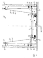
- FIGS. 1 and 2 show a gas storage 2 according to the invention with a variable-size gas space 4, the in Fig. 1 filled and in Fig. 2 is almost empty.
- the gas space 4 is bounded laterally by a flexible wall 6 with a cylindrical basic shape and on the upper side by a cover 8 connected in a gas-tight manner to the wall 6.
- On the underside, the gas space 4 is limited by a bottom 10. The filling of the gas space 4 with gas and the removal of gas via a recessed in the bottom 10 gas port 11th
- the wall 6 and the ceiling 8 are formed as movable parts, as from the comparison of FIGS. 1 and 2 is apparent.
- the extent of the wall 6 is bounded laterally by stabilizing elements 12.
- the stabilizing elements 12 are evenly distributed around the wall 6 around.
- Fig. 1 and 2 each of the left and the right side of the illustrated gas storage 2 are the same structure: Hereinafter, for the sake of simplicity, only one of the pages will be explained occasionally. However, the explanation applies equally to the other side of the gas storage 2.
- the stabilizing element 12 of each side is inherently flexible and is formed in the embodiment of a network.
- the gas storage 2 has in the in Fig. 1 and 2 illustrated embodiment on each side of the gas storage a clamping device, each with a pair of cooperating abutment 14, 16. A portion of the stabilizing element 12 is tensioned between the cooperating abutments 14, 16 by a tensile stress.
- the respective upper abutment 14 are fixedly connected to the ceiling as a movable part, whereas the lower abutment are not attached to one of the moving parts but at the bottom 18 outside the gas space 4 laterally adjacent to the wall 6.
- the lower abutment 16 are formed as deflection rollers 16.
- the tensioning device on each side urges the stabilizing element 12 with a tensile stress which is aligned substantially parallel to the wall 6 of the gas reservoir 2 in its gas-filled state.
- the wall 6 is formed by the tensioned nets 12 in the area between the abutments 14, 16 are prevented from expanding or shifting beyond the nets 12.
- the relative position of the wall 6 to the streamlined parts of the stabilizing elements 12 next to the wall 6 remains constant with a change in the size of the gas space 4.
- Wall 6 and this on an expansion outwardly limiting taut stabilizing element 12 perform during a change in size of the gas chamber 4, the same movement relative to the bottom 10 or 18.
- the tensioning device on each side has in each case a draw weight 20 which acts indirectly on the stabilizing element 12 for applying the tensile force via a tension element 22, the stabilizing element 12 being guided around the deflection roller 16.
- the draw weight 20 can also act directly on the stabilization element 12.
- the train weight can be formed by the ceiling itself, whereby the total weight and the required amount of material of the gas storage can be further reduced cost-reducing. Both aforementioned embodiments are not shown in the figures.
- the deflection rollers 16 are each associated with further deflection rollers 24 which are arranged further away from the base 18 than the respective first deflection roller 16.
- the stabilization element 12 is guided starting from its attachment to the ceiling 8 as a further abutment 14 around the respectively first deflection roller 16.
- the tension elements 22 are each connected via connecting means 26 with the stabilizing element 12 and are guided over the further deflection roller 24 up to the end-side draw weight 20, which is connected to the tension element 22.
- the ceiling 8 is pushed away on the one hand from the prevailing pressure in the gas chamber 4 operating pressure of about 50 millibar above the external pressure from the bottom 10. On the other hand, this pressure counteracts the weight of the blanket 8.
- the ceiling 8 is pulled over the stabilizing elements 12 and the tensile elements 22 acting thereon by the draw weights 20 in the direction of the bottom 10 of the gas space 4.
- the ceiling 8 operates with respect to the gas space 4 similar to a piston.
- the further deflection roller 24 is attached to a support 28 which is adjacent to the gas space 4.
- two struts 30 are arranged with end guide means 32 in the form of two rollers.
- the guide means 32 are movable along these associated and complementary to these trained guide rails 34.
- the guide rails 34 are arranged in the exemplary embodiment of the supports 28.
- two rollers are provided as a guide means 32 per strut.
- the struts 30 and the attached end-side rollers 32 are aligned with the ceiling 8 so that an unwanted inclination of the ceiling 8, for example, as a result of not uniformly running pulleys 16, 24, relative to the wall 6 is prevented.
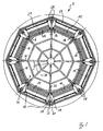
- Fig. 3 shows a further embodiment of a gas storage device 2 according to the invention in plan view.
- the gas storage 2 has eight stabilizing elements 12 and correspondingly eight first deflection rollers 16.
- the stabilizing elements 12 thus form in plan view essentially a uniform octagon. It has been found that good stabilization of the wall 6 can be achieved by this preferred embodiment. Of course, depending on the size and shape of the gas space 4, however, more or less stabilizing elements 12 may be provided.
- the deflection rollers 16 are each formed as rollers 16, around which in each case the stabilizing element 12 is guided.
- the rollers 16 each have a further deflection roller 24 is assigned, which is also formed in the embodiment as a roller 24.
- the further rollers 24 are each mounted between two supports 28.
- the gas storage 2 also has a substantially cylindrical wall 6 here.
- the gas storage 2 consists of an octagonal in plan view ceiling frame 36 and a ceiling membrane 38 which is connected to the gas-tight wall 6.
- the ceiling membrane 38 in Fig. 3 made transparent to indicate the underlying position of the wall 6 can.
- each struts 30 are mounted in extension of the ceiling frame 36, at which end the guide means 32 in the in Fig. 1 and 2 shown Sort are arranged.
- the guide means 32 are preferably formed in the form of two superimposed rollers.
- the guide means 32 are movable on guide rails 34, which are each arranged on the supports 28.
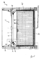
- Fig. 4 and 5 show a biogas plant 40 according to the invention with a fermentation tank 42 above which a gas storage 2 of the type described above is arranged.
- the gas storage 2 is gas-tightly connected to the fermentation tank 42 and in Fig. 4 fuller than in Fig. 5 ,
- the headspace of the fermentation tank 42 or the biogas plant 40 is formed by the gas storage 2.
- the gas space 4 of the gas storage 2 is limited downwards either from the bottom 44 or from a liquid in the fermentation tank, for example manure.
- a fermentation solution such as manure or manure, from the fermentation processes biogas, especially methane, is formed.
- the biogas is then stored in the gas storage 2 preferably under pressure.
- the supports 28 of the gas storage 2 are used simultaneously as supports of the fermentation tank 42. Between the supports 28 while a grid structure 46 is arranged, which is designed on the inside with a liquid-tight fermentation tank membrane 48.
- a grid structure 46 is arranged, which is designed on the inside with a liquid-tight fermentation tank membrane 48.
- the other abutment 16 can then be designed as deflection rollers fixed to the ceiling. As a result, it is possible to dispense with the further deflection rollers 24.
- Fig. 6 shows the magnification of the section A from Fig. 5
- the gas storage 2 has in principle the same elements, which are also in Fig. 1 and 2 are shown.
- the gas storage 2 is gas-tight connected to the fermentation tank 42.
Landscapes
- Health & Medical Sciences (AREA)
- Engineering & Computer Science (AREA)
- Life Sciences & Earth Sciences (AREA)
- Chemical & Material Sciences (AREA)
- Wood Science & Technology (AREA)
- Organic Chemistry (AREA)
- Bioinformatics & Cheminformatics (AREA)
- Zoology (AREA)
- Genetics & Genomics (AREA)
- General Engineering & Computer Science (AREA)
- Biomedical Technology (AREA)
- Biotechnology (AREA)
- Biochemistry (AREA)
- Microbiology (AREA)
- General Health & Medical Sciences (AREA)
- Sustainable Development (AREA)
- Clinical Laboratory Science (AREA)
- Molecular Biology (AREA)
- Mechanical Engineering (AREA)
- General Chemical & Material Sciences (AREA)
- Oil, Petroleum & Natural Gas (AREA)
- Filling Or Discharging Of Gas Storage Vessels (AREA)
Description
- Die Erfindung betrifft einen Gasspeicher nach dem Oberbegriff des Anspruchs 1 sowie eine Biogasanlage zur Erzeugung von Biogas, insbesondere Methan, mit einem derartigen Gasspeicher.
- Aus der
DE 202 08 171 U ist ein konstruktiv einfacher und relativ zum Gebrauchswert preisgünstiger Gasbehälter bekannt. Dieser weist einen zylindrischen Gasraum auf, der seitlich von einer flexiblen Wandung, unterseitig von einem Boden und oberseitig von einer Decke begrenzt wird. Beim Befüllen des Gasraumes mit Gas wird die Decke entgegen deren Gewichtskraft durch den Gasdruck angehoben und entfernt sich zunehmend vom Boden. Der Gasraum wird dadurch größer. Der Wandung sind mehrere Ausdehnungsbegrenzer zugeordnet, die mit der Wandung beweglich sind und deren Formgebung zwangsbeeinflussen. Die Ausdehnungsbegrenzer stabilisieren die Wandung des Gasspeichers. - Der beschriebene Gasbehälter arbeitet im Prinzip sehr zuverlässig. Im befüllten Zustand des Gasbehälters kann es jedoch infolge seitlich angreifender Winde oder infolge manuellen Eingreifens dazu kommen, daß die Wandungen des Gasbehälters zusammen mit den Ausdehnungsbegrenzern horizontal zur Seite hin ausweichen und der Betrieb dadurch gestört wird.
- Um ein derartiges Ausweichen der Wandung zur Seite zu unterbinden, ist die Anordnung eines Käfigs um den Gasbehälter herum im Stand der Technik vorgeschlagen worden. Ein derartiger Gasbehälter ist aus der
FR 680304A - Diese Konstruktion hat jedoch den Nachteil, daß die Wandung des Gasbehälters, sofern diese seitlich ausweicht und die Ausweichbewegung vom Käfig gestoppt wird, an dem Käfig entlang streifen und infolge von Reibungskräften mit der Zeit abnutzen kann.
- Der Erfindung liegt die Aufgabe zugrunde, einen Gasspeicher der eingangs genannten Art zu entwickeln, der konstruktiv einfach aufgebaut ist und auch im dauerhaften Betrieb zuverlässig arbeitet sowie eine Biogasanlage mit einem derartigen Gasspeicher bereit zu stellen.
- Die Erfindung löst diese Aufgabe durch einen Gasspeicher mit den Merkmalen des Anspruchs 1 sowie durch eine Biogasanlage mit den Merkmalen des Anspruchs 15. Vorteilhafte Ausgestaltungen ergeben sich aus den abhängigen Ansprüchen 2 bis 14 und 16.
- Das Stabilisierungselement ist flexibel ausgebildet und je nach Füllzustand des Gasraumes ganz oder teilweise mit Hilfe einer Spanneinrichtung zwischen einem oder mehreren Paaren zusammenwirkender Widerlager durch Zugspannung gestrafft. Der gestraffte Teil des Stabilisierungselements verhindert ein seitliches Ausbrechen der Wandung. Da zusätzlich lediglich eines der jeweils zusammenwirkenden Widerlager fest mit einem der beweglichen Teile verbunden ist, wird der jeweils gestraffte Teil des Stabilisierungselements auch bei einer Änderung der Größe des Gasraumes in seiner relativen Position zur Wandung des Gasraumes nicht verändert. Hierdurch wird sichergestellt, daß die Wandung nicht an dem Stabilisierungselement abgerieben wird. Ein dauerhaft zuverlässiger Betrieb des Gasspeichers ist so sichergestellt.
- Das Stabilisierungselement wird bevorzugt von einem Netz, einem Seil, einem Gewebe, einer Folie oder dergleichen gebildet. Es sind jedoch auch Kombinationen zweier oder mehrerer dieser Ausgestaltungen des Stabilisierungselementes möglich.
- Die Spanneinrichtung beaufschlagt das Stabilisierungselement mit Vorteil mit einer Zugspannung, die im wesentlichen parallel zur Wandung des Gasspeichers ausgerichtet ist. Die Zugspannung bildet dabei eine Gegenkraft zur Ausdehnung der Wandung. Im Falle einer zylindrischen Form des Gasraumes mit einer im wesentlichen vertikal ausgerichteten Wandung ist auch das Stabilisierungselement bevorzugt in vertikaler Richtung mit einer Zugspannung beaufschlagt. Die Zugspannung wird bevorzugt von einem direkt oder indirekt am Stabilisierungselement angreifenden Zuggewicht und/oder wenigstens einer Feder auf das Stabilisierungselement übertragen. Das Zuggewicht kann dabei von einem separaten Element oder aber kostensparend von der Decke des Gasspeichers gebildet werden.
- An der Decke sind mit Vorteil Halterungen zur Anbringung zusätzlicher Gewichte an oder auf der Decke vorgesehen. Hierdurch kann der Betriebsdruck im Inneren des Gasraumes erhöht werden, ohne die auf die Stabilisierungselemente einwirkende Zugspannung erhöhen zu müssen. Umgekehrt kann jedoch auch die Zugspannung erhöht werden ohne den Betriebsdruck im Inneren des Gasraumes erhöhen zu müssen, indem die Zuggewichte erhöht und gleichzeitig die an den Halterungen befestigten Gewichte der Decke reduziert werden. Eine gezielte und variable Regulierung des Betriebsdruckes und der Zugspannung der Stabilisierungselemente ist dadurch in einfacher Weise gewährleistet.
- Die Decke kann von einer Platte gebildet werden. Um Gewicht und Kosten zu sparen, kann sie jedoch auch aus einem Gestell, beispielsweise einem Tragring, bestehen, das zum Gasraum hin mit einer gasdichten Membran unterlegt ist, wobei diese Membran gasdicht mit der Wandung verbunden ist. Hierdurch ist der Transport und Aufbau des Gasspeichers deutlich vereinfacht.
- In einer bevorzugten Ausgestaltung der Erfindung weist die Wandung wenigstens eine Falthilfe auf, mit deren Hilfe eine gleichmäßige Faltung der Wandung bei einem sich verkleinernden Gasraum ermöglicht wird. Die Falthilfe kann dabei entweder mit der Wandung verbunden sein, beispielsweise in Form um die Wandung und parallel zum Boden laufender Ringe. Die Falthilfe kann jedoch auch Teil der Wandung in Form von Materialverstärkungen und Materialschwächungen an ausgewählten Stellen sein.
- Weitere Ausgestaltungen und Vorteile der Erfindung ergeben sich aus den Unteransprüchen und den nachfolgend beschriebenen Ausführungsbeispielen in den Figuren; es zeigen:
- Fig. 1
- einen erfindungsgemäßen Gasspeicher mit zwei Stabilisierungselementen in teilweise geschnittener Seitenansicht,
- Fig. 2
- den Gegenstand aus
Fig. 1 mit fast leerem Gasraum, - Fig. 3
- einen erfindungsgemäßen Gasspeicher mit acht Stabilisierungselementen in der Draufsicht,
- Fig. 4
- eine erfindungsgemäße Biogasanlage mit gefülltem Gasspeicher in teilweise geschnittener Seitenansicht,
- Fig. 5
- den Gegenstand aus
Fig. 4 mit fast leerem Gasspeicher und - Fig. 6
- eine Vergrößerung des Ausschnittes A aus
Fig. 5 . - Nachfolgend werden gleichwirkende Elemente mit einem einheitlichen Bezugszeichen versehen.
- Die
Figuren 1 und2 zeigen einen erfindungsgemäßen Gasspeicher 2 mit einem größenvariablen Gasraum 4, der inFig. 1 gefüllt und inFig. 2 fast entleert ist. Der Gasraum 4 wird seitlich durch eine flexible Wandung 6 mit einer zylindrischen Grundform und oberseitig durch eine mit der Wandung 6 gasdicht verbundene Decke 8 begrenzt. Unterseitig wird der Gasraum 4 durch einen Boden 10 begrenzt. Die Befüllung des Gasraumes 4 mit Gas und die Entnahme von Gas erfolgt über einen im Boden 10 eingelassenen Gasanschluß 11. - Die Wandung 6 und die Decke 8 sind als bewegliche Teile ausgebildet, wie aus dem Vergleich der
Figuren 1 und2 ersichtlich ist. Die Ausdehnung der Wandung 6 wird seitlich durch Stabilisierungselemente 12 begrenzt. Die Stabilisierungselemente 12 sind gleichmäßig um die Wandung 6 herum verteilt. InFig. 1 und2 sind jeweils die linke und die rechte abgebildete Seite des Gasspeichers 2 gleich aufgebaut: Nachfolgend wird der Einfachheit halber gelegentlich lediglich eine der Seiten erläutert. Die Erläuterung gilt jedoch gleichermaßen auch für die andere Seite des Gasspeichers 2. - Das Stabilisierungselement 12 jeder Seite ist in sich flexibel und wird in dem Ausführungsbeispiel von einem Netz gebildet. Der Gasspeicher 2 weist in dem in
Fig. 1 und2 dargestellten Ausführungsbeispiel auf jeder Seite des Gasspeichers eine Spanneinrichtung mit jeweils einem Paar zusammenwirkender Widerlager 14, 16 auf. Ein Teil des Stabilisierungselements 12 ist zwischen den zusammenwirkenden Widerlagern 14, 16 durch eine Zugspannung gespannt. Die jeweils oberen Widerlager 14 sind fest mit der Decke als einem beweglichen Teil verbunden, wohingegen die unteren Widerlager nicht an einem der beweglichen Teile sondern am Boden 18 außerhalb des Gasraumes 4 seitlich neben der Wandung 6 befestigt sind. Die unteren Widerlager 16 sind als Umlenkrollen 16 ausgebildet. - Die Spanneinrichtung jeder Seite beaufschlagt das Stabilisierungselement 12 mit einer Zugspannung, die im wesentlichen parallel zur Wandung 6 des Gasspeichers 2 in dessen mit Gas befülltem Zustand ausgerichtet ist. Die Wandung 6 wird durch die unter Zugspannung stehenden Netze 12 im Bereich zwischen den Widerlagern 14, 16 an einer Ausdehnung oder Verlagerung über die Netze 12 hinaus gehindert. Gleichzeitig wird durch die Anordnung sichergestellt, daß die an die Stabilisierungselemente 12 angelehnte Wandung 6 bei einer Größenänderung des Gasraumes 4 nicht an den Stabilisierungselementen 12 entlang reibt und die Wandung 6 dadurch beschädigt wird. Die relative Position der Wandung 6 zu den gestrafften Teilen der Stabilisierungselemente 12 neben der Wandung 6 bleibt bei einer Änderung der Größe des Gasraumes 4 stets gleich. Wandung 6 und das diese an einer Dehnung nach außen begrenzende gestraffte Stabilisierungselement 12 führen während einer Größenänderung des Gasraumes 4 die gleiche Bewegung relativ zum Boden 10 oder 18 aus.
- Die Spanneinrichtung jeder Seite weist jeweils ein Zuggewicht 20 auf, das zur Aufbringung der Zugkraft indirekt über ein Zugelement 22 an dem Stabilisierungselement 12 angreift, wobei das Stabilisierungselement 12 um die Umlenkrolle 16 geführt wird. Das Zuggewicht 20 kann jedoch auch direkt an dem Stabilisierungselement 12 angreifen. Auch kann das Zuggewicht von der Decke selbst gebildet werden, wodurch das Gesamtgewicht und die benötigte Materialmenge des Gasspeichers kostenreduzierend weiter gesenkt werden kann. Beide vorgenannten Ausgestaltungen sind in den Figuren jedoch nicht dargestellt.
- Den Umlenkrollen 16 sind jeweils weitere Umlenkrollen 24 zugeordnet, die weiter vom Boden 18 entfernt angeordnet sind als die jeweils erste Umlenkrolle 16. Das Stabilisierungselement 12 ist ausgehend von dessen Befestigung an der Decke 8 als weiterem Widerlager 14 um die jeweils erste Umlenkrolle 16 geführt. Die Zugelemente 22 sind jeweils über Verbindungsmittel 26 mit dem Stabilisierungselement 12 verbunden und werden über die weitere Umlenkrolle 24 bis zu dem endseitigen Zuggewicht 20 geführt, das mit dem Zugelement 22 verbunden ist.
- Im Ergebnis wird die Decke 8 einerseits von dem im Gasraum 4 herrschenden Betriebsdruck von etwa 50 Millibar über dem Außendruck vom Boden 10 weggedrückt. Diesem Druck wirkt andererseits das Eigengewicht der Decke 8 entgegen. Zudem wird die Decke 8 über die Stabilisierungselemente 12 sowie die daran angreifenden Zugelemente 22 durch die Zuggewichte 20 in Richtung Boden 10 des Gasraumes 4 gezogen. Die Decke 8 arbeitet bezüglich des Gasraumes 4 ähnlich einem Kolben.
- Die weitere Umlenkrolle 24 ist an einer Stütze 28 befestigt, die neben dem Gasraum 4 steht. An der Decke 8 sind zwei Streben 30 mit endseitigen Führungsmitteln 32 in Form von jeweils zwei Rollen angeordnet. Die Führungsmittel 32 sind entlang diesen zugeordneter und komplementär zu diesen ausgebildeter Führungsschienen 34 verfahrbar. Die Führungsschienen 34 sind im Ausführungsbeispiel an den Stützen 28 angeordnet. Hierdurch kann Material und damit Kosten eingespart werden. Im Ausführungsbeispiel sind je Strebe 30 zwei Rollen als Führungsmittel 32 vorgesehen. Die Streben 30 bzw. die daran befestigten endseitigen Rollen 32 sind dabei so zur Decke 8 ausgerichtet, daß eine ungewollte Schrägstellung der Decke 8, zum Beispiel in Folge nicht gleichmäßig laufender Umlenkrollen 16, 24, relativ zur Wandung 6 verhindert wird.
-
Fig. 3 zeigt eine weitere Ausgestaltung eines erfindungsgemäßen Gasspeichers 2 in der Draufsicht. Der Gasspeicher 2 weist acht Stabilisierungselemente 12 und entsprechend acht erste Umlenkrollen 16 auf. Die Stabilisierungselemente 12 bilden so in der Draufsicht im wesentlichen ein gleichmäßiges Achteck. Es hat sich gezeigt, daß durch diese bevorzugte Ausgestaltung eine gute Stabilisierung der Wandung 6 erzielt werden kann. Selbstverständlich können je nach Größe und Form des Gasraumes 4 jedoch auch mehr oder weniger Stabilisierungselemente 12 vorgesehen sein. - Die Umlenkrollen 16 sind dabei jeweils als Walzen 16 ausgebildet, um die jeweils das Stabilisierungselement 12 geführt wird. Den Walzen 16 ist jeweils eine weitere Umlenkrolle 24 zugeordnet, die im Ausführungsbeispiel ebenfalls als Walze 24 ausgebildet ist. Es ist jedoch auch möglich, eine der Umlenkrollen 16, 24 als Walze und die andere nicht als Walze auszubilden. Die weiteren Walzen 24 sind jeweils zwischen zwei Stützen 28 befestigt.
- Der Gasspeicher 2 weist auch hier eine im wesentlichen zylindrische Wandung 6 auf. Der Gasspeicher 2 besteht aus einem in der Draufsicht achteckigen Deckengestell 36 und einer Deckenmembran 38, die mit der Wandung 6 gasdicht verbunden ist. Zur besseren Übersicht ist die Deckenmembran 38 in
Fig. 3 durchsichtig gestaltet, um die darunterliegende Lage der Wandung 6 andeuten zu können. - An der Decke 8 sind in Verlängerung des Deckengestells 36 jeweils Streben 30 angebracht, an denen endseitig die Führungsmittel 32 in der in
Fig. 1 und2 dargestellten Art angeordnet sind. Auch hier werden die Führungsmittel 32 bevorzugt in Form von zwei übereinanderlaufenden Rollen gebildet. Die Führungsmittel 32 sind an Führungsschienen 34 verfahrbar, die jeweils an den Stützen 28 angeordnet sind. -
Fig. 4 und5 zeigen eine erfindungsgemäße Biogasanlage 40 mit einem Gärbehälter 42 oberhalb dessen ein Gasspeicher 2 der zuvor beschriebenen Art angeordnet ist. Der Gasspeicher 2 ist mit dem Gärbehälter 42 gasdicht verbunden und inFig. 4 voller als inFig. 5 . Der Kopfraum des Gärbehälters 42 bzw. der Biogasanlage 40 wird vom Gasspeicher 2 gebildet. Der Gasraum 4 des Gasspeichers 2 wird nach unten hin entweder vom Boden 44 oder aber von einer im Gärbehälter befindlichen Flüssigkeit, zum Beispiel Gülle, begrenzt. In dem Gärbehälter 42 befindet sich eine Fermentationslösung, wie z.B. Gülle oder Jauche, aus der über Fermentationsprozesse Biogas, insbesondere Methan, gebildet wird. Das Biogas wird dann im Gasspeicher 2 bevorzugt unter Druck gespeichert. - Zweckmäßigerweise werden die Stützen 28 des Gasspeichers 2 gleichzeitig als Stützen des Gärbehälters 42 verwendet. Zwischen die Stützen 28 ist dabei eine Gitterkonstruktion 46 angeordnet, die innenseitig mit einer flüssigkeitsdichten Gärbehältermembran 48 ausgelegt ist. Durch eine derartige Anordnung kann die Biogasanlage 40 mit leichten Materialien und in einfacher Weise schnell aufgebaut werden.
- Bedingt durch die gegenüber der Umgebung erhöhte Lage des Gasspeichers 2 kann die als weiteres Widerlager 14 wirkende Fixierung der Stabilisierungselemente 12 auch nicht an den beweglichen Teilen Decke 8 oder Wandung 6 erfolgen, sondern beispielsweise am Gärbehälter 42. Die weiteren Widerlager 16 können dann als Umlenkrollen ausgebildet an der Decke fixiert werden. Hierdurch kann auf die weiteren Umlenkrollen 24 verzichtet werden.
-
Fig. 6 zeigt die Vergrößerung des Ausschnitts A ausFig. 5 . Der Gasspeicher 2 weist prinzipiell die gleichen Elemente auf, die auch inFig. 1 und2 dargestellt sind. Der Gasspeicher 2 ist gasdicht mit dem Gärbehälter 42 verbunden.
Claims (14)
- Gasspeicher (2), mit einem größenvariablen Gasraum (4), der zumindest bereichsweise von einer flexiblen Wandung (6) und einer Decke (8) als beweglichen Teilen begrenzt ist, mit wenigstens einem die Ausdehnung der Wandung (6) zumindest bereichsweise begrenzenden Stabilisierungselement (12), das flexibel ist,und mit zumindest einer Spanneinrichtung mit wenigstens einem Paar zusammenwirkender Widerlager (14, 16) zwischen denen zumindest ein Teil des Stabilisierungselements (12) durch Zugspannung gestrafft ist, wobei lediglich eines der jeweils zusammenwirkenden Widerlager (14, 16) fest mit einem der beweglichen Teile (6, 8) verbunden ist, dadurch gekennzeichnet, dass das erste Widerlager des zusammenwirkenden Widerlagerpaares (14, 16) von einer Umlenkrolle (16) gebildet wird und die Spanneinrichtung je Umlenkrolle (16) wenigstens eine weitere Umlenkrolle (24) aufweist, um die das Stabilisierungselement (12) direkt oder indirekt über ein an dem Stabilisierungselement (12) angreifendes Zugelement (22) geführt ist, wobei die weitere Umlenkrolle (24) weiter vom Boden (10) entfernt angeordnet ist als die erste Umlenkrolle (16).
- Gasspeicher (2) nach Anspruch 1, dadurch gekennzeichnet, daß das Stabilisierungselement (12) ein Netz, ein Seil, ein Gewebe, eine Folie oder dergleichen oder eine Kombination zweier oder mehrerer dieser Elemente ist.
- Gasspeicher (2) nach einem der vorgehenden Ansprüche, dadurch gekennzeichnet, daß die Spanneinrichtung das Stabilisierungselement (12) mit einer Zugspannung im wesentlichen parallel zur Wandung (6) des Gasspeichers (2) beaufschlagt.
- Gasspeicher (2) nach einem der vorgehenden Ansprüche, dadurch gekennzeichnet, daß die Spanneinrichtung zumindest ein Zuggewicht (20) aufweist, das zur Aufbringung der Zugkraft direkt oder indirekt über ein Zugelement (22) an dem Stabilisierungselement (12) angreift, wobei das Stabilisierungselement (12) oder das Zugelement (22) um die Umlenkrolle (16) geführt ist.
- Gasspeicher (2) nach einem der vorgehenden Ansprüche, dadurch gekennzeichnet, daß das weitere Widerlager (14) des zusammenwirkenden Widerlagerpaares (14, 16) an der Decke (8) fixiert und die Umlenkrolle (16) unterhalb des weiteren Widerlagers (14) angeordnet ist.
- Gasspeicher (2) nach einem der vorgehenden Ansprüche, dadurch gekennzeichnet, daß die weitere Umlenkrolle (24) an einer Stütze (28) befestigt ist.
- Gasspeicher (2) nach einem einem der vorgehenden Ansprüche, dadurch gekennzeichnet, daß die erste Umlenkrolle (16) eine Walze ist, um die das Stabilisierungselement (12) geführt ist.
- Gasspeicher (2) nach einem der Ansprüche 1 bis 6, dadurch gekennzeichnet, daß der Gasspeicher (2) acht Stabilisierungselemente (12) und acht erste Umlenkrollen (16) aufweist.
- Gasspeicher (2) nach Anspruch 8, dadurch gekennzeichnet, daß der Gasspeicher (2) acht Stützen (28) und acht weitere Umlenkrollen (24) aufweist.
- Gasspeicher (2) nach einem der vorgehenden Ansprüche, dadurch gekennzeichnet, daß die Decke (8) wenigstens eine Halterung für zusätzliche Gewichte aufweist.
- Gasspeicher (2) nach einem der vorgehenden Ansprüche, dadurch gekennzeichnet, daß an der Decke (8) wenigstens zwei Streben (30) mit endseitigen Führungsmitteln (32) angeordnet sind, die entlang jeweils zugeordneter und komplementär zu den Führungsmitteln (32) ausgebildeter Führungsschienen (34) vertikal verfahrbar sind.
- Gasspeicher (2) nach einem der vorhergehenden Ansprüche, gekennzeichnet durch wenigstens eine mit der Wandung (6) verbundene oder als Teil der Wandung (6) ausgebildete Falthilfe, zur gleichmäßigen Faltung der Wandung (6) bei einem sich verkleinernden Gasraum (4).
- Biogasanlage (40) zur Erzeugung von Biogas, insbesondere Methan, mit einem Gärbehälter (42) und einem Gasspeicher (2) nach einem der vorhergehenden Ansprache, der mit dem Gärbehälter (42) gasdicht verbunden ist.
- Biogasanlage (40) nach Anspruch 13, dadurch gekennzeichnet, daß der Gasspeicher (2) oberhalb des Gärbehälters (42) angeordnet ist.
Priority Applications (1)
| Application Number | Priority Date | Filing Date | Title |
|---|---|---|---|
| PL07818143T PL2061987T3 (pl) | 2006-09-15 | 2007-09-13 | Zbiornik gazu oraz instalacja biogazowa ze zbiornikiem gazu |
Applications Claiming Priority (2)
| Application Number | Priority Date | Filing Date | Title |
|---|---|---|---|
| DE202006014148U DE202006014148U1 (de) | 2006-09-15 | 2006-09-15 | Gasspeicher sowie Biogasanlage mit einem Gasspeicher |
| PCT/EP2007/007980 WO2008031593A1 (de) | 2006-09-15 | 2007-09-13 | Gasspeicher sowie biogasanlage mit einem gasspeicher |
Publications (2)
| Publication Number | Publication Date |
|---|---|
| EP2061987A1 EP2061987A1 (de) | 2009-05-27 |
| EP2061987B1 true EP2061987B1 (de) | 2012-10-31 |
Family
ID=37650849
Family Applications (1)
| Application Number | Title | Priority Date | Filing Date |
|---|---|---|---|
| EP07818143A Not-in-force EP2061987B1 (de) | 2006-09-15 | 2007-09-13 | Gasspeicher sowie biogasanlage mit einem gasspeicher |
Country Status (4)
| Country | Link |
|---|---|
| EP (1) | EP2061987B1 (de) |
| DE (1) | DE202006014148U1 (de) |
| PL (1) | PL2061987T3 (de) |
| WO (1) | WO2008031593A1 (de) |
Families Citing this family (9)
| Publication number | Priority date | Publication date | Assignee | Title |
|---|---|---|---|---|
| DE202006014149U1 (de) * | 2006-09-15 | 2007-01-04 | Reinelt, Gerhard | Gärbehälter sowie Biogasanlage mit einem Gärbehälter |
| CN102410439B (zh) * | 2011-11-16 | 2013-10-30 | 中冶南方工程技术有限公司 | 一种橡胶膜辅助提升装置 |
| CN102759011A (zh) * | 2012-07-30 | 2012-10-31 | 中冶南方工程技术有限公司 | 煤气柜密封装置的加力机构 |
| DE102012023033A1 (de) | 2012-11-26 | 2014-05-28 | S+B Service Und Betrieb Gmbh | Vorrichtung zur gasdichten Abdeckung von Lagerbehältern ohne Innenstütze |
| WO2014079401A1 (de) * | 2012-11-26 | 2014-05-30 | S+B Service Und Betrieb Gmbh | Vorrichtung zur gasdichten abdeckung von lagerbehältern ohne innenstütze |
| CN103499012B (zh) * | 2013-10-10 | 2015-08-26 | 福建省农业科学院农业工程技术研究所 | 玻璃钢沼气储气柜 |
| DE102016106042B4 (de) | 2016-04-01 | 2025-10-02 | PROMEDIA Gesundheitspartner GmbH | Antriebsmittel für Mikronadelvorrichtung in Stift-Form |
| CN108929847A (zh) * | 2018-08-23 | 2018-12-04 | 福建省农业科学院农业工程技术研究所 | 组合式沼气储气柜及其使用方法 |
| NL2031650B1 (en) * | 2022-04-21 | 2023-11-07 | The Waste Transf Investments B V | An energy or gas generation plant |
Family Cites Families (4)
| Publication number | Priority date | Publication date | Assignee | Title |
|---|---|---|---|---|
| FR680304A (fr) | 1928-08-15 | 1930-04-28 | Bamag Meguin Ag | Gazomètre à cloche mobile sans liquide d'étanchéité |
| DE3735208A1 (de) * | 1987-10-17 | 1989-04-27 | Xaver Lipp | Speicheranlage fuer gasfoermige medien niedrigen druckes |
| DE20208171U1 (de) | 2002-05-24 | 2002-09-05 | FORTUNA Landmaschinen GmbH & Co. KG Bernhard Schwartbeck, 48607 Ochtrup | Halterung für das Ende mindestens einer Luft- oder Hydraulik- oder Elektroverbindungsleitung |
| DE20208178U1 (de) * | 2002-05-29 | 2002-09-26 | Kassen, Dirk, 49124 Georgsmarienhütte | Gasbehälter |
-
2006
- 2006-09-15 DE DE202006014148U patent/DE202006014148U1/de not_active Expired - Lifetime
-
2007
- 2007-09-13 EP EP07818143A patent/EP2061987B1/de not_active Not-in-force
- 2007-09-13 WO PCT/EP2007/007980 patent/WO2008031593A1/de not_active Ceased
- 2007-09-13 PL PL07818143T patent/PL2061987T3/pl unknown
Also Published As
| Publication number | Publication date |
|---|---|
| DE202006014148U1 (de) | 2006-12-28 |
| PL2061987T3 (pl) | 2013-03-29 |
| WO2008031593A1 (de) | 2008-03-20 |
| EP2061987A1 (de) | 2009-05-27 |
Similar Documents
| Publication | Publication Date | Title |
|---|---|---|
| EP2061987A1 (de) | Gasspeicher sowie biogasanlage mit einem gasspeicher | |
| EP2270128B1 (de) | Biogasanlage und Serviceeinrichtung für eine Biogasanlage | |
| EP2586658B2 (de) | Fahrzeugaufbau für den Transport von schütt- oder stapelbaren Transportgütern | |
| EP0106857B1 (de) | Flexible abdeckung für einen gasspeicher | |
| EP1744976A2 (de) | Transportvorrichtung mit transportband | |
| DE102012006745B4 (de) | Scherenhubtisch | |
| WO1985004154A1 (fr) | Cadres pour installations de transport a bande | |
| DE19701415C1 (de) | Vorrichtung zum Breithalten und Quetschen von Schlauch-Wirkware | |
| DE4232318A1 (de) | Gasdichter Silo | |
| EP3245148A1 (de) | Förderorgan mit rollenmechanismus | |
| EP2708393B1 (de) | Fahrzeugaufbau für den Transport von schütt- oder stapelbaren Transportgütern | |
| EP4005839B1 (de) | Plane mit justierbarer vorspannung und haltestreifen als sicherung gegen einschneiden und mechanische überlastung | |
| DE3427742A1 (de) | Hebeeinrichtung mit scherengestaenge und flaschenzug | |
| DE102007008916B4 (de) | Aufnahmevorrichtung für Paletten und Nutzfahrzeug mit einer derartigen Vorrichtung | |
| DE19513145A1 (de) | Wehreinrichtung | |
| EP2230196A1 (de) | Lagereinrichtung für Schüttgut | |
| EP1427637A2 (de) | Packtulpe zum kopfseitigen ergreifen von insbesondere durch korken, kron-, schraub- oder bügelverschluss verschliessbaren flaschen | |
| EP1515863B1 (de) | Fluidische spannvorrichtung | |
| DE2518061C2 (de) | Tragrahmen | |
| DE1923430A1 (de) | Flexible Schuerze fuer Bodeneffektmaschinen | |
| DE102018102752A1 (de) | Heber mit mindestens einer vertikal verfahrbaren Hubplattform mit einem Riemenantrieb | |
| EP2346752B1 (de) | ANORDNUNG ZUR LAGESTABILISIERUNG VON MIT FLIEßFÄHIGEM MATERIAL GEFÜLLTEN BEHÄLTERN IN NORM-CONTAINERN | |
| DE10208343B4 (de) | Packtulpe zum kopfseitigen Ergreifen von insbesondere durch Korken, Kron-, Schraub- oder Bügelverschluß verschließbaren Flaschen | |
| EP2778318B1 (de) | Vorrichtung zur Abdeckung oder Überdachung einer Grundfläche, eines raumbildenden Aufbaus oder einer Maschine | |
| DE2849726C2 (de) | Filterpresse mit Spreiztuch-Einrichtung |
Legal Events
| Date | Code | Title | Description |
|---|---|---|---|
| PUAI | Public reference made under article 153(3) epc to a published international application that has entered the european phase |
Free format text: ORIGINAL CODE: 0009012 |
|
| 17P | Request for examination filed |
Effective date: 20090403 |
|
| AK | Designated contracting states |
Kind code of ref document: A1 Designated state(s): AT BE BG CH CY CZ DE DK EE ES FI FR GB GR HU IE IS IT LI LT LU LV MC MT NL PL PT RO SE SI SK TR |
|
| AX | Request for extension of the european patent |
Extension state: AL BA HR MK RS |
|
| 17Q | First examination report despatched |
Effective date: 20100316 |
|
| GRAP | Despatch of communication of intention to grant a patent |
Free format text: ORIGINAL CODE: EPIDOSNIGR1 |
|
| RIC1 | Information provided on ipc code assigned before grant |
Ipc: F17B 1/26 20060101AFI20120504BHEP Ipc: C12M 1/107 20060101ALI20120504BHEP |
|
| DAX | Request for extension of the european patent (deleted) | ||
| GRAS | Grant fee paid |
Free format text: ORIGINAL CODE: EPIDOSNIGR3 |
|
| GRAA | (expected) grant |
Free format text: ORIGINAL CODE: 0009210 |
|
| AK | Designated contracting states |
Kind code of ref document: B1 Designated state(s): AT BE BG CH CY CZ DE DK EE ES FI FR GB GR HU IE IS IT LI LT LU LV MC MT NL PL PT RO SE SI SK TR |
|
| REG | Reference to a national code |
Ref country code: GB Ref legal event code: FG4D Free format text: NOT ENGLISH Ref country code: CH Ref legal event code: EP |
|
| REG | Reference to a national code |
Ref country code: AT Ref legal event code: REF Ref document number: 582221 Country of ref document: AT Kind code of ref document: T Effective date: 20121115 |
|
| REG | Reference to a national code |
Ref country code: IE Ref legal event code: FG4D Free format text: LANGUAGE OF EP DOCUMENT: GERMAN |
|
| REG | Reference to a national code |
Ref country code: DE Ref legal event code: R096 Ref document number: 502007010818 Country of ref document: DE Effective date: 20121227 |
|
| REG | Reference to a national code |
Ref country code: LT Ref legal event code: MG4D |
|
| REG | Reference to a national code |
Ref country code: PL Ref legal event code: T3 |
|
| REG | Reference to a national code |
Ref country code: NL Ref legal event code: VDEP Effective date: 20121031 |
|
| PG25 | Lapsed in a contracting state [announced via postgrant information from national office to epo] |
Ref country code: NL Free format text: LAPSE BECAUSE OF FAILURE TO SUBMIT A TRANSLATION OF THE DESCRIPTION OR TO PAY THE FEE WITHIN THE PRESCRIBED TIME-LIMIT Effective date: 20121031 Ref country code: IS Free format text: LAPSE BECAUSE OF FAILURE TO SUBMIT A TRANSLATION OF THE DESCRIPTION OR TO PAY THE FEE WITHIN THE PRESCRIBED TIME-LIMIT Effective date: 20130228 Ref country code: LT Free format text: LAPSE BECAUSE OF FAILURE TO SUBMIT A TRANSLATION OF THE DESCRIPTION OR TO PAY THE FEE WITHIN THE PRESCRIBED TIME-LIMIT Effective date: 20121031 Ref country code: FI Free format text: LAPSE BECAUSE OF FAILURE TO SUBMIT A TRANSLATION OF THE DESCRIPTION OR TO PAY THE FEE WITHIN THE PRESCRIBED TIME-LIMIT Effective date: 20121031 Ref country code: SE Free format text: LAPSE BECAUSE OF FAILURE TO SUBMIT A TRANSLATION OF THE DESCRIPTION OR TO PAY THE FEE WITHIN THE PRESCRIBED TIME-LIMIT Effective date: 20121031 Ref country code: ES Free format text: LAPSE BECAUSE OF FAILURE TO SUBMIT A TRANSLATION OF THE DESCRIPTION OR TO PAY THE FEE WITHIN THE PRESCRIBED TIME-LIMIT Effective date: 20130211 |
|
| PG25 | Lapsed in a contracting state [announced via postgrant information from national office to epo] |
Ref country code: SI Free format text: LAPSE BECAUSE OF FAILURE TO SUBMIT A TRANSLATION OF THE DESCRIPTION OR TO PAY THE FEE WITHIN THE PRESCRIBED TIME-LIMIT Effective date: 20121031 Ref country code: LV Free format text: LAPSE BECAUSE OF FAILURE TO SUBMIT A TRANSLATION OF THE DESCRIPTION OR TO PAY THE FEE WITHIN THE PRESCRIBED TIME-LIMIT Effective date: 20121031 Ref country code: GR Free format text: LAPSE BECAUSE OF FAILURE TO SUBMIT A TRANSLATION OF THE DESCRIPTION OR TO PAY THE FEE WITHIN THE PRESCRIBED TIME-LIMIT Effective date: 20130201 Ref country code: CY Free format text: LAPSE BECAUSE OF FAILURE TO SUBMIT A TRANSLATION OF THE DESCRIPTION OR TO PAY THE FEE WITHIN THE PRESCRIBED TIME-LIMIT Effective date: 20121031 Ref country code: PT Free format text: LAPSE BECAUSE OF FAILURE TO SUBMIT A TRANSLATION OF THE DESCRIPTION OR TO PAY THE FEE WITHIN THE PRESCRIBED TIME-LIMIT Effective date: 20130228 |
|
| PG25 | Lapsed in a contracting state [announced via postgrant information from national office to epo] |
Ref country code: SK Free format text: LAPSE BECAUSE OF FAILURE TO SUBMIT A TRANSLATION OF THE DESCRIPTION OR TO PAY THE FEE WITHIN THE PRESCRIBED TIME-LIMIT Effective date: 20121031 Ref country code: CZ Free format text: LAPSE BECAUSE OF FAILURE TO SUBMIT A TRANSLATION OF THE DESCRIPTION OR TO PAY THE FEE WITHIN THE PRESCRIBED TIME-LIMIT Effective date: 20121031 Ref country code: BG Free format text: LAPSE BECAUSE OF FAILURE TO SUBMIT A TRANSLATION OF THE DESCRIPTION OR TO PAY THE FEE WITHIN THE PRESCRIBED TIME-LIMIT Effective date: 20130131 Ref country code: DK Free format text: LAPSE BECAUSE OF FAILURE TO SUBMIT A TRANSLATION OF THE DESCRIPTION OR TO PAY THE FEE WITHIN THE PRESCRIBED TIME-LIMIT Effective date: 20121031 Ref country code: EE Free format text: LAPSE BECAUSE OF FAILURE TO SUBMIT A TRANSLATION OF THE DESCRIPTION OR TO PAY THE FEE WITHIN THE PRESCRIBED TIME-LIMIT Effective date: 20121031 |
|
| PG25 | Lapsed in a contracting state [announced via postgrant information from national office to epo] |
Ref country code: RO Free format text: LAPSE BECAUSE OF FAILURE TO SUBMIT A TRANSLATION OF THE DESCRIPTION OR TO PAY THE FEE WITHIN THE PRESCRIBED TIME-LIMIT Effective date: 20121031 |
|
| PLBE | No opposition filed within time limit |
Free format text: ORIGINAL CODE: 0009261 |
|
| STAA | Information on the status of an ep patent application or granted ep patent |
Free format text: STATUS: NO OPPOSITION FILED WITHIN TIME LIMIT |
|
| 26N | No opposition filed |
Effective date: 20130801 |
|
| REG | Reference to a national code |
Ref country code: DE Ref legal event code: R097 Ref document number: 502007010818 Country of ref document: DE Effective date: 20130801 |
|
| BERE | Be: lapsed |
Owner name: REINELT, GERHARD Effective date: 20130930 |
|
| PG25 | Lapsed in a contracting state [announced via postgrant information from national office to epo] |
Ref country code: MC Free format text: LAPSE BECAUSE OF FAILURE TO SUBMIT A TRANSLATION OF THE DESCRIPTION OR TO PAY THE FEE WITHIN THE PRESCRIBED TIME-LIMIT Effective date: 20121031 |
|
| REG | Reference to a national code |
Ref country code: CH Ref legal event code: PL |
|
| GBPC | Gb: european patent ceased through non-payment of renewal fee |
Effective date: 20130913 |
|
| REG | Reference to a national code |
Ref country code: DE Ref legal event code: R119 Ref document number: 502007010818 Country of ref document: DE Effective date: 20140401 |
|
| REG | Reference to a national code |
Ref country code: FR Ref legal event code: ST Effective date: 20140530 |
|
| REG | Reference to a national code |
Ref country code: IE Ref legal event code: MM4A |
|
| PG25 | Lapsed in a contracting state [announced via postgrant information from national office to epo] |
Ref country code: BE Free format text: LAPSE BECAUSE OF NON-PAYMENT OF DUE FEES Effective date: 20130930 Ref country code: GB Free format text: LAPSE BECAUSE OF NON-PAYMENT OF DUE FEES Effective date: 20130913 Ref country code: LI Free format text: LAPSE BECAUSE OF NON-PAYMENT OF DUE FEES Effective date: 20130930 Ref country code: IE Free format text: LAPSE BECAUSE OF NON-PAYMENT OF DUE FEES Effective date: 20130913 Ref country code: CH Free format text: LAPSE BECAUSE OF NON-PAYMENT OF DUE FEES Effective date: 20130930 |
|
| PG25 | Lapsed in a contracting state [announced via postgrant information from national office to epo] |
Ref country code: DE Free format text: LAPSE BECAUSE OF NON-PAYMENT OF DUE FEES Effective date: 20140401 Ref country code: IT Free format text: LAPSE BECAUSE OF NON-PAYMENT OF DUE FEES Effective date: 20130913 Ref country code: FR Free format text: LAPSE BECAUSE OF NON-PAYMENT OF DUE FEES Effective date: 20130930 |
|
| REG | Reference to a national code |
Ref country code: AT Ref legal event code: MM01 Ref document number: 582221 Country of ref document: AT Kind code of ref document: T Effective date: 20130913 |
|
| PG25 | Lapsed in a contracting state [announced via postgrant information from national office to epo] |
Ref country code: PL Free format text: LAPSE BECAUSE OF NON-PAYMENT OF DUE FEES Effective date: 20130913 |
|
| REG | Reference to a national code |
Ref country code: PL Ref legal event code: LAPE |
|
| PG25 | Lapsed in a contracting state [announced via postgrant information from national office to epo] |
Ref country code: AT Free format text: LAPSE BECAUSE OF NON-PAYMENT OF DUE FEES Effective date: 20130913 |
|
| PG25 | Lapsed in a contracting state [announced via postgrant information from national office to epo] |
Ref country code: TR Free format text: LAPSE BECAUSE OF FAILURE TO SUBMIT A TRANSLATION OF THE DESCRIPTION OR TO PAY THE FEE WITHIN THE PRESCRIBED TIME-LIMIT Effective date: 20121031 Ref country code: MT Free format text: LAPSE BECAUSE OF FAILURE TO SUBMIT A TRANSLATION OF THE DESCRIPTION OR TO PAY THE FEE WITHIN THE PRESCRIBED TIME-LIMIT Effective date: 20121031 |
|
| PG25 | Lapsed in a contracting state [announced via postgrant information from national office to epo] |
Ref country code: HU Free format text: LAPSE BECAUSE OF FAILURE TO SUBMIT A TRANSLATION OF THE DESCRIPTION OR TO PAY THE FEE WITHIN THE PRESCRIBED TIME-LIMIT; INVALID AB INITIO Effective date: 20070913 Ref country code: LU Free format text: LAPSE BECAUSE OF NON-PAYMENT OF DUE FEES Effective date: 20130913 |