EP2061987B1 - Reservoir de gaz et installation de biogaz munie d'un reservoir de gaz - Google Patents
Reservoir de gaz et installation de biogaz munie d'un reservoir de gaz Download PDFInfo
- Publication number
- EP2061987B1 EP2061987B1 EP07818143A EP07818143A EP2061987B1 EP 2061987 B1 EP2061987 B1 EP 2061987B1 EP 07818143 A EP07818143 A EP 07818143A EP 07818143 A EP07818143 A EP 07818143A EP 2061987 B1 EP2061987 B1 EP 2061987B1
- Authority
- EP
- European Patent Office
- Prior art keywords
- gas reservoir
- wall
- gas
- return pulley
- stabilising element
- Prior art date
- Legal status (The legal status is an assumption and is not a legal conclusion. Google has not performed a legal analysis and makes no representation as to the accuracy of the status listed.)
- Not-in-force
Links
- 238000009434 installation Methods 0.000 title 1
- VNWKTOKETHGBQD-UHFFFAOYSA-N methane Chemical compound C VNWKTOKETHGBQD-UHFFFAOYSA-N 0.000 claims description 6
- 230000000295 complement effect Effects 0.000 claims description 2
- 239000011888 foil Substances 0.000 claims description 2
- 230000003019 stabilising effect Effects 0.000 claims 10
- 239000002759 woven fabric Substances 0.000 claims 1
- 230000000087 stabilizing effect Effects 0.000 description 32
- 238000000855 fermentation Methods 0.000 description 11
- 230000004151 fermentation Effects 0.000 description 11
- 239000000463 material Substances 0.000 description 5
- 239000012528 membrane Substances 0.000 description 5
- 210000003608 fece Anatomy 0.000 description 3
- 239000010871 livestock manure Substances 0.000 description 3
- 230000006641 stabilisation Effects 0.000 description 3
- 238000011105 stabilization Methods 0.000 description 3
- 230000001419 dependent effect Effects 0.000 description 2
- 230000033228 biological regulation Effects 0.000 description 1
- 230000003247 decreasing effect Effects 0.000 description 1
- 239000004744 fabric Substances 0.000 description 1
- 239000007788 liquid Substances 0.000 description 1
- 238000004519 manufacturing process Methods 0.000 description 1
- 230000002787 reinforcement Effects 0.000 description 1
- 230000003313 weakening effect Effects 0.000 description 1
Images



Classifications
-
- F—MECHANICAL ENGINEERING; LIGHTING; HEATING; WEAPONS; BLASTING
- F17—STORING OR DISTRIBUTING GASES OR LIQUIDS
- F17B—GAS-HOLDERS OF VARIABLE CAPACITY
- F17B1/00—Gas-holders of variable capacity
- F17B1/24—Gas-holders of variable capacity of dry type
- F17B1/26—Gas-holders of variable capacity of dry type with flexible walls, e.g. bellows
-
- C—CHEMISTRY; METALLURGY
- C12—BIOCHEMISTRY; BEER; SPIRITS; WINE; VINEGAR; MICROBIOLOGY; ENZYMOLOGY; MUTATION OR GENETIC ENGINEERING
- C12M—APPARATUS FOR ENZYMOLOGY OR MICROBIOLOGY; APPARATUS FOR CULTURING MICROORGANISMS FOR PRODUCING BIOMASS, FOR GROWING CELLS OR FOR OBTAINING FERMENTATION OR METABOLIC PRODUCTS, i.e. BIOREACTORS OR FERMENTERS
- C12M21/00—Bioreactors or fermenters specially adapted for specific uses
- C12M21/04—Bioreactors or fermenters specially adapted for specific uses for producing gas, e.g. biogas
-
- C—CHEMISTRY; METALLURGY
- C12—BIOCHEMISTRY; BEER; SPIRITS; WINE; VINEGAR; MICROBIOLOGY; ENZYMOLOGY; MUTATION OR GENETIC ENGINEERING
- C12M—APPARATUS FOR ENZYMOLOGY OR MICROBIOLOGY; APPARATUS FOR CULTURING MICROORGANISMS FOR PRODUCING BIOMASS, FOR GROWING CELLS OR FOR OBTAINING FERMENTATION OR METABOLIC PRODUCTS, i.e. BIOREACTORS OR FERMENTERS
- C12M23/00—Constructional details, e.g. recesses, hinges
- C12M23/26—Constructional details, e.g. recesses, hinges flexible
-
- C—CHEMISTRY; METALLURGY
- C12—BIOCHEMISTRY; BEER; SPIRITS; WINE; VINEGAR; MICROBIOLOGY; ENZYMOLOGY; MUTATION OR GENETIC ENGINEERING
- C12M—APPARATUS FOR ENZYMOLOGY OR MICROBIOLOGY; APPARATUS FOR CULTURING MICROORGANISMS FOR PRODUCING BIOMASS, FOR GROWING CELLS OR FOR OBTAINING FERMENTATION OR METABOLIC PRODUCTS, i.e. BIOREACTORS OR FERMENTERS
- C12M23/00—Constructional details, e.g. recesses, hinges
- C12M23/36—Means for collection or storage of gas; Gas holders
-
- Y—GENERAL TAGGING OF NEW TECHNOLOGICAL DEVELOPMENTS; GENERAL TAGGING OF CROSS-SECTIONAL TECHNOLOGIES SPANNING OVER SEVERAL SECTIONS OF THE IPC; TECHNICAL SUBJECTS COVERED BY FORMER USPC CROSS-REFERENCE ART COLLECTIONS [XRACs] AND DIGESTS
- Y02—TECHNOLOGIES OR APPLICATIONS FOR MITIGATION OR ADAPTATION AGAINST CLIMATE CHANGE
- Y02E—REDUCTION OF GREENHOUSE GAS [GHG] EMISSIONS, RELATED TO ENERGY GENERATION, TRANSMISSION OR DISTRIBUTION
- Y02E50/00—Technologies for the production of fuel of non-fossil origin
- Y02E50/30—Fuel from waste, e.g. synthetic alcohol or diesel
Definitions
- the invention relates to a gas storage according to the preamble of claim 1 and a biogas plant for the production of biogas, in particular methane, with such a gas storage.
- From the DE 202 08 171 U is a structurally simple and relatively inexpensive to use value gas container known.
- This has a cylindrical gas space, which is laterally bounded by a flexible wall, the bottom of a floor and the top of a ceiling.
- the ceiling When filling the gas space with gas, the ceiling is raised against the weight of the gas pressure and moves away from the ground increasingly.
- the gas space is thereby larger.
- the wall is associated with a plurality of expansion limiters, which are movable with the wall and affect their shape forcibly. The expansion limiters stabilize the wall of the gas storage.
- the gas container described works in principle very reliable. In the filled state of the gas container, however, it may happen due to laterally attacking winds or as a result of manual intervention that the walls of the gas container together with the expansion limiters dodge horizontally to the side and the operation is disturbed.
- Such a gas container is from the FR 680304A in that shows the features of the preamble of claim 1, already known.
- the invention has for its object to develop a gas storage of the type mentioned, which is structurally simple and reliable even in permanent operation and to provide a biogas plant with such a gas storage ready.
- the stabilizing element is designed to be flexible and, depending on the filling state of the gas space, tightened in whole or in part by tensile stress by means of a tensioning device between one or more pairs of cooperating abutments.
- the tightened part of the stabilizing element prevents lateral breaking of the wall.
- the respectively tightened part of the stabilizing element is not changed in a change in the size of the gas space in its relative position to the wall of the gas space. This ensures that the wall is not rubbed off on the stabilizing element becomes. A permanently reliable operation of the gas storage is ensured.
- the stabilizing element is preferably formed by a net, a rope, a fabric, a foil or the like. However, combinations of two or more of these embodiments of the stabilizing element are also possible.
- the clamping device acts on the stabilizing element with advantage with a tensile stress, which is aligned substantially parallel to the wall of the gas reservoir.
- the tensile stress forms a counterforce to the expansion of the wall.
- the stabilizing element is preferably applied in the vertical direction with a tensile stress.
- the tensile stress is preferably transmitted from a directly or indirectly on the stabilizing element attacking draw weight and / or at least one spring on the stabilizing element.
- the draw weight can be formed by a separate element or cost-saving from the ceiling of the gas storage.
- the operating pressure in the interior of the gas space can be increased without having to increase the tensile stress acting on the stabilizing elements.
- the tension can be increased without having to increase the operating pressure in the interior of the gas space by the train weights increased and at the same time attached to the brackets Weights of the blanket are reduced. A targeted and variable regulation of the operating pressure and the tension of the stabilizing elements is thus ensured in a simple manner.
- the ceiling can be made of a plate.
- it can also consist of a frame, for example a support ring, which is lined with a gas-tight membrane towards the gas space, this membrane being connected in a gas-tight manner to the wall.
- the wall has at least one folding aid, with the help of a uniform folding of the wall is made possible in a decreasing gas space.
- the folding aid can either be connected to the wall, for example in the form of the wall and running parallel to the ground rings. However, the folding aid can also be part of the wall in the form of material reinforcements and material weakenings at selected locations.
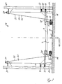
- FIGS. 1 and 2 show a gas storage 2 according to the invention with a variable-size gas space 4, the in Fig. 1 filled and in Fig. 2 is almost empty.
- the gas space 4 is bounded laterally by a flexible wall 6 with a cylindrical basic shape and on the upper side by a cover 8 connected in a gas-tight manner to the wall 6.
- On the underside, the gas space 4 is limited by a bottom 10. The filling of the gas space 4 with gas and the removal of gas via a recessed in the bottom 10 gas port 11th
- the wall 6 and the ceiling 8 are formed as movable parts, as from the comparison of FIGS. 1 and 2 is apparent.
- the extent of the wall 6 is bounded laterally by stabilizing elements 12.
- the stabilizing elements 12 are evenly distributed around the wall 6 around.
- Fig. 1 and 2 each of the left and the right side of the illustrated gas storage 2 are the same structure: Hereinafter, for the sake of simplicity, only one of the pages will be explained occasionally. However, the explanation applies equally to the other side of the gas storage 2.
- the stabilizing element 12 of each side is inherently flexible and is formed in the embodiment of a network.
- the gas storage 2 has in the in Fig. 1 and 2 illustrated embodiment on each side of the gas storage a clamping device, each with a pair of cooperating abutment 14, 16. A portion of the stabilizing element 12 is tensioned between the cooperating abutments 14, 16 by a tensile stress.
- the respective upper abutment 14 are fixedly connected to the ceiling as a movable part, whereas the lower abutment are not attached to one of the moving parts but at the bottom 18 outside the gas space 4 laterally adjacent to the wall 6.
- the lower abutment 16 are formed as deflection rollers 16.
- the tensioning device on each side urges the stabilizing element 12 with a tensile stress which is aligned substantially parallel to the wall 6 of the gas reservoir 2 in its gas-filled state.
- the wall 6 is formed by the tensioned nets 12 in the area between the abutments 14, 16 are prevented from expanding or shifting beyond the nets 12.
- the relative position of the wall 6 to the streamlined parts of the stabilizing elements 12 next to the wall 6 remains constant with a change in the size of the gas space 4.
- Wall 6 and this on an expansion outwardly limiting taut stabilizing element 12 perform during a change in size of the gas chamber 4, the same movement relative to the bottom 10 or 18.
- the tensioning device on each side has in each case a draw weight 20 which acts indirectly on the stabilizing element 12 for applying the tensile force via a tension element 22, the stabilizing element 12 being guided around the deflection roller 16.
- the draw weight 20 can also act directly on the stabilization element 12.
- the train weight can be formed by the ceiling itself, whereby the total weight and the required amount of material of the gas storage can be further reduced cost-reducing. Both aforementioned embodiments are not shown in the figures.
- the deflection rollers 16 are each associated with further deflection rollers 24 which are arranged further away from the base 18 than the respective first deflection roller 16.
- the stabilization element 12 is guided starting from its attachment to the ceiling 8 as a further abutment 14 around the respectively first deflection roller 16.
- the tension elements 22 are each connected via connecting means 26 with the stabilizing element 12 and are guided over the further deflection roller 24 up to the end-side draw weight 20, which is connected to the tension element 22.
- the ceiling 8 is pushed away on the one hand from the prevailing pressure in the gas chamber 4 operating pressure of about 50 millibar above the external pressure from the bottom 10. On the other hand, this pressure counteracts the weight of the blanket 8.
- the ceiling 8 is pulled over the stabilizing elements 12 and the tensile elements 22 acting thereon by the draw weights 20 in the direction of the bottom 10 of the gas space 4.
- the ceiling 8 operates with respect to the gas space 4 similar to a piston.
- the further deflection roller 24 is attached to a support 28 which is adjacent to the gas space 4.
- two struts 30 are arranged with end guide means 32 in the form of two rollers.
- the guide means 32 are movable along these associated and complementary to these trained guide rails 34.
- the guide rails 34 are arranged in the exemplary embodiment of the supports 28.
- two rollers are provided as a guide means 32 per strut.
- the struts 30 and the attached end-side rollers 32 are aligned with the ceiling 8 so that an unwanted inclination of the ceiling 8, for example, as a result of not uniformly running pulleys 16, 24, relative to the wall 6 is prevented.
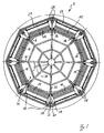
- Fig. 3 shows a further embodiment of a gas storage device 2 according to the invention in plan view.
- the gas storage 2 has eight stabilizing elements 12 and correspondingly eight first deflection rollers 16.
- the stabilizing elements 12 thus form in plan view essentially a uniform octagon. It has been found that good stabilization of the wall 6 can be achieved by this preferred embodiment. Of course, depending on the size and shape of the gas space 4, however, more or less stabilizing elements 12 may be provided.
- the deflection rollers 16 are each formed as rollers 16, around which in each case the stabilizing element 12 is guided.
- the rollers 16 each have a further deflection roller 24 is assigned, which is also formed in the embodiment as a roller 24.
- the further rollers 24 are each mounted between two supports 28.
- the gas storage 2 also has a substantially cylindrical wall 6 here.
- the gas storage 2 consists of an octagonal in plan view ceiling frame 36 and a ceiling membrane 38 which is connected to the gas-tight wall 6.
- the ceiling membrane 38 in Fig. 3 made transparent to indicate the underlying position of the wall 6 can.
- each struts 30 are mounted in extension of the ceiling frame 36, at which end the guide means 32 in the in Fig. 1 and 2 shown Sort are arranged.
- the guide means 32 are preferably formed in the form of two superimposed rollers.
- the guide means 32 are movable on guide rails 34, which are each arranged on the supports 28.
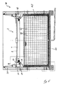
- Fig. 4 and 5 show a biogas plant 40 according to the invention with a fermentation tank 42 above which a gas storage 2 of the type described above is arranged.
- the gas storage 2 is gas-tightly connected to the fermentation tank 42 and in Fig. 4 fuller than in Fig. 5 ,
- the headspace of the fermentation tank 42 or the biogas plant 40 is formed by the gas storage 2.
- the gas space 4 of the gas storage 2 is limited downwards either from the bottom 44 or from a liquid in the fermentation tank, for example manure.
- a fermentation solution such as manure or manure, from the fermentation processes biogas, especially methane, is formed.
- the biogas is then stored in the gas storage 2 preferably under pressure.
- the supports 28 of the gas storage 2 are used simultaneously as supports of the fermentation tank 42. Between the supports 28 while a grid structure 46 is arranged, which is designed on the inside with a liquid-tight fermentation tank membrane 48.
- a grid structure 46 is arranged, which is designed on the inside with a liquid-tight fermentation tank membrane 48.
- the other abutment 16 can then be designed as deflection rollers fixed to the ceiling. As a result, it is possible to dispense with the further deflection rollers 24.
- Fig. 6 shows the magnification of the section A from Fig. 5
- the gas storage 2 has in principle the same elements, which are also in Fig. 1 and 2 are shown.
- the gas storage 2 is gas-tight connected to the fermentation tank 42.
Landscapes
- Health & Medical Sciences (AREA)
- Engineering & Computer Science (AREA)
- Life Sciences & Earth Sciences (AREA)
- Chemical & Material Sciences (AREA)
- Bioinformatics & Cheminformatics (AREA)
- Organic Chemistry (AREA)
- Zoology (AREA)
- Wood Science & Technology (AREA)
- General Engineering & Computer Science (AREA)
- Genetics & Genomics (AREA)
- Microbiology (AREA)
- Biomedical Technology (AREA)
- Biotechnology (AREA)
- Sustainable Development (AREA)
- Biochemistry (AREA)
- General Health & Medical Sciences (AREA)
- Molecular Biology (AREA)
- Clinical Laboratory Science (AREA)
- Mechanical Engineering (AREA)
- Oil, Petroleum & Natural Gas (AREA)
- General Chemical & Material Sciences (AREA)
- Filling Or Discharging Of Gas Storage Vessels (AREA)
Claims (14)
- Réservoir de gaz (2), avec une chambre de gaz (4) de taille variable qui est délimitée au moins par secteur par une paroi souple (6) et un plafond (8) sous forme de pièces mobiles, avec au moins un élément de stabilisation (12) souple délimitant au moins par secteur l'extension de la paroi (6) et avec au moins un dispositif de tension avec au moins une paire de contre-appuis coopérants (14, 16) entre lesquels au moins une partie de l'élément de stabilisation (12) est tendue par un effort de traction, dans lequel seul l'un des contre-appuis respectivement coopérants (14, 16) est relié solidement à l'une des pièces mobiles (6, 8), caractérisé en ce que le premier contre-appui de la paire de contre-appuis coopérants (14, 16) est formé par une poulie de renvoi (16) et le dispositif de tension par poulie de renvoi (16) présente au moins une autre poulie de renvoi (24) autour de laquelle l'élément de stabilisation (12) est guidé directement ou indirectement par le biais d'un élément de traction (22) venant en prise sur l'élément de stabilisation (12), dans lequel l'autre poulie de renvoi (24) est plus éloignée du sol (10) que la première poulie de renvoi (16).
- Réservoir de gaz (2) selon la revendication 1, caractérisé en ce que l'élément de stabilisation (12) est un filet, un câble, un tissu, un film ou similaire ou une combinaison de deux ou plusieurs de ces éléments.
- Réservoir de gaz (2) selon l'une quelconque des revendications précédentes, caractérisé en ce que le dispositif de tension sollicite l'élément de stabilisation (12) par un effort de traction essentiellement parallèle à la paroi (6) du réservoir de gaz (2).
- Réservoir de gaz (2) selon l'une quelconque des revendications précédentes, caractérisé en ce que le dispositif de tension présente au moins un poids de traction (20) qui vient en prise sur l'élément de stabilisation (12) directement ou indirectement par le biais d'un élément de traction (22) pour l'application de l'effort de traction, dans lequel l'élément de stabilisation (12) ou l'élément de traction (22) est guidé autour de la poulie de renvoi (16).
- Réservoir de gaz (2) selon l'une quelconque des revendications précédentes, caractérisé en ce que l'autre contre-appui (14) de la paire de contre-appuis coopérants (14, 16) est fixé au plafond (8) et la poulie de renvoi (16) est disposée sous l'autre contre-appui (14).
- Réservoir de gaz (2) selon l'une quelconque des revendications précédentes, caractérisé en ce que l'autre poulie de renvoi (24) est fixée à un support (28).
- Réservoir de gaz (2) selon l'une quelconque des revendications précédentes, caractérisé en ce que la première poulie de renvoi (16) est un cylindre autour duquel l'élément de stabilisation (12) est guidé.
- Réservoir de gaz (2) selon l'une quelconque des revendications 1 à 6, caractérisé en ce que le réservoir de gaz (2) présente huit éléments de stabilisation (12) et huit premières poulies de renvoi (16).
- Réservoir de gaz (2) selon la revendication 8, caractérisé en ce que le réservoir de gaz (2) présente huit supports (28) et huit autres poulies de renvoi (24).
- Réservoir de gaz (2) selon l'une quelconque des revendications précédentes, caractérisé en ce que le plafond (8) présente au moins une fixation pour des poids supplémentaires.
- Réservoir de gaz (2) selon l'une quelconque des revendications précédentes, caractérisé en ce qu'au moins deux entretoises (30) avec des moyens de guidage (32) côté extrémité, qui sont déplaçables verticalement le long de rails de guidage (34) respectivement affectés et réalisés de manière complémentaire aux moyens de guidage (32), sont disposés au niveau du plafond (8).
- Réservoir de gaz (2) selon l'une quelconque des revendications précédentes, caractérisé par au moins une aide au plissage reliée à la paroi (6) ou réalisée comme une partie de la paroi (6) pour un plissage régulier de la paroi (6) lors d'une réduction de la taille de la chambre de gaz (4).
- Installation de biogaz (40) permettant de produire du biogaz, en particulier du méthane, avec un fermenteur (42) et un réservoir de gaz (2) selon l'une quelconque des revendications précédentes, qui est relié au fermenteur (42) de manière étanche aux gaz.
- Installation de biogaz (40) selon la revendication 13, caractérisée en ce que le réservoir de gaz (2) est disposé au-dessus du fermenteur (42).
Priority Applications (1)
| Application Number | Priority Date | Filing Date | Title |
|---|---|---|---|
| PL07818143T PL2061987T3 (pl) | 2006-09-15 | 2007-09-13 | Zbiornik gazu oraz instalacja biogazowa ze zbiornikiem gazu |
Applications Claiming Priority (2)
| Application Number | Priority Date | Filing Date | Title |
|---|---|---|---|
| DE202006014148U DE202006014148U1 (de) | 2006-09-15 | 2006-09-15 | Gasspeicher sowie Biogasanlage mit einem Gasspeicher |
| PCT/EP2007/007980 WO2008031593A1 (fr) | 2006-09-15 | 2007-09-13 | Réservoir de gaz et installation de biogaz munie d'un réservoir de gaz |
Publications (2)
| Publication Number | Publication Date |
|---|---|
| EP2061987A1 EP2061987A1 (fr) | 2009-05-27 |
| EP2061987B1 true EP2061987B1 (fr) | 2012-10-31 |
Family
ID=37650849
Family Applications (1)
| Application Number | Title | Priority Date | Filing Date |
|---|---|---|---|
| EP07818143A Not-in-force EP2061987B1 (fr) | 2006-09-15 | 2007-09-13 | Reservoir de gaz et installation de biogaz munie d'un reservoir de gaz |
Country Status (4)
| Country | Link |
|---|---|
| EP (1) | EP2061987B1 (fr) |
| DE (1) | DE202006014148U1 (fr) |
| PL (1) | PL2061987T3 (fr) |
| WO (1) | WO2008031593A1 (fr) |
Families Citing this family (9)
| Publication number | Priority date | Publication date | Assignee | Title |
|---|---|---|---|---|
| DE202006014149U1 (de) * | 2006-09-15 | 2007-01-04 | Reinelt, Gerhard | Gärbehälter sowie Biogasanlage mit einem Gärbehälter |
| CN102410439B (zh) * | 2011-11-16 | 2013-10-30 | 中冶南方工程技术有限公司 | 一种橡胶膜辅助提升装置 |
| CN102759011A (zh) * | 2012-07-30 | 2012-10-31 | 中冶南方工程技术有限公司 | 煤气柜密封装置的加力机构 |
| DE102012023033A1 (de) | 2012-11-26 | 2014-05-28 | S+B Service Und Betrieb Gmbh | Vorrichtung zur gasdichten Abdeckung von Lagerbehältern ohne Innenstütze |
| WO2014079401A1 (fr) * | 2012-11-26 | 2014-05-30 | S+B Service Und Betrieb Gmbh | Dispositif de recouvrement étanche aux gaz de réservoirs de stockage sans support intérieur |
| CN103499012B (zh) * | 2013-10-10 | 2015-08-26 | 福建省农业科学院农业工程技术研究所 | 玻璃钢沼气储气柜 |
| DE102016106042B4 (de) | 2016-04-01 | 2025-10-02 | PROMEDIA Gesundheitspartner GmbH | Antriebsmittel für Mikronadelvorrichtung in Stift-Form |
| CN108929847A (zh) * | 2018-08-23 | 2018-12-04 | 福建省农业科学院农业工程技术研究所 | 组合式沼气储气柜及其使用方法 |
| NL2031650B1 (en) * | 2022-04-21 | 2023-11-07 | The Waste Transf Investments B V | An energy or gas generation plant |
Family Cites Families (4)
| Publication number | Priority date | Publication date | Assignee | Title |
|---|---|---|---|---|
| FR680304A (fr) | 1928-08-15 | 1930-04-28 | Bamag Meguin Ag | Gazomètre à cloche mobile sans liquide d'étanchéité |
| DE3735208A1 (de) * | 1987-10-17 | 1989-04-27 | Xaver Lipp | Speicheranlage fuer gasfoermige medien niedrigen druckes |
| DE20208171U1 (de) | 2002-05-24 | 2002-09-05 | FORTUNA Landmaschinen GmbH & Co. KG Bernhard Schwartbeck, 48607 Ochtrup | Halterung für das Ende mindestens einer Luft- oder Hydraulik- oder Elektroverbindungsleitung |
| DE20208178U1 (de) * | 2002-05-29 | 2002-09-26 | Kassen, Dirk, 49124 Georgsmarienhütte | Gasbehälter |
-
2006
- 2006-09-15 DE DE202006014148U patent/DE202006014148U1/de not_active Expired - Lifetime
-
2007
- 2007-09-13 EP EP07818143A patent/EP2061987B1/fr not_active Not-in-force
- 2007-09-13 WO PCT/EP2007/007980 patent/WO2008031593A1/fr not_active Ceased
- 2007-09-13 PL PL07818143T patent/PL2061987T3/pl unknown
Also Published As
| Publication number | Publication date |
|---|---|
| WO2008031593A1 (fr) | 2008-03-20 |
| DE202006014148U1 (de) | 2006-12-28 |
| PL2061987T3 (pl) | 2013-03-29 |
| EP2061987A1 (fr) | 2009-05-27 |
Similar Documents
| Publication | Publication Date | Title |
|---|---|---|
| EP2061987A1 (fr) | Réservoir de gaz et installation de biogaz munie d'un réservoir de gaz | |
| EP2270128B1 (fr) | Installation de biogaz et élement de regard pour une installation de biogaz | |
| EP2586658B2 (fr) | Caisse de véhicule pour le transport de marchandises de transport empilables ou coulables | |
| EP0106857B1 (fr) | Couverture flexible d'un accumulateur de gaz | |
| EP1744976A2 (fr) | Dispositif de transport a bande transporteuse | |
| EP4005839B1 (fr) | Bâche à précontrainte pouvant être ajustée et bandes de maintien en tant que protection contre les coupures et les surcharges mécaniques | |
| DE102012006745B4 (de) | Scherenhubtisch | |
| WO1985004154A1 (fr) | Cadres pour installations de transport a bande | |
| DE19701415C1 (de) | Vorrichtung zum Breithalten und Quetschen von Schlauch-Wirkware | |
| DE4232318A1 (de) | Gasdichter Silo | |
| EP3245148A1 (fr) | Système de transport à mécanisme à rouleaux | |
| EP2708393B1 (fr) | Caisse de véhicule pour le transport de marchandises de transport empilables ou coulables | |
| DE3427742A1 (de) | Hebeeinrichtung mit scherengestaenge und flaschenzug | |
| DE102007008916B4 (de) | Aufnahmevorrichtung für Paletten und Nutzfahrzeug mit einer derartigen Vorrichtung | |
| DE19513145A1 (de) | Wehreinrichtung | |
| EP2230196A1 (fr) | Dispositif de stockage pour matière en vrac | |
| EP1427637A2 (fr) | Tulipe de prise destinee a la prise cote tete de bouteilles notamment fermees au moyen de bouchons en lieges, de bouchons a couronne, de bouchons visses ou de bouchons mecaniques | |
| EP1515863B1 (fr) | Dispositif de serrage fluidique | |
| DE2518061C2 (de) | Tragrahmen | |
| DE1923430A1 (de) | Flexible Schuerze fuer Bodeneffektmaschinen | |
| DE102018102752A1 (de) | Heber mit mindestens einer vertikal verfahrbaren Hubplattform mit einem Riemenantrieb | |
| EP2346752B1 (fr) | Dispositif de stabilisation de la position de contenants remplis de matieres de consistance fluide en conteneurs normalises | |
| DE10208343B4 (de) | Packtulpe zum kopfseitigen Ergreifen von insbesondere durch Korken, Kron-, Schraub- oder Bügelverschluß verschließbaren Flaschen | |
| EP2778318B1 (fr) | Dispositif de recouvrement ou de couverture d'une surface de base, d'une structure formant une pièce ou d'une machine | |
| DE2849726C2 (de) | Filterpresse mit Spreiztuch-Einrichtung |
Legal Events
| Date | Code | Title | Description |
|---|---|---|---|
| PUAI | Public reference made under article 153(3) epc to a published international application that has entered the european phase |
Free format text: ORIGINAL CODE: 0009012 |
|
| 17P | Request for examination filed |
Effective date: 20090403 |
|
| AK | Designated contracting states |
Kind code of ref document: A1 Designated state(s): AT BE BG CH CY CZ DE DK EE ES FI FR GB GR HU IE IS IT LI LT LU LV MC MT NL PL PT RO SE SI SK TR |
|
| AX | Request for extension of the european patent |
Extension state: AL BA HR MK RS |
|
| 17Q | First examination report despatched |
Effective date: 20100316 |
|
| GRAP | Despatch of communication of intention to grant a patent |
Free format text: ORIGINAL CODE: EPIDOSNIGR1 |
|
| RIC1 | Information provided on ipc code assigned before grant |
Ipc: F17B 1/26 20060101AFI20120504BHEP Ipc: C12M 1/107 20060101ALI20120504BHEP |
|
| DAX | Request for extension of the european patent (deleted) | ||
| GRAS | Grant fee paid |
Free format text: ORIGINAL CODE: EPIDOSNIGR3 |
|
| GRAA | (expected) grant |
Free format text: ORIGINAL CODE: 0009210 |
|
| AK | Designated contracting states |
Kind code of ref document: B1 Designated state(s): AT BE BG CH CY CZ DE DK EE ES FI FR GB GR HU IE IS IT LI LT LU LV MC MT NL PL PT RO SE SI SK TR |
|
| REG | Reference to a national code |
Ref country code: GB Ref legal event code: FG4D Free format text: NOT ENGLISH Ref country code: CH Ref legal event code: EP |
|
| REG | Reference to a national code |
Ref country code: AT Ref legal event code: REF Ref document number: 582221 Country of ref document: AT Kind code of ref document: T Effective date: 20121115 |
|
| REG | Reference to a national code |
Ref country code: IE Ref legal event code: FG4D Free format text: LANGUAGE OF EP DOCUMENT: GERMAN |
|
| REG | Reference to a national code |
Ref country code: DE Ref legal event code: R096 Ref document number: 502007010818 Country of ref document: DE Effective date: 20121227 |
|
| REG | Reference to a national code |
Ref country code: LT Ref legal event code: MG4D |
|
| REG | Reference to a national code |
Ref country code: PL Ref legal event code: T3 |
|
| REG | Reference to a national code |
Ref country code: NL Ref legal event code: VDEP Effective date: 20121031 |
|
| PG25 | Lapsed in a contracting state [announced via postgrant information from national office to epo] |
Ref country code: NL Free format text: LAPSE BECAUSE OF FAILURE TO SUBMIT A TRANSLATION OF THE DESCRIPTION OR TO PAY THE FEE WITHIN THE PRESCRIBED TIME-LIMIT Effective date: 20121031 Ref country code: IS Free format text: LAPSE BECAUSE OF FAILURE TO SUBMIT A TRANSLATION OF THE DESCRIPTION OR TO PAY THE FEE WITHIN THE PRESCRIBED TIME-LIMIT Effective date: 20130228 Ref country code: LT Free format text: LAPSE BECAUSE OF FAILURE TO SUBMIT A TRANSLATION OF THE DESCRIPTION OR TO PAY THE FEE WITHIN THE PRESCRIBED TIME-LIMIT Effective date: 20121031 Ref country code: FI Free format text: LAPSE BECAUSE OF FAILURE TO SUBMIT A TRANSLATION OF THE DESCRIPTION OR TO PAY THE FEE WITHIN THE PRESCRIBED TIME-LIMIT Effective date: 20121031 Ref country code: SE Free format text: LAPSE BECAUSE OF FAILURE TO SUBMIT A TRANSLATION OF THE DESCRIPTION OR TO PAY THE FEE WITHIN THE PRESCRIBED TIME-LIMIT Effective date: 20121031 Ref country code: ES Free format text: LAPSE BECAUSE OF FAILURE TO SUBMIT A TRANSLATION OF THE DESCRIPTION OR TO PAY THE FEE WITHIN THE PRESCRIBED TIME-LIMIT Effective date: 20130211 |
|
| PG25 | Lapsed in a contracting state [announced via postgrant information from national office to epo] |
Ref country code: SI Free format text: LAPSE BECAUSE OF FAILURE TO SUBMIT A TRANSLATION OF THE DESCRIPTION OR TO PAY THE FEE WITHIN THE PRESCRIBED TIME-LIMIT Effective date: 20121031 Ref country code: LV Free format text: LAPSE BECAUSE OF FAILURE TO SUBMIT A TRANSLATION OF THE DESCRIPTION OR TO PAY THE FEE WITHIN THE PRESCRIBED TIME-LIMIT Effective date: 20121031 Ref country code: GR Free format text: LAPSE BECAUSE OF FAILURE TO SUBMIT A TRANSLATION OF THE DESCRIPTION OR TO PAY THE FEE WITHIN THE PRESCRIBED TIME-LIMIT Effective date: 20130201 Ref country code: CY Free format text: LAPSE BECAUSE OF FAILURE TO SUBMIT A TRANSLATION OF THE DESCRIPTION OR TO PAY THE FEE WITHIN THE PRESCRIBED TIME-LIMIT Effective date: 20121031 Ref country code: PT Free format text: LAPSE BECAUSE OF FAILURE TO SUBMIT A TRANSLATION OF THE DESCRIPTION OR TO PAY THE FEE WITHIN THE PRESCRIBED TIME-LIMIT Effective date: 20130228 |
|
| PG25 | Lapsed in a contracting state [announced via postgrant information from national office to epo] |
Ref country code: SK Free format text: LAPSE BECAUSE OF FAILURE TO SUBMIT A TRANSLATION OF THE DESCRIPTION OR TO PAY THE FEE WITHIN THE PRESCRIBED TIME-LIMIT Effective date: 20121031 Ref country code: CZ Free format text: LAPSE BECAUSE OF FAILURE TO SUBMIT A TRANSLATION OF THE DESCRIPTION OR TO PAY THE FEE WITHIN THE PRESCRIBED TIME-LIMIT Effective date: 20121031 Ref country code: BG Free format text: LAPSE BECAUSE OF FAILURE TO SUBMIT A TRANSLATION OF THE DESCRIPTION OR TO PAY THE FEE WITHIN THE PRESCRIBED TIME-LIMIT Effective date: 20130131 Ref country code: DK Free format text: LAPSE BECAUSE OF FAILURE TO SUBMIT A TRANSLATION OF THE DESCRIPTION OR TO PAY THE FEE WITHIN THE PRESCRIBED TIME-LIMIT Effective date: 20121031 Ref country code: EE Free format text: LAPSE BECAUSE OF FAILURE TO SUBMIT A TRANSLATION OF THE DESCRIPTION OR TO PAY THE FEE WITHIN THE PRESCRIBED TIME-LIMIT Effective date: 20121031 |
|
| PG25 | Lapsed in a contracting state [announced via postgrant information from national office to epo] |
Ref country code: RO Free format text: LAPSE BECAUSE OF FAILURE TO SUBMIT A TRANSLATION OF THE DESCRIPTION OR TO PAY THE FEE WITHIN THE PRESCRIBED TIME-LIMIT Effective date: 20121031 |
|
| PLBE | No opposition filed within time limit |
Free format text: ORIGINAL CODE: 0009261 |
|
| STAA | Information on the status of an ep patent application or granted ep patent |
Free format text: STATUS: NO OPPOSITION FILED WITHIN TIME LIMIT |
|
| 26N | No opposition filed |
Effective date: 20130801 |
|
| REG | Reference to a national code |
Ref country code: DE Ref legal event code: R097 Ref document number: 502007010818 Country of ref document: DE Effective date: 20130801 |
|
| BERE | Be: lapsed |
Owner name: REINELT, GERHARD Effective date: 20130930 |
|
| PG25 | Lapsed in a contracting state [announced via postgrant information from national office to epo] |
Ref country code: MC Free format text: LAPSE BECAUSE OF FAILURE TO SUBMIT A TRANSLATION OF THE DESCRIPTION OR TO PAY THE FEE WITHIN THE PRESCRIBED TIME-LIMIT Effective date: 20121031 |
|
| REG | Reference to a national code |
Ref country code: CH Ref legal event code: PL |
|
| GBPC | Gb: european patent ceased through non-payment of renewal fee |
Effective date: 20130913 |
|
| REG | Reference to a national code |
Ref country code: DE Ref legal event code: R119 Ref document number: 502007010818 Country of ref document: DE Effective date: 20140401 |
|
| REG | Reference to a national code |
Ref country code: FR Ref legal event code: ST Effective date: 20140530 |
|
| REG | Reference to a national code |
Ref country code: IE Ref legal event code: MM4A |
|
| PG25 | Lapsed in a contracting state [announced via postgrant information from national office to epo] |
Ref country code: BE Free format text: LAPSE BECAUSE OF NON-PAYMENT OF DUE FEES Effective date: 20130930 Ref country code: GB Free format text: LAPSE BECAUSE OF NON-PAYMENT OF DUE FEES Effective date: 20130913 Ref country code: LI Free format text: LAPSE BECAUSE OF NON-PAYMENT OF DUE FEES Effective date: 20130930 Ref country code: IE Free format text: LAPSE BECAUSE OF NON-PAYMENT OF DUE FEES Effective date: 20130913 Ref country code: CH Free format text: LAPSE BECAUSE OF NON-PAYMENT OF DUE FEES Effective date: 20130930 |
|
| PG25 | Lapsed in a contracting state [announced via postgrant information from national office to epo] |
Ref country code: DE Free format text: LAPSE BECAUSE OF NON-PAYMENT OF DUE FEES Effective date: 20140401 Ref country code: IT Free format text: LAPSE BECAUSE OF NON-PAYMENT OF DUE FEES Effective date: 20130913 Ref country code: FR Free format text: LAPSE BECAUSE OF NON-PAYMENT OF DUE FEES Effective date: 20130930 |
|
| REG | Reference to a national code |
Ref country code: AT Ref legal event code: MM01 Ref document number: 582221 Country of ref document: AT Kind code of ref document: T Effective date: 20130913 |
|
| PG25 | Lapsed in a contracting state [announced via postgrant information from national office to epo] |
Ref country code: PL Free format text: LAPSE BECAUSE OF NON-PAYMENT OF DUE FEES Effective date: 20130913 |
|
| REG | Reference to a national code |
Ref country code: PL Ref legal event code: LAPE |
|
| PG25 | Lapsed in a contracting state [announced via postgrant information from national office to epo] |
Ref country code: AT Free format text: LAPSE BECAUSE OF NON-PAYMENT OF DUE FEES Effective date: 20130913 |
|
| PG25 | Lapsed in a contracting state [announced via postgrant information from national office to epo] |
Ref country code: TR Free format text: LAPSE BECAUSE OF FAILURE TO SUBMIT A TRANSLATION OF THE DESCRIPTION OR TO PAY THE FEE WITHIN THE PRESCRIBED TIME-LIMIT Effective date: 20121031 Ref country code: MT Free format text: LAPSE BECAUSE OF FAILURE TO SUBMIT A TRANSLATION OF THE DESCRIPTION OR TO PAY THE FEE WITHIN THE PRESCRIBED TIME-LIMIT Effective date: 20121031 |
|
| PG25 | Lapsed in a contracting state [announced via postgrant information from national office to epo] |
Ref country code: HU Free format text: LAPSE BECAUSE OF FAILURE TO SUBMIT A TRANSLATION OF THE DESCRIPTION OR TO PAY THE FEE WITHIN THE PRESCRIBED TIME-LIMIT; INVALID AB INITIO Effective date: 20070913 Ref country code: LU Free format text: LAPSE BECAUSE OF NON-PAYMENT OF DUE FEES Effective date: 20130913 |