EP2062761A2 - Klimaanlage für ein Kraftfahrzeug - Google Patents
Klimaanlage für ein Kraftfahrzeug Download PDFInfo
- Publication number
- EP2062761A2 EP2062761A2 EP08020504A EP08020504A EP2062761A2 EP 2062761 A2 EP2062761 A2 EP 2062761A2 EP 08020504 A EP08020504 A EP 08020504A EP 08020504 A EP08020504 A EP 08020504A EP 2062761 A2 EP2062761 A2 EP 2062761A2
- Authority
- EP
- European Patent Office
- Prior art keywords
- bottom wall
- parting line
- air conditioning
- conditioning system
- housing
- Prior art date
- Legal status (The legal status is an assumption and is not a legal conclusion. Google has not performed a legal analysis and makes no representation as to the accuracy of the status listed.)
- Granted
Links
Images


Classifications
-
- B—PERFORMING OPERATIONS; TRANSPORTING
- B60—VEHICLES IN GENERAL
- B60H—ARRANGEMENTS OF HEATING, COOLING, VENTILATING OR OTHER AIR-TREATING DEVICES SPECIALLY ADAPTED FOR PASSENGER OR GOODS SPACES OF VEHICLES
- B60H1/00—Heating, cooling or ventilating devices
- B60H1/00507—Details, e.g. mounting arrangements, desaeration devices
- B60H1/00514—Details of air conditioning housings
- B60H1/00528—Connections between housing parts
-
- B—PERFORMING OPERATIONS; TRANSPORTING
- B60—VEHICLES IN GENERAL
- B60H—ARRANGEMENTS OF HEATING, COOLING, VENTILATING OR OTHER AIR-TREATING DEVICES SPECIALLY ADAPTED FOR PASSENGER OR GOODS SPACES OF VEHICLES
- B60H1/00—Heating, cooling or ventilating devices
- B60H1/32—Cooling devices
- B60H1/3233—Cooling devices characterised by condensed liquid drainage means
-
- B—PERFORMING OPERATIONS; TRANSPORTING
- B60—VEHICLES IN GENERAL
- B60H—ARRANGEMENTS OF HEATING, COOLING, VENTILATING OR OTHER AIR-TREATING DEVICES SPECIALLY ADAPTED FOR PASSENGER OR GOODS SPACES OF VEHICLES
- B60H1/00—Heating, cooling or ventilating devices
- B60H1/00507—Details, e.g. mounting arrangements, desaeration devices
- B60H2001/00635—Air-tight sealing devices
Definitions
- the invention relates to an air conditioning system for a motor vehicle, comprising a housing at least partially formed by a left and right housing part for receiving a refrigerant evaporator, wherein between the left and right housing part a parting line occurs, arranged in the housing a refrigerant evaporator, a bottom wall formed by the housing Collecting the condensate water forming at the refrigerant evaporator and at least one drainage opening arranged in the bottom wall for discharging the condensed water formed at the refrigerant evaporator.
- the invention further relates to an air conditioning system for a motor vehicle, comprising a housing at least partially formed by a left and right housing part for receiving a refrigerant evaporator, wherein between the left and right housing part at least one parting line occurs, a sealing means for sealing the parting line, arranged in the housing Refrigerant evaporator, a bottom wall for collecting the condensate forming at Käfteffenverdampfer and at least one arranged in the bottom wall drain opening for discharging the condensate formed at the refrigerant evaporator.
- Component of air conditioning systems for motor vehicles form HVAC plastic housing with a refrigerant evaporator for cooling and a heater for heating an air to be led into the interior of the motor vehicle.
- the housings can provide a separation into an upper and a lower housing part or into a left and a right housing part, so that the housing consists of two components. Furthermore, a separation in a left lower, a right lower and an upper housing part may be formed. Between the housing parts forms a parting line. At the refrigerant evaporator condensation condenses, which is collected on the bottom wall of the housing and passed through a drain opening from the housing.
- Housing with a separation only in an upper and lower housing part do not have a parting line in the area of the applied with condensed water bottom wall, so that no sealing problems can occur because of the condensation on the parting line.
- a parting line occurs on the bottom wall formed by the housing, which must be sealed.
- Housing with a separation into a right and left housing part have the advantage that they are generally smaller and more compact.
- an insert in the region of the bottom wall can be used.
- the measures for sealing the parting line are complicated and expensive. Nevertheless, leaks, z. B. in a shrinkage of the elastic seal occur.
- the housing consists of a left and right Housing part.
- the two housing parts are connected to each other by means of a tongue and groove connection.
- an elastic seal is arranged in the tongue and groove connection. Through a drain opening, the condensation is directed out of the housing.
- z At the tongue and groove connection, z. As in tolerance deviations in manufacturing, leaks occur and the seal and its installation is complicated and expensive.
- the object of the present invention is therefore to allow for an air conditioning system with a separation in a left and right housing a safe and reliable sealing of the parting line in the acted upon with condensed water bottom wall.
- the air conditioning should be ensured in the production of simple and inexpensive as well as in case of deviations in the manufacturing tolerance of the housing parts a trouble seal.
- an air conditioning system for a motor vehicle comprising a housing at least partially formed by a left and right housing part for receiving a refrigerant evaporator, wherein between the left and right housing part, a parting line occurs, disposed in the housing refrigerant evaporator, one formed by the housing Bottom wall for collecting the condensate forming on the refrigerant evaporator and at least one drain opening arranged in the bottom wall for discharging the condensate formed at the refrigerant evaporator, wherein the separating gap is arranged exclusively above the drain opening on the bottom wall.
- the parting line is thus applied only with Schwellwasser and not with stagnant water.
- Standing water can occur, for example, on the bottom wall, if the drain hole is partially blocked or, for. As in shakings, in the short term, a larger amount of condensation from the refrigerant evaporator falling on the bottom wall. Furthermore, there is a gradient between the parting line and the drainage opening, so that the condensate does not stand at the parting line, but flows.
- the design of the process is typically carried out so that about half a liter of water can drain in about 15 seconds.
- the parting line preferably in the vertical direction, is arranged more than 0.5 cm, in particular more than 1 cm, exclusively above the discharge opening.
- the inclination of the bottom wall is directed in a direction perpendicular to the plane of the parting line on both sides of the parting line down to at least one drain opening, in particular with a slope of more than 17 °.
- the bottom wall on both sides of the parting line is either uniformly inclined to an outlet opening or oppositely inclined, d. H. designed as a roof profile, each inclined to a drain opening.
- the parting line is arranged in the region of a maximum height of the bottom wall.
- the parting line is thus formed in a region of a maximum height of the bottom wall, so that the condensation on both sides of the parting line runs in the opposite direction.
- the parting line is formed in a bottom wall inclined only in one direction to the discharge opening, preferably centrally, between a region of a minimum height of the bottom wall, in particular with the discharge opening, and a region of a maximum height of the bottom wall.
- the condensation water impinging on the bottom wall runs in the same direction to the discharge opening on both sides of the parting line.
- the parting line is covered by a sealing rib and / or a clamping profile.
- the condensation can not impinge directly from above directly on the parting line, so that a short-term water pressure on the parting line, caused by an incident directly on the parting line condensate drops, can not occur.
- the sealing rib is fixed to a housing part.
- the sealing rib is formed integrally with the one housing part.
- the sealing rib can thus be produced, for example, simply during injection molding of the housing part on the bottom wall.
- the sealing rib is thus made of the same material as the housing.
- the sealing rib preferably consists of an elastomeric material and is in particular produced by means of the technique of two-component injection molding in one piece with the housing.
- the sealing rib extends from a higher portion of the bottom wall to a lower portion of the bottom wall and the sealing rib is formed integrally with the higher portion of the bottom wall. The condensation water thus passes from the higher lying portion of the bottom wall on the sealing rib to the lower portion of the bottom wall.
- one end of the sealing rib is designed as a drip nose and the drip nose covers the parting line at a distance.
- the drip nose causes condensed water drops to fall in a controlled manner at a distance from the parting line to the bottom wall.
- the parting line is thereby increased, so that the condensation prevents a greater flow resistance to flow through the parting line.
- the additional sealing rib is formed integrally with the other housing part.
- both sealing ribs are enclosed by a shrink tube or a shrink film or a clamping profile.
- the shrink tubing or the shrink film thus additionally seal the parting line.
- the clamping profile presses both sealing ribs against each other and / or additionally seals the parting line.
- the parting line is formed by a tongue and groove joint.
- the tongue and groove connection allows a positive connection between the two housing parts.
- a protruding sealing lip which is enclosed by a heat-shrinkable tube or a shrink-wrap film or a clamping profile, is formed on each of the housing parts on a underside of the bottom wall which is not subjected to condensation.
- the shrink tubing or the shrink film or the clamping profile thus additionally seal the parting line at the bottom.
- the clamping profile preferably presses both projecting sealing lips together.
- the tongue and groove connection is at least partially disposed in the sealing lip.
- an emergency drainage channel is enclosed by the clamping profile and / or a shrinking tube or a shrinking film. Condensation water can preferably be conducted from the emergency drainage channel into a condensation drainage.
- the emergency gutter is formed by an elongated recess in a sealing lip. The emergency gutter is preferably formed on the underside of the bottom wall.
- the elastic clamping profile presses the left and right housing part against each other at the parting line, for example by the clamping profile enclosing the sealing rib and the additional rib or both sealing lips.
- the elastic clamping profile is arranged between the left and right housing part, so that the clamping profile seals the parting line.
- the at least one drain opening is formed at a low point of the bottom wall.
- a heating device and / or a filter and / or an electrical afterheating and / or a baffle wall and / or at least one air flap and / or a fan are arranged in the housing.
- the sealant forms the drain opening.
- the sealing means preferably in one piece, forms a connecting piece.
- the connection piece can be easily performed elastic.
- the at least one parting line is formed by a tongue and groove joint.
- the sealing means is an elastic sealing element.
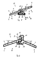
- FIG. 1 shows a cross section of a housing 1 for an air conditioning system of a motor vehicle (not shown).
- the housing 1 consists of a left housing part 2 and a right housing part 3 (in Fig. 2, 3 and 4 partially shown). Between the left and right housing part 2, 3 thus forms a parting line 4 (in Fig. 1 not shown). The plane of the parting line 4 is vertically aligned.
- the remaining components of the air conditioning, z As a refrigerant condenser and a compressor are not shown.
- the housing 1 accommodates a blower 23, a filter 20, a refrigerant evaporator 5, a heating device 6 through which the cooling water of the engine flows, and an electric reheater 22.
- the air for the passenger compartment is guided by the blower 23 through the filter 20 and the refrigerant evaporator 5. Due to the cooling of the air flow in the refrigerant evaporator 5, the moisture contained in the air flow at the refrigerant evaporator 5 settles down and condensation drops form on the refrigerant evaporator 5.
- the condensate drops fall from a certain size due to gravity on a bottom wall 7 formed by the housing 1 and collect here. At higher air flow rates, condensate drops can also be entrained by the air flow in the direction of the heating device 6.
- a baffle 21 serves to retain the condensed water droplets entrained by the air flow and to guide them in the direction of the bottom wall 7.
- air dampers control the proportion of the air flow, which is passed after flowing through the refrigerant evaporator 5 by the heater 6 and / or the electric reheater 22.
- the heated and / or cooled air leaves the housing 1 through an outlet opening 24.
- the bottom wall 7, which is to be formed watertight, is in Fig. 1 framed with a dot-dash box.
- Fig. 2 to 4 is a cross section of the bottom wall 7 shown in three embodiments.
- Fig. 2 is the bottom wall 7 below the refrigerant evaporator 5 uniformly inclined from left to right.
- the parting line 4 is centrally located between the minimum height 9 and the maximum height 10 of the bottom wall 7.
- the condensate collecting on the bottom wall 7 flows in accordance with the slope of the bottom wall 7 to the vertical drain opening 8 and flows through the drain opening 8 from the housing 1.
- the drain opening 8 can also be made horizontal (not shown).
- the parting line 4 between the left and right housing part 2, 3 is thus not subjected to standing condensation, but only with sump water, because the condensation on the parting line 4 flows down only.
- Separate sealants eg. As an elastic seal, are therefore not required for sealing the parting line 4.
- the bottom wall 7 is formed as a roof profile.
- the area with a maximum height 10 is formed centrally between two areas with a minimum height 9 of the bottom wall 7.
- the condensate flows through two horizontal restructuringöffinept 8 of the housing 1, which are executed at the minimum height 9 of the bottom wall 7.
- the drain openings 8 may also be formed vertically (not shown).
- the parting line 4 is located at the area with the maximum height 10 of the bottom wall 7, so that no stagnant water, but only Schwelligan occurs at the parting line 4.
- a third embodiment is in Fig. 4 the bottom wall 7 in four sections 25, 26, 27, 28 divided.
- the two inner portions 25, 26 are formed as a roof profile on which in each case a further section 27, 28th the bottom wall 7 connects with a uniform inclination.
- the parting line 4 is located at the maximum height 10 of the bottom wall 7 between the two inner portions 25, 26 of the bottom wall 7.
- the two vertical discharge openings 8 are each between the outer portion 27, 28 and an adjoining inner portion 25, 26 are arranged.
- the drain openings 8 can also be formed horizontally (not shown). Thus occurs at the parting line 4 only threshold water and no stagnant water.
- the bottom wall 7 has perpendicular to the plane above a slope, so that the condensation can flow to the perpendicular to the plane only locally arranged drain holes 8.
- Fig. 5 to 11 show in detail the formation of the parting line 4 as a tongue and groove joint 18th
- Fig. 5 shows the parting line 4 for the bottom wall 7 according to Fig. 2
- a sealing rib 11 is provided, which is made in one piece on the higher-lying portion 12 of the bottom wall 7 and the parting line 4 overlaps.
- the sealing rib 11 rests on the lower portion 13 of the bottom wall 7.
- the condensate flows on the upper side 29 of the bottom wall 7 from the higher lying portion 12 of the bottom wall 7 via the sealing rib 11 to the deeper portion 13 of the bottom wall 7.
- splash water if ever, only temporarily penetrate into the parting line 4.
- a sealing lip 19 is provided on each housing part 2, 3.
- the sealing lips 19 are partially formed by the tongue and groove joint 18 and are enclosed by an optional shrink tube 16 or an optional shrink film 17.
- the shrink tube 16 or the shrink film 17 are used for additional sealing of the parting line. 4
- the two sealing lips 19 mechanical fixing, z.
- clamps (not shown), be positioned, which compress the two housing parts 2, 3 and also fasten the shrink tube 16 or the shrink film 17.
- the inclination angle ⁇ of the bottom wall 7 is greater than 17 °.
- a, preferably elastic, clamping profile 40 can be pushed over the two sealing lips 19.
- the cross-sectionally approximately C-shaped clamping profile 40 is completely and not only selectively arranged along the sealing lips 19, so that in an emergency drainage channel 39 condensate can collect, which has penetrated through the tongue and groove joint 18. This collected in the emergency gutter 39 water is passed to a condensate drain (not shown), so that the condensation can do no harm.
- the clamping profile 40 presses the two housing parts 2, 3 together and seals in addition.
- the geometry of the clamping profile 40 is dimensioned such that due to an elastic deformation both housing parts 2, 3 are compressed.
- Fig. 6 to 11 show the parting line 4 for the bottom wall 7 according to 3 and 4 ,
- the housing part 3 belonging to the bottom wall 7 is provided with a sealing rib 11 ( Fig. 6 ).
- One end of the sealing rib 11 has a drip tip 15, so that from the top of the refrigerant evaporator 4 falling on the parting line 4 condensate drops can not impinge directly on the parting line 4 and condensate drops controlled at a distance from the parting line 4 on the top 29 of the left Housing part 2 belonging bottom wall 7 fall.
- a cavity 14 is formed between the sealing rib 11 with drip nose 15 and the bottom wall 7 belonging to the left-hand housing part 2.
- Bottom wall 7 at the parting line 4 below the drip 15 should be more than 0 °, ie the bottom wall 7 below the drip 15 should have a sloping slope away from the parting line 4, so that the condensation on the bottom wall 7 below the drip 15 of the parting line 4 drains off.
- the inclination of the bottom wall 7 on both sides of the parting line 4 should be greater than 17 °, so that the condensation even at an inclination of the motor vehicle, z. B. in slope sections, can flow.
- the inclination angle ⁇ is in Fig. 6 equal to the angle of inclination ⁇ .
- the third embodiment ( Fig. 7 ) of the parting line 4 differs from the second embodiment ( Fig. 6 ) by an additional sealing rib 31, which fills the cavity 14 between the sealing rib 11 and belonging to the left housing part 2 bottom wall 7.
- the sealing rib 11 and the additional sealing rib 31 can optionally be enclosed by a shrinking tube 16 or a shrinking foil 17 for sealing the parting line.
- the shrink tube 16 or the shrink film 17 is in Fig. 7 dash-dotted in the un shrunk state shown.
- the fourth embodiment ( Fig. 8 . 9 ) of the parting line 4 differs from the first embodiment ( Fig. 5 ) characterized in that the belonging to the right housing part 3 bottom wall 7 is not inclined to the parting line 4, but from the parting line 4, ie a roof profile is present.
- the condensate impinging on the sealing rib 11 flows on the bottom wall 7, which is assigned to the left housing part 2, as well as on the bottom wall 7, which is formed by the right housing part 3, in the opposite direction.
- two to four of the parting line 4 according to Fig. 6 to 9 can, analogously to the first embodiment, optionally the two sealing lips 19 on the underside 30 of the bottom wall 7 of the shrink tube 16 or the shrink film 17 or the clamping profile 40 to be enclosed and preferably an emergency drainage channel 39 may be formed. If no recess is formed as an emergency drainage channel 39 in one or both sealing lips 19, the emergency drainage channel 39 can also be formed by an elongated cavity between the sealing lips 19 and the clamping profile 40, the clamping profile 40 being spaced from the two sealing lips 19 in at least one partial area has (not shown).
- Fig. 10 shows a cross section of the parting line 4 in a fifth embodiment of the bottom wall 7.
- the parting line 4 is formed on the bottom side of the tongue and groove joint 18 with two sealing lips 19.
- the sealing rib 11 and the additional sealing rib 31 are formed parallel to one another at a distance from each other, so that a gap 41 is formed.
- an elastic clamping profile 40 is arranged made of plastic, which surround the sealing rib 11 and the additional sealing rib 31.
- the clamping profile 40 replaces z. B.
- the arranged in the gap 41 part of the clamping profile 40 of the sealing rib 11 and the additional sealing rib 31 is clamped under pressure and deformed due to the elastic properties of the clamping profile 40.
- the clamping profile 40 seals the parting line 4 in the region of the gap 41.
- the outside of the sealing rib 11 and the additional sealing rib 31 arranged part of the clamping profile 40 keeps away from the parting line 4 condensation.
- the tongue and groove joint 18 can also be dispensed with the tongue and groove joint 18 (not shown).
- An unillustrated embodiment differs from the fifth embodiment according to FIG Fig. 10 in that between the sealing rib 11 and the additional sealing rib 31, the Klemmprofl 40 is not arranged and the sealing rib 11 and the additional sealing rib 31 without gap 41 are directly adjacent to each other at the vertical parting line 4.
- the clamping profile 40 is C-shaped in section and presses the sealing rib 11 against the additional sealing rib 31st
- Fig. 11 is in a sixth embodiment, a supplement to the second embodiment according to Fig. 6 shown.
- the cross-sectionally C-shaped clamping profile 40 is turned up so that condensation is kept away from the parting line 4 between the left and right housing part 2, 3.
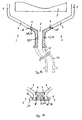
- Fig. 12 shows a horizontal section through the housing 1 and a plan view of the bottom wall 7.
- the bottom wall 7 is formed by the left and right housing part 2, 3.
- the parting line 4 between the left and right housing part 2, 3 is sealed by means of an elastic sealing element 34 as a sealing means 33 ( Fig. 12 to 16 ).
- the drain opening 8 is formed by the elastic sealing element 34 ( Fig. 12 . 13 ).
- a drain hose 35 can also be integrated as a component part of the sealing element 34, preferably in one piece, which in Fig. 11 is shown in dashed lines.
- the two housing parts 2, 3 are connected to the bottom wall 7 at two joints 4 exclusively with the elastic sealing element 34, ie there is no direct contact between the bottom wall 7 of the two housing parts 2, 3 on ( Fig. 13, 14th ).
- the bottom wall 7 of the respective housing parts 2, 3 is indirectly connected by the elastic sealing element 34.
- the elastic sealing element 34 also forms part of the bottom wall 7.
- latching shoulders 36 are formed, which are enclosed by a clamp 37 (FIG. Fig. 12 . 14 ).
- the clamp 37 exerts a compressive force on the elastic sealing element 34 so that the elastic sealing element 34 seals reliably and securely.
- a heat-shrinkable tube 16 or a shrink-wrap 17 may be attached to the latching hooks 36 (not shown).
- FIG. 15 From a certain distance of the parting line 4 of the drain opening 8, this is according to Fig. 15 educated.
- a tongue and groove joint 18 connects directly to the bottom housing part 2 belonging to the bottom wall 7 and formed by the right housing part 3 bottom wall 7.
- the elastic sealing element 34 is inserted into two recesses 38 formed by the bottom wall 7 above the tongue and groove joint 18. In this case, a compressive force is exerted on the elastic sealing element 34 because the sealing element 34 has an excess with respect to the recesses 38.
- the tongue and groove joint 18 on the bottom wall 7 according to Fig. 15 is necessary because the connection according to Fig. 14 has a lower mechanical stability.
- Fig. 16 a perspective view of the elastic sealing element 34 is shown.
- the existing on the mechanical sealing element 34 groove and spring connection 18 according to FIGS. 13 and 14 is in Fig. 14 not shown.
Landscapes
- Physics & Mathematics (AREA)
- Thermal Sciences (AREA)
- Engineering & Computer Science (AREA)
- Mechanical Engineering (AREA)
- Air-Conditioning For Vehicles (AREA)
Abstract
Description
- Die Erfindung betrifft eine Klimaanlage für ein Kraftfahrzeug, umfassend ein von einem linken und rechten Gehäuseteil wenigstens teilweise gebildetes Gehäuse zur Aufnahme eines Kältemittelverdampfers, wobei zwischen dem linken und rechten Gehäuseteil eine Trennfuge auftritt, einen im Gehäuse angeordneten Kältemittelverdampfer, eine von dem Gehäuse gebildete Bodenwandung zum Sammeln des am Kältemittelverdampfer sich bildenden Kondenswassers und wenigstens eine in der Bodenwandung angeordnete Ablauföffnung zum Abführen des am Kältemittelverdampfer gebildeten Kondenswassers. Die Erfindung betrifft ferner eine Klimaanlage für ein Kraftfahrzeug, umfassend ein von einem linken und rechten Gehäuseteil wenigstens teilweise gebildetes Gehäuse zur Aufnahme eines Kältemittelverdampfers, wobei zwischen dem linken und rechten Gehäuseteil wenigstens eine Trennfuge auftritt, ein Dichtmittel zum Abdichten der Trennfuge, einen im Gehäuse angeordneten Kältemittelverdampfer, eine Bodenwandung zum Sammeln des am Käftemittelverdampfer sich bildenden Kondenswassers und wenigstens eine in der Bodenwandung angeordnete Ablauföffnung zum Abführen des am Kältemittelverdampfer gebildeten Kondenswassers.
- Bestandteil von Klimaanlagen für Kraftfahrzeuge bilden HVAC-Gehäuse aus Kunststoff mit einem Kältemittelverdampfer zum Kühlen und einer Heizeinrichtung zum Erwärmen einer in den Innenraum des Kraftfahrzeuges zu leitenden Luft. Die Gehäuse können eine Trennung in ein oberes und ein unteres Gehäuseteil oder in ein linkes und ein rechtes Gehäuseteil vorsehen, so dass das Gehäuse aus zwei Bauteilen besteht. Ferner kann auch eine Trennung in ein linkes unteres, ein rechtes unteres und ein oberes Gehäuseteil ausgebildet sein. Zwischen den Gehäuseteilen bildet sich eine Trennfuge aus. Am Kältemittelverdampfer schlägt sich Kondenswasser nieder, welches auf der Bodenwandung des Gehäuses aufgefangen und durch eine Ablauföffnung aus dem Gehäuse geleitet wird. Gehäuse mit einer Trennung nur in ein oberes und unteres Gehäuseteil verfügen im Bereich der mit Kondenswasser beaufschlagten Bodenwandung nicht über eine Trennfuge, so dass an der Trennfuge keine Dichtigkeitsprobleme wegen des Kondenswassers auftreten können. In Gehäusen mit einem linken und rechten Gehäuseteil tritt an der von dem Gehäuse gebildeten Bodenwandung eine Trennfuge auf, welche abgedichtet werden muss.
- Gehäuse mit einer Trennung in ein rechtes und linkes Gehäuseteil haben den Vorteil, dass diese im Allgemeinen kleiner und kompakter sind. Zum Abdichten der mit Kondenswasser beaufschlagten Bodenwandung des Gehäuses kann ein Einsatzteil im Bereich der Bodenwandung eingesetzt werden. Ferner ist es möglich, die Trennfuge im Bereich der Bodenwandung mit einer elastischen Dichtung oder mittels eines Verschweißens abzudichten. Die Maßnahmen zum Abdichten der Trennfuge sind aufwendig und kostenintensiv. Trotzdem können Undichtigkeiten, z. B. bei einem Schrumpfen der elastischen Dichtung, auftreten.
- Aus der
EP 1 122 103 A2 und derUS 5 954 578 sind gattungsbildende Klimaanlagen bekannt. Das Gehäuse besteht aus einem linken und rechten Gehäuseteil. Die beiden Gehäuseteile sind mittels einer Nut- und Federverbindung miteinander verbunden. Im Bereich der mit Kondenswasser beaufschlagten Bodenwandung ist in der Nut- und Federverbindung eine elastische Dichtung angeordnet. Durch eine Ablauföffnung wird das Kondenswasser aus dem Gehäuse geleitet. Nachteiligerweise können an der Nut- und Federverbindung, z. B. bei Toleranzabweichungen in der Fertigung, Undichtigkeiten auftreten und die Dichtung und deren Montage ist aufwendig und teuer. - Die Aufgabe der vorliegenden Erfindung besteht deshalb darin, bei einer Klimaanlage mit einer Trennung in ein linkes und rechtes Gehäuse eine sichere und zuverlässige Abdichtung der Trennfuge in der mit Kondenswasser beaufschlagten Bodenwandung zu ermöglichen. Die Klimaanlage soll in der Herstellung einfach und preiswert sowie auch bei Abweichungen in der Fertigungstoleranz der Gehäuseteile eine problemlose Abdichtung gewährleistet sein.
- Diese Aufgabe wird gelöst mit einer Klimaanlage für ein Kraftfahrzeug, umfassend ein von einem linken und rechten Gehäuseteil wenigstens teilweise gebildetes Gehäuse zur Aufnahme eines Kältemittelverdampfers, wobei zwischen dem linken und rechten Gehäuseteil eine Trennfuge auftritt, einen im Gehäuse angeordneten Kältemittelverdampfer, eine von dem Gehäuse gebildete Bodenwandung zum Sammeln des am Kältemittelverdampfer sich bildenden Kondenswassers und wenigstens eine in der Bodenwandung angeordnete Ablauföffnung zum Abführen des am Kältemittelverdampfer gebildeten Kondenswassers, wobei an der Bodenwandung die Trennfuge ausschließlich oberhalb der Ablauföffnung angeordnet ist. Die Trennfuge wird damit nur mit Schwellwasser und nicht mit stehendem Wasser beaufschlagt. Stehendes Wasser kann beispielsweise an der Bodenwandung auftreten, wenn die Ablauföffnung teilweise verstopft ist oder, z. B. bei Erschütterungen, kurzfristig eine größere Menge an Kondenswasser vom Kältemittelverdampfer auf die Bodenwandung fällt. Ferner liegt ein Gefälle zwischen der Trennfuge und der Ablauföffnung vor, so dass das Kondenswasser an der Trennfuge nicht steht, sondern fließt. Die Auslegung des Ablaufs erfolgt typischerweise so, dass ungefähr ein halber Liter Wasser in ca. 15 Sekunden ablaufen kann.
- In einer weiteren Ausgestaltung ist die Trennfuge, vorzugsweise in vertikaler Richtung, um mehr als 0,5 cm, insbesondere um mehr als 1 cm, ausschließlich oberhalb der Ablauföffnung angeordnet.
- In einer ergänzenden Ausführungsform ist die Neigung der Bodenwandung in einer Richtung senkrecht zur Ebene der Trennfuge beiderseits der Trennfuge nach unten zur wenigstens einen Ablauföffnung gerichtet, insbesondere mit einer Neigung von mehr als 17°. Die Bodenwandung beiderseits der Trennfuge ist entweder einheitlich zu einer Ablauföffnung geneigt oder entgegengesetzt geneigt, d. h. als Dachprofil ausgebildet, zu je einer Ablauföffnung geneigt.
- Zweckmäßig ist die Trennfuge im Bereich einer maximalen Höhe der Bodenwandung angeordnet. Die Trennfuge ist somit in einem Bereich einer maximalen Höhe der Bodenwandung ausgebildet, so dass das Kondenswasser beiderseits der Trennfuge in entgegengesetzter Richtung abläuft.
- In einer weiteren Ausgestaltung ist die Trennfuge in einem nur in eine Richtung zur Ablauföffnung geneigten Bodenwandung, vorzugsweise mittig, zwischen einem Bereich einer minimalen Höhe der Bodenwandung, insbesondere mit der Ablauföffnung, und einem Bereich einer maximalen Höhe der Bodenwandung ausgebildet. Das auf der Bodenwandung auftreffende Kondenswasser läuft beiderseits der Trennfuge in die gleiche Richtung zu der Ablauföffnung ab.
- Vorzugsweise ist die Trennfuge von einer Dichtrippe und/oder einem Klemmprofil überdeckt. Damit kann das Kondenswasser nicht von oben unmittelbar auf der Trennfuge auftreffen, so dass ein kurzzeitiger Wasserdruck an der Trennfuge, verursacht durch einen direkt auf der Trennfuge auftreffenden Kondenswassertropfen, nicht auftreten kann.
- Insbesondere ist die Dichtrippe an einem Gehäuseteil fixiert.
- In einer weiteren Ausgestaltung ist die Dichtrippe einstückig mit dem einen Gehäusesteil ausgebildet. Die Dichtrippe kann damit beispielsweise einfach beim Spritzgießen des Gehäuseteils an der Bodenwandung hergestellt werden. Die Dichtrippe besteht damit aus demselben Material wie das Gehäuse.
- Alternativ besteht die Dichtrippe bevorzugt aus einem elastomeren Material und ist insbesondere mittel der Technik des Zwei-Komponenten Spritzgusses einstückig mit dem Gehäuse hergestellt.
- In einer zusätzlichen Ausgestaltung erstreckt sich die Dichtrippe von einem höher liegenden Abschnitt der Bodenwandung zu einem tiefer liegenden Abschnitt der Bodenwandung und die Dichtrippe ist einstückig mit dem höher liegenden Abschnitt der Bodenwandung ausgebildet. Das Kondenswasser läuft somit vom höher liegenden Abschnitt der Bodenwandung über die Dichtrippe zum tiefer liegenden Abschnitt der Bodenwandung.
- Insbesondere ist ein Ende der Dichtrippe als Tropfnase ausgebildet und die Tropfnase überdeckt die Trennfuge in einem Abstand. Die Tropfnase bewirkt, dass Kondenswassertropfen kontrolliert in einem Abstand von der Trennfuge auf die Bodenwandung fallen.
- Vorzugsweise ist ein zwischen Dichtrippe und Bodenwandung gebildeter Hohlraum von einer an einem anderen Gehäuseteil fixierten zusätzlichen Dichtrippe ausgefüllt. Die Trennfuge wird dadurch vergrößert, so dass dem Kondenswasser ein größerer Strömungswiderstand zum Durchfließen der Trennfuge entgegensteht.
- In einer weiteren Ausgestaltung ist die zusätzliche Dichtrippe einstückig mit dem anderen Gehäuseteil ausgebildet.
- In einer zusätzlichen Ausführungsform sind beide Dichtrippen von einem Schrumpfschlauch oder einer Schrumpffolie oder einem Klemmprofil umschlossen. Der Schrumpfschlauch oder die Schrumpffolie dichten damit die Trennfuge zusätzlich ab. Das Klemmprofil drückt beide Dichtrippen gegeneinander und/oder dichtet die Trennfuge zusätzlich ab.
- Insbesondere ist die Trennfuge von einer Nut- und Federverbindung gebildet. Die Nut- und Federverbindung ermöglicht eine formschlüssige Verbindung zwischen den beiden Gehäuseteilen.
- In einer weiteren Ausgestaltung ist an einer nicht mit Kondenswasser beaufschlagten Unterseite der Bodenwandung an der Trennfuge bei jedem der Gehäuseteile eine vorstehende Dichtlippe ausgebildet, welche von einem Schrumpfschlauch oder einer Schrumpffolie oder einem Klemmprofil umschlossen sind. Der Schrumpfschlauch oder die Schrumpffolie oder das Klemmprofil dichten damit die Trennfuge an der Unterseite zusätzlich ab. Das Klemmprofil drückt vorzugsweise beide vorstehende Dichtlippen aneinander.
- Zweckmäßig ist die Nut- und Federverbindung wenigstens teilweise in der Dichtlippe angeordnet.
- In einer weiteren Ausgestaltung wird von dem Klemmprofil und/oder einem Schrumpfschlauch oder einer Schrumpffolie eine Notablaufrinne eingeschlossen. Vorzugsweise ist Kondenswasser von der Notablaufrinne in einen Kondenswasserablauf leitbar. Beispielsweise ist die Notablaufrinne von einer länglichen Ausnehmung in einer Dichtlippe gebildet. Die Notablaufrinne ist bevorzugt an der Unterseite der Bodenwandung ausgebildet.
- Zweckmäßig drückt das elastische Klemmprofil das linke und rechte Gehäuseteil an der Trennfuge gegeneinander, beispielsweise indem das Klemmprofil die Dichtrippe und die Zusatzrippe oder beide Dichtlippen umschließt.
- In einer Variante ist zwischen dem linken und rechten Gehäuseteil wenigstens teilweise das elastische Klemmprofil angeordnet, so dass das Klemmprofil die Trennfuge abdichtet.
- Insbesondere ist die wenigstens eine Ablauföffnung ein einem Tiefpunkt der Bodenwandung ausgebildet.
- In einer weiteren Ausgestaltung ist im Gehäuse eine Heizeinrichtung und/oder ein Filter und/oder eine elektrische Nachheizung und/oder eine Prallwand und/oder wenigstens eine Luftklappe und/oder ein Gebläse angeordnet.
- Eine erfindungsgemäße Klimaanlage für ein Kraftfahrzeug umfasst ein von einem linken und rechten Gehäuseteil wenigstens teilweise gebildetes Gehäuse zur Aufnahme eines Kältemittelverdampfers, wobei zwischen dem linken und rechten Gehäuseteil wenigstens eine Trennfuge auftritt, ein Dichtmittel zum Abdichten der wenigstens einen Trennfuge, einen im Gehäuse angeordneten Kältemittelverdampfer, eine von dem Gehäuse gebildete Bodenwandung zum Sammeln des am Kältemittelverdampfer sich bildenden Kondenswassers und wenigstens eine in der Bodenwandung angeordnete Ablauföffnung zum Abführen des am Kältemittelverdampfer gebildeten Kondenswassers, wobei die vom linken und rechten Gehäuseteil gebildete Bodenwandung mittels dem Dichtmittel, insbesondere an der wenigstens einen Trennfuge, ausschließlich mittelbar miteinander verbunden ist oder keine unmittelbare Verbindung, vorzugsweise an der wenigstens einen Trennfuge, zwischen der vom linken und rechten Gehäuseteil gebildeten Bodenwandung besteht.
- Insbesondere bildet das Dichtmittel die Ablauföffnung.
- In einer weiteren Ausgestaltung bildet das Dichtmittel, vorzugsweise einteilig, einen Anschlussstutzen. Damit ist kein zusätzlicher Anschlussstutzen erforderlich und der Anschlussstutzen kann einfach elastisch ausgeführt werden.
- In einer zusätzlichen Ausgestaltung ist die wenigstens eine Trennfuge von einer Nut- und Federverbindung gebildet.
- Insbesondere ist das Dichtmittel ein elastisches Dichtelement.
- Im Nachfolgenden werden zwei Ausführungsbeispiele der Erfindung unter Bezugnahme auf die beigefügten Zeichnungen näher beschrieben. Es zeigt:
-
Fig. 1 einen Querschnitt eines Gehäuses für eine Kraftfahrzeugklimaanlage eines ersten Ausführungsbeispiels, -
Fig. 2 einen Querschnitt einer Bodenwandung des Gehäuses in einer ersten Ausführungsform des ersten Ausführungsbeispiels, -
Fig. 3 einen Querschnitt der Bodenwandung des Gehäuses in einer zweiten Ausführungsform des ersten Ausführungsbeispiels, -
Fig. 4 einen Querschnitt der Bodenwandung des Gehäuses in einer dritten Ausführungsform des ersten Ausführungsbeispiels, -
Fig. 5 einen Querschnitt einer Trennfuge in einer ersten Ausführungsform für die Bodenwandung gemäßFig. 2 , -
Fig. 6 einen Querschnitt der Trennfuge in einer zweiten Ausführungsform für die Bodenwandung gemäßFig. 3 oder 4 , -
Fig. 7 einen Querschnitt der Trennfuge in einer dritten Ausführungsform für die Bodenwandung gemäßFig. 3 oder 4 , -
Fig. 8 einen Querschnitt der Trennfuge in einer vierten Ausführungsform für die Bodenwandung gemäßFig. 3 oder 4 , -
Fig. 9 eine perspektivische Ansicht der Verbindung zwischen dem linken und rechten Gehäuseteil gemäßFig. 8 , -
Fig. 10 einen Querschnitt der Trennfuge in einer fünften Ausführungsform für die Bodenwandung gemäßFig. 3 oder 4 , -
Fig. 11 einen Querschnitt der Trennfuge in einer sechsten Ausführungsform für die Bodenwandung gemäßFig. 3 oder 4 , -
Fig. 12 einen horizontalen Schnitt durch das Gehäuse und eine Draufsicht auf die Bodenwandung des zweiten Ausführungsbeispiels, -
Fig. 13 einen Querschnitt gemäß Schnitt A-A inFig. 12 , -
Fig. 14 einen Querschnitt gemäß Schnitt B-B inFig. 12 , -
Fig. 15 einen Querschnitt gemäß Schnitt C-C inFig. 12 und -
Fig. 16 eine vereinfachte perspektivische Ansicht eines elastischen Dichtelements des zweiten Ausführungsbeispiels. -
Figur 1 zeigt einen Querschnitt eines Gehäuses 1 für eine Klimaanlage eines Kraftfahrzeuges (nicht dargestellt). Das Gehäuse 1 besteht aus einem linken Gehäuseteil 2 und einem rechten Gehäuseteil 3 (inFig. 2, 3 und 4 teilweise dargestellt). Zwischen dem linken und rechten Gehäuseteil 2, 3 bildet sich somit eine Trennfuge 4 aus (inFig. 1 nicht dargestellt). Die Ebene der Trennfuge 4 ist vertikal ausgerichtet. Die übrigen Bestandteile der Klimaanlage, z. B. ein Kältemittelkondensator und ein Verdichter, sind nicht dargestellt. - Das Gehäuse 1 nimmt ein Gebläse 23, einen Filter 20, einen Kältemittelverdampfer 5, eine vom Kühlwasser des Motors durchflossene Heizeinrichtung 6 und eine elektrische Nachheizung 22 auf. Die Luft für den Fahrgastraum wird vom Gebläse 23 durch den Filter 20 und den Kältemittelverdampfer 5 geleitet. Durch die Abkühlung des Luftstromes im Kältemittelverdampfer 5 schlägt sich die im Luftstrom enthaltene Feuchtigkeit am Kältemittelverdampfer 5 nieder und es bilden sich Kondenswassertropfen auf dem Kältemittelverdampfer 5. Die Kondenswassertropfen fallen ab einer bestimmten Größe aufgrund der Schwerkraft auf eine vom Gehäuse 1 gebildete Bodenwandung 7 und sammeln sich hier. Bei größeren Luftströmungsgeschwindigkeiten können auch Kondenswassertropfen vom Luftstrom in Richtung der Heizeinrichtung 6 mitgerissen werden. Eine Prallwand 21 dient dazu, die von dem Luftstrom mitgerissenen Kondenswassertropfen zurückzuhalten und in Richtung der Bodenwandung 7 zu leiten. Nicht dargestellte Luftklappen steuern den Anteil des Luftstromes, der nach dem Durchströmen des Kältemittelverdampfers 5 durch die Heizeinrichtung 6 und/oder die elektrische Nachheizung 22 geleitet wird. Die erwärmte und/oder gekühlte Luft verlässt durch eine Austrittsöffnung 24 das Gehäuse 1. Die wasserdicht auszubildende Bodenwandung 7 ist in
Fig. 1 mit einem strichpunktierten Kasten eingerahmt. - In den
Fig. 2 bis 4 ist ein Querschnitt der Bodenwandung 7 in drei Ausführungsformen dargestellt. - In
Fig. 2 ist die Bodenwandung 7 unterhalb des Kältemittelverdampfers 5 einheitlich von links nach rechts geneigt. Zwischen einem höher liegenden Abschnitt 12 der Bodenwandung 7 und einem tiefer liegenden Abschnitt 13 der Bodenwandung 7 ist mittig zwischen der minimalen Höhe 9 und der maximalen Höhe 10 der Bodenwandung 7 die Trennfuge 4 angeordnet. Das sich auf der Bodenwandung 7 sammelnde Kondenswasser fließt entsprechend dem Gefälle der Bodenwandung 7 zur vertikalen Ablauföffnung 8 und strömt durch die Ablauföffnung 8 aus dem Gehäuse 1. Die Ablauföffnung 8 kann auch horizontal ausgeführt sein (nicht dargestellt). Die Trennfuge 4 zwischen dem linken und rechten Gehäuseteil 2, 3 wird somit nicht mit stehendem Kondenswasser, sondern nur mit Schwellwasser beaufschlagt, weil das Kondenswasser an der Trennfuge 4 lediglich nach unten abfließt. Gesonderte Dichtmittel, z. B. eine elastische Dichtung, sind deshalb zum Abdichten der Trennfuge 4 nicht erforderlich. - In
Fig. 3 ist die Bodenwandung 7 als ein Dachprofil ausgebildet. Der Bereich mit einer maximalen Höhe 10 ist mittig zwischen zwei Bereichen mit einer minimalen Höhe 9 der Bodenwandung 7 ausgebildet. Das Kondenswasser strömt durch zwei horizontale Ablauföffinungen 8 aus dem Gehäuse 1, die am Bereich mit der minimalen Höhe 9 der Bodenwandung 7 ausgeführt sind. Die Ablauföffnungen 8 können auch vertikal ausgebildet sein (nicht dargestellt). Die Trennfuge 4 befindet sich an dem Bereich mit der maximalen Höhe 10 der Bodenwandung 7, so dass an der Trennfuge 4 kein stehendes Wasser, sondern nur Schwellwasser auftritt. - In einer dritten Ausführungsform ist in
Fig. 4 die Bodenwandung 7 in vier Abschnitte 25, 26, 27, 28 unterteilt. Die beiden inneren Abschnitte 25, 26 sind als Dachprofil ausgebildet an denen sich jeweils ein weiterer Abschnitt 27, 28 der Bodenwandung 7 mit einer einheitlichen Neigung anschließt. Die Trennfuge 4 befindet sich an der maximalen Höhe 10 der Bodenwandung 7 zwischen den beiden inneren Abschnitten 25, 26 der Bodenwandung 7. Die beiden vertikalen Ablauföffnungen 8 sind jeweils zwischen dem äußeren Abschnitt 27, 28 und einem daran anschließenden inneren Abschnitt 25, 26 angeordnet. Die Ablauföffnungen 8 können auch horizontal ausgebildet sein (nicht dargestellt). Damit tritt an der Trennfuge 4 nur Schwellwasser und kein stehendes Wasser auf. - In den in den
Fig. 2 bis 4 dargestellten Ausführungsformen verfügt die Bodenwandung 7 senkrecht zur Zeicheneben über ein Gefälle, damit das Kondenswasser zu den senkrecht zur Zeichenebene nur lokal angeordneten Ablauföffnungen 8 fließen kann. - Die
Fig. 5 bis 11 zeigen im Detail die Ausbildung der Trennfuge 4 als Nut- und Federverbindung 18. -
Fig. 5 zeigt die Trennfuge 4 für die Bodenwandung 7 gemäßFig. 2 . Oberhalb der Nut- und Federverbindung 18 ist eine Dichtrippe 11 vorhanden, welche einstückig an dem höher liegenden Abschnitt 12 der Bodenwandung 7 hergestellt ist und die Trennfuge 4 überdeckt. Die Dichtrippe 11 liegt auf dem tiefer liegenden Abschnitt 13 der Bodenwandung 7 auf. Das Kondenswasser fließt an der Oberseite 29 der Bodenwandung 7 vom höher liegenden Abschnitt 12 der Bodenwandung 7 über die Dichtrippe 11 zum tiefer liegenden Abschnitt 13 der Bodenwandung 7. Damit kann Schwallwasser, wenn überhaupt, nur temporär in die Trennfuge 4 eindringen. An der Unterseite 30 der Bodenwandung 7 ist an jedem Gehäuseteil 2, 3 eine Dichtlippe 19 vorhanden. Die Dichtlippen 19 werden teilweise von der Nut- und Federverbindung 18 gebildet und sind von einem optionalen Schrumpfschlauch 16 oder einer optionalen Schrumpffolie 17 umschlossen. Der Schrumpfschlauch 16 oder die Schrumpffolie 17 dienen zum ergänzenden Abdichten der Trennfuge 4. - Zusätzlich können an den beiden Dichtlippen 19 mechanische Fixiermittel, z. B. Klemmen (nicht dargestellt), positioniert sein, welche die beiden Gehäuseteile 2, 3 zusammendrücken und darüber hinaus den Schrumpfschlauch 16 oder die Schrumpffolie 17 befestigen. Der Neigungswinkel α der Bodenwandung 7 ist größer als 17°. Anstelle des Schrumpfschlauches 16 oder der Schrumpffolie 17 kann ein, vorzugsweise elastisches, Klemmprofil 40 über die beiden Dichtlippen 19 geschoben werden. Das im Querschnitt ungefähr C-förmige Klemmprofil 40 ist vollständig und nicht nur punktuell entlang der Dichtlippen 19 angeordnet, so dass sich in einer Notablaufrinne 39 Kondenswasser sammeln kann, welches durch die Nut- und Federverbindung 18 durchgedrungen ist. Dieses in der Notablaufrinne 39 gesammelte Wasser wird zu einem Kondenswasserablauf (nicht dargestellt) geleitet, so dass das Kondenswasser keinen Schaden anrichten kann. Das Klemmprofil 40 drückt die beiden Gehäuseteile 2, 3 zusammen und dichtet ergänzend ab. Die Geometrie des Klemmprofiles 40 ist dahingehend bemessen, dass aufgrund einer elastischen Verformung beide Gehäuseteile 2, 3 zusammengedrückt werden.
- Die
Fig. 6 bis 11 zeigen die Trennfuge 4 für die Bodenwandung 7 gemäßFig. 3 und 4 . - In einer zweiten Ausführungsform der Trennfuge 4 ist die zum Gehäuseteil 3 gehörenden Bodenwandung 7 mit einer Dichtrippe 11 versehen (
Fig. 6 ). Ein Ende der Dichtrippe 11 verfügt über eine Tropfnase 15, so dass von oben aus dem Kältemittelverdampfer 4 auf die Trennfuge 4 herabfallende Kondenswassertropfen nicht unmittelbar auf der Trennfuge 4 auftreffen können und Kondenswassertropfen kontrolliert in einem Abstand von der Trennfuge 4 auf der Oberseite 29 der zum linken Gehäuseteil 2 gehörenden Bodenwandung 7 fallen. Zwischen der Dichtrippe 11 mit Tropfnase 15 und der zum linken Gehäuseteil 2 gehörenden Bodenwandung 7 bildet sich somit ein Hohlraum 14. Der Neigungswinkel β der zum linken Gehäuseteil 2 gehörenden Bodenwandung 7 an der Trennfuge 4 unterhalb der Tropfnase 15 soll mehr als 0° betragen, d. h. die Bodenwandung 7 unterhalb der Tropfnase 15 soll eine abfallende Neigung weg von der Trennfuge 4 aufweisen, damit das Kondenswasser auf der Bodenwandung 7 unterhalb der Tropfnase 15 von der Trennfuge 4 abfließt. Die Neigung der Bodenwandung 7 auf beiden Seiten der Trennfuge 4 soll größer als 17° sein, damit das Kondenswasser auch bei einer Schrägstellung des Kraftfahrzeuges, z. B. bei Steigungsstrecken, abfließen kann. Der Neigungswinkel β ist inFig. 6 gleich dem Neigungswinkel α. - Die dritte Ausführungsform (
Fig. 7 ) der Trennfuge 4 unterscheidet sich von der zweiten Ausführungsform (Fig. 6 ) durch eine zusätzliche Dichtrippe 31, welche den Hohlraum 14 zwischen der Dichtrippe 11 und der zum linken Gehäuseteil 2 gehörenden Bodenwandung 7 ausfüllt. Dadurch kann optional die Dichtrippe 11 und die zusätzliche Dichtrippe 31 von einem Schrumpfschlauch 16 oder einer Schrumpffolie 17 zum Abdichten der Trennfuge umschlossen werden. Der Schrumpfschlauch 16 oder die Schrumpffolie 17 ist inFig. 7 strichpunktiert im ungeschrumpften Zustand dargestellt. - Die vierte Ausführungsform (
Fig. 8 ,9 ) der Trennfuge 4 unterscheidet sich von der ersten Ausführungsform (Fig. 5 ) dadurch, dass die zum rechten Gehäuseteil 3 gehörende Bodenwandung 7 nicht zur Trennfuge 4, sondern von der Trennfuge 4 weg geneigt ist, d. h. ein Dachprofil vorliegt. Das auf der Dichtrippe 11 auftreffende Kondenswasser fließt auf der Bodenwandung 7, welche dem linken Gehäuseteil 2 zuzuordnen ist, als auch auf der Bodenwandung 7, die vom rechten Gehäuseteil 3 gebildet wird, in entgegengesetzter Richtung. - In den Ausführungsformen zwei bis vier der Trennfuge 4 gemäß
Fig. 6 bis 9 können, analog zur ersten Ausführungsform, optional die beiden Dichtlippen 19 an der Unterseite 30 der Bodenwandung 7 von dem Schrumpfschlauch 16 oder der Schrumpffolie 17 oder dem Klemmprofil 40 umschlossen sein und vorzugsweise eine Notablaufrinne 39 ausgebildet sein. Sofern in einer oder beiden Dichtlippen 19 keine Ausnehmung als Notablaufrinne 39 ausgebildet ist, kann die Notablaufrinne 39 auch von einem länglichen Hohlraum zwischen den Dichtlippen 19 und dem Klemmprofil 40 gebildet werden, indem das Klemmprofil 40 in wenigstens einem Teilbereich einen Abstand zu den beiden Dichtlippen 19 aufweist (nicht dargestellt). -
Fig. 10 zeigt einen Querschnitt der Trennfuge 4 in einer fünften Ausführungsform für die Bodenwandung 7. Die Trennfuge 4 wird untenseitig von der Nut- und Federverbindung 18 mit zwei Dichtlippen 19 gebildet. Oberseitig sind die Dichtrippe 11 und die zusätzliche Dichtrippe 31 parallel zueinander mit einem Abstand zueinander ausgebildet, so dass sich ein Spalt 41 bildet. In dem Spalt 41 und außenseitig an der Dichtrippe 11 und der Zusatzdichtrippe 31 ist ein elastisches Klemmprofil 40 aus Kunststoff angeordnet, das die Dichtrippe 11 und die zusätzliche Dichtrippe 31 umgreifen. Das Klemmprofil 40 ersetzt z. B. die Klammer an den beiden Dichtlippen 19 und drückt die beiden Gehäuseteile 2, 3 an der Trennfuge 4 zusammen, da das Klemmprofil 40 die Dichtrippe 11 und die zusätzliche Dichtrippe 31 umgreifen und dabei eine Druckkraft aufgrund einer elastischen Verformung des Klemmprofiles 40 auf die Dichtrippe 11 und die zusätzliche Dichtrippe 31 aufbringen. Dabei ist der Teil des Klemmprofiles 40, der in dem Spalt 41 angeordnet ist, geringfügig größer als der Spalt 41, sofern das linke und rechte Gehäuseteil 2, 3 zusammengedrückt werden und kein Klemmprofil 40 vorhanden ist. Dadurch wird bei der Anordnung gemäßFig. 10 der in dem Spalt 41 angeordnete Teil des Klemmprofiles 40 von der Dichtrippe 11 und der zusätzlichen Dichtrippe 31 unter Druckkraft eingeklemmt und aufgrund der elastischen Eigenschaften des Klemmprofiles 40 verformt. Damit dichtet das Klemmprofil 40 die Trennfuge 4 im Bereich des Spaltes 41 ab. Außerdem hält der außenseitig an der Dichtrippe 11 und der zusätzlichen Dichtrippe 31 angeordnete Teil des Klemmprofiles 40 von der Trennfuge 4 Kondenswasser fern. In der fünften Ausführungsform gemäßFig. 10 kann auf die Nut- und Federverbindung 18 auch verzichtet werden (nicht dargestellt). - Eine nicht dargestellte Ausführungsform unterscheidet sich von der fünften Ausführungsform gemäß
Fig. 10 dadurch, dass zwischen der Dichtrippe 11 und der zusätzlichen Dichtrippe 31 das Klemmprofl 40 nicht angeordnet ist und die Dichtrippe 11 und die zusätzliche Dichtrippe 31 ohne Spalt 41 unmittelbar aufeinander liegen an der vertikalen Trennfuge 4. Das Klemmprofil 40 ist im Querschnitt C-förmig und drückt die Dichtrippe 11 gegen die zusätzliche Dichtrippe 31. - In
Fig. 11 ist in einer sechsten Ausführungsform eine Ergänzung der zweiten Ausführungsform gemäßFig. 6 dargestellt. Auf die Dichtrippe 11 ist das im Querschnitt C-förmige Klemmprofil 40 aufgestülpt, so dass Kondenswasser von der Trennfuge 4 zwischen dem linken und rechten Gehäuseteil 2, 3 ferngehalten wird. - Die Einzelheiten der verschiedenen Ausführungsformen und/oder Ausführungsbeispiele können miteinander kombiniert werden, sofern nichts Gegenteiliges erwähnt wird.
- In den
Fig. 12 bis 16 ist das zweite Ausführungsbeispiel dargestellt.Fig. 12 zeigt einen horizontalen Schnitt durch das Gehäuse 1 und eine Draufsicht auf die Bodenwandung 7. Die Bodenwandung 7 wird von dem linken und rechten Gehäuseteil 2, 3 gebildet. Die Trennfuge 4 zwischen dem linken und rechten Gehäuseteil 2, 3 ist mittels eines elastischen Dichtelements 34 als Dichtmittel 33 abgedichtet (Fig. 12 bis 16 ). Die Ablauföffnung 8 wird von dem elastischen Dichtelement 34 gebildet (Fig. 12 ,13 ). Optional kann an der von dem elastischen Dichtelement 34 gebildeten Ablauföffnung 8 auch ein Ablaufschlauch 35 als, vorzugsweise einteiliger, Bestandteil des Dichtelements 34 integriert sein, welcher inFig. 11 strichliert dargestellt ist. Im Bereich der Ablauföffnung 8 und bis zu einem bestimmten Abstand von der Ablauföffnung 8 sind die beiden Gehäuseteile 2, 3 an der Bodenwandung 7 an beiden Trennfugen 4 ausschließlich mit dem elastischen Dichtelement 34 verbunden, d. h. es tritt kein unmittelbarer Kontakt zwischen der Bodenwandung 7 der beiden Gehäuseteile 2, 3 auf (Fig. 13, 14 ). Die Bodenwandung 7 der jeweiligen Gehäuseteile 2, 3 ist mittelbar durch das elastische Dichtelement 34 verbunden. Es treten zwei Trennfugen 4 auf, die jeweils von einer Nut- und Federverbindungen 18 gebildet sind. Das elastische Dichtelement 34 bildet auch einen Teil der Bodenwandung 7. An der Bodenwandung 7 sind im Bereich der Trennfuge 4 Rasthacken 36 ausgebildet, welche von einer Klemme 37 umschlossen sind (Fig. 12 ,14 ). Die Klemme 37 übt auf das elastische Dichtelement 34 eine Druckkraft auf, so dass das elastische Dichtelement 34 zuverlässig und sicher abdichtet. Ergänzend kann an den Rasthacken 36 auch ein Schrumpfschlauch 16 oder eine Schrumpffolie 17 angebracht sein (nicht dargestellt). - Ab einem bestimmten Abstand der Trennfuge 4 von der Ablauföffnung 8 ist diese gemäß
Fig. 15 ausgebildet. Eine Nut- und Federverbindung 18 verbindet unmittelbar die zum linken Gehäuseteil 2 gehörenden Bodenwandung 7 und die vom rechten Gehäuseteil 3 gebildete Bodenwandung 7. Das elastische Dichtelement 34 ist in zwei von der Bodenwandung 7 gebildeten Aussparungen 38 oberhalb der Nut- und Federverbindung 18 eingefügt. Dabei wird auf das elastische Dichtelement 34 eine Druckkraft ausgeübt, weil das Dichtelement 34 bezüglich der Aussparungen 38 ein Übermaß aufweist. Die Nut- und Federverbindung 18 an der Bodenwandung 7 gemäßFig. 15 ist notwendig, weil die Verbindung gemäßFig. 14 über eine geringere mechanische Stabilität verfügt. InFig. 16 ist eine perspektivische Ansicht des elastischen Dichtelements 34 dargestellt. Die an dem mechanischen Dichtelement 34 vorhandene Nut- und Federverbindung 18 gemäßFig. 13 und 14 ist inFig. 14 nicht dargestellt. -
- 1
- Gehäuse
- 2
- Linkes Gehäuseteil
- 3
- Rechtes Gehäuseteil
- 4
- Trennfuge
- 5
- Kältemittelverdampfer
- 6
- Heizeinrichtung
- 7
- Bodenwandung
- 8
- Ablauföffnung
- 9
- Minimale Höhe der Bodenwandung
- 10
- Maximale Höhe der Bodenwandung
- 11
- Dichtrippe
- 12
- Höher liegender Abschnitt der Bodenwandung
- 13
- Tiefer liegender Abschnitt der Bodenwandung
- 14
- Hohlraum
- 15
- Tropfnase
- 16
- Schrumpfschlauch
- 17
- Schrumpffolie
- 18
- Nut- und Federverbindung
- 19
- Dichtlippe
- 20
- Filter
- 21
- Prallwand
- 22
- Elektrische Nachheizung
- 23
- Gebläse
- 24
- Austrittsöffnung
- 25
- Innerer Abschnitt der Bodenwandung
- 26
- Innerer Abschnitt der Bodenwandung
- 27
- Äußerer Abschnitt der Bodenwandung
- 28
- Äußerer Abschnitt der Bodenwandung
- 29
- Oberseite der Bodenwandung
- 30
- Unterseite der Bodenwandung
- 31
- Zusätzliche Dichtrippe
- 32
- Anschlussstutzen
- 33
- Dichtmittel
- 34
- Dichtelement
- 35
- Ablaufschlauch
- 36
- Rasthacken
- 37
- Klemme
- 38
- Aussparung
- 39
- Notablaufrinne
- 40
- Klemmprofil
- 41
- Spalt
Claims (15)
- Klimaanlage für ein Kraftfahrzeug, umfassend- ein von einem linken und rechten Gehäuseteil (2, 3) wenigstens teilweise gebildetes Gehäuse (1) zur Aufnahme eines Kältemittelverdampfers (5), wobei zwischen dem linken und rechten Gehäuseteil (2, 3) wenigstens eine Trennfuge (4) auftritt,- einen im Gehäuse (1) angeordneten Kältemittelverdampfer (5),- eine von dem Gehäuse gebildete Bodenwandung (7) zum Sammeln des am Kältemittelverdampfer (5) sich bildenden Kondenswassers und- wenigstens eine in der Bodenwandung (7) angeordnete Ablauföffnung (8) zum Abführen des am Kältemittelverdampfer (5) gebildeten Kondenswassers,dadurch gekennzeichnet, dass
an der Bodenwandung (7) die Trennfuge (4) ausschließlich oberhalb der Ablauföffnung (8) angeordnet ist. - Klimaanlage nach Anspruch 1,
dadurch gekennzeichnet, dass
die Trennfuge (4), vorzugsweise in vertikaler Richtung, um mehr als 0,5 cm, insbesondere um mehr als 1 cm, ausschließlich oberhalb der Ablauföffnung (8) angeordnet ist. - Klimaanlage nach einem oder mehreren der vorhergehenden Ansprüche,
dadurch gekennzeichnet, dass
die Neigung der Bodenwandung (7) in einer Richtung senkrecht zur Ebene der Trennfuge (4) beiderseits der Trennfuge (4) nach unten zur wenigstens einen Ablauföffnung (8) gerichtet ist, insbesondere mit einer Neigung von mehr als 17°. - Klimaanlage nach einem oder mehreren der vorhergehenden Ansprüche,
dadurch gekennzeichnet, dass
die Trennfuge (4) im Bereich einer maximalen Höhe der Bodenwandung (7) angeordnet ist. - Klimaanlage nach einem oder mehreren der Ansprüche 1 bis 3,
dadurch gekennzeichnet, dass
die Trennfuge (4) in einem nur in eine Richtung zur wenigstens einen Ablauföffnung (8) geneigten Bodenwandung (7), vorzugsweise mittig, zwischen einem Bereich einer minimalen Höhe (9) der Bodenwandung (7) und einem Bereich einer maximalen Höhe (10) der Bodenwandung (7) ausgebildet ist. - Klimaanlage nach einem oder mehreren der vorhergehenden Ansprüche,
dadurch gekennzeichnet, dass
die Trennfuge (4) von einer Dichtrippe (11) und/oder einem Klemmprofil (40) überdeckt ist. - Klimaanlage nach Anspruch 6,
dadurch gekennzeichnet, dass
die Dichtrippe (11) sich von einem höher liegenden Abschnitt (12) der Bodenwandung (7) zu einem tiefer liegenden Abschnitt (13) der Bodenwandung (7) erstreckt und die Dichtrippe (11) einstückig mit dem höher liegenden Abschnitt (12) der Bodenwandung (7) ausgebildet ist. - Klimaanlage nach einem oder mehreren der Ansprüche 6 bis 7,
dadurch gekennzeichnet, dass
ein Ende der Dichtrippe (11) als Tropfnase (15) ausgebildet ist und die Tropfnase (15) die Trennfuge (4) in einem Abstand überdeckt. - Klimaanlage nach einem oder mehreren der Ansprüche 6 bis 8,
dadurch gekennzeichnet, dass
ein zwischen Dichtrippe (11) und Bodenwandung (7) gebildeter Hohlraum (14) von einer an einem Gehäuseteil (2, 3) fixierten zusätzlichen
Dichtrippe (31) ausgefüllt ist. - Klimaanlage nach Anspruch 9,
dadurch gekennzeichnet, dass
beide Dichtrippen (11, 31) von einem Schrumpfschlauch (16) oder einer Schrumpffolie (17) oder einem Klemmprofil (40) umschlossen sind. - Klimaanlage nach einem oder mehreren der vorhergehenden Ansprüche,
dadurch gekennzeichnet, dass
an der nicht mit Kondenswasser beaufschlagten Unterseite (30) der Bodenwandung (7) an der Trennfuge (4) bei jedem der Gehäuseteile (2, 3) eine vorstehende Dichtlippe (19) ausgebildet ist, welche von einem Schrumpfschlauch (16) oder einer Schrumpffolie (17) oder einem Klemmprofil (40) umschlossen sind. - Klimaanlage für ein Kraftfahrzeug, umfassend- ein von einem linken und rechten Gehäuseteil (2, 3) wenigstens teilweise gebildetes Gehäuse (1) zur Aufnahme eines Kältemittelverdampfers (5), wobei zwischen dem linken und rechten Gehäuseteil (2, 3) wenigstens eine Trennfuge (4) auftritt,- ein Dichtmittel (33) zum Abdichten der wenigstens einen Trennfuge (4),- einen im Gehäuse (1) angeordneten Kältemittelverdampfer (5),- eine von dem Gehäuse (1) gebildete Bodenwandung (7) zum Sammeln des am Kältemittelverdampfer (5) sich bildenden Kondenswassers und- wenigstens eine in der Bodenwandung (7) angeordnete Ablauföffnung (8) zum Abführen des am Kältemittelverdampfer (5) gebildeten Kondenswassers,dadurch gekennzeichnet, dass
die vom linken und rechten Gehäuseteil (2, 3) gebildete Bodenwandung (7) mittels dem Dichtmittel (33) an der wenigstens einen Trennfuge (4) ausschließlich mittelbar miteinander verbunden ist. - Klimaanlage nach Anspruch 12,
dadurch gekennzeichnet, dass
das Dichtmittel (33) die Ablauföffnung (8) bildet. - Klimaanlage nach einem oder mehreren der vorhergehenden Ansprüche,
dadurch gekennzeichnet, dass
die wenigstens eine Trennfuge (4) von einer Nut- und Federverbindung (18) gebildet ist. - Klimaanlage nach einem oder mehreren der vorhergehenden Ansprüche,
dadurch gekennzeichnet, dass
im Gehäuse (1) eine Heizeinrichtung (6) und/oder ein Filter (20) und/oder eine elektrische Nachheizung (22) und/oder eine Prallwand (21) und/oder wenigstens eine Luftklappe und/oder ein Gebläse (23) angeordnet ist.
Applications Claiming Priority (1)
| Application Number | Priority Date | Filing Date | Title |
|---|---|---|---|
| DE102007057168 | 2007-11-26 |
Publications (3)
| Publication Number | Publication Date |
|---|---|
| EP2062761A2 true EP2062761A2 (de) | 2009-05-27 |
| EP2062761A3 EP2062761A3 (de) | 2009-07-15 |
| EP2062761B1 EP2062761B1 (de) | 2011-02-16 |
Family
ID=40157717
Family Applications (1)
| Application Number | Title | Priority Date | Filing Date |
|---|---|---|---|
| EP08020504A Not-in-force EP2062761B1 (de) | 2007-11-26 | 2008-11-26 | Klimaanlage für ein Kraftfahrzeug |
Country Status (2)
| Country | Link |
|---|---|
| EP (1) | EP2062761B1 (de) |
| DE (2) | DE102008059085A1 (de) |
Cited By (6)
| Publication number | Priority date | Publication date | Assignee | Title |
|---|---|---|---|---|
| EP2284027A3 (de) * | 2009-08-14 | 2011-08-03 | Behr GmbH & Co. KG | Kraftfahrzeugklimaanlage |
| EP2514617A3 (de) * | 2011-04-20 | 2013-01-02 | Behr GmbH & Co. KG | Kraftfahrzeugklimaanlage |
| EP2378218A3 (de) * | 2010-04-15 | 2015-01-07 | Behr GmbH & Co. KG | Klimaanlage |
| FR3095160A1 (fr) * | 2019-04-17 | 2020-10-23 | Valeo Systemes Thermiques | Boîtier de protection étanche pour le domaine automobile |
| US20220049907A1 (en) * | 2018-12-19 | 2022-02-17 | Valeo Systemes Thermiques | Sealing device for a motor vehicle heat exchanger |
| CN116985854A (zh) * | 2023-07-31 | 2023-11-03 | 中铁城建集团有限公司 | 一种地铁通风空调排水机构 |
Families Citing this family (4)
| Publication number | Priority date | Publication date | Assignee | Title |
|---|---|---|---|---|
| SI2168796T1 (sl) | 2008-09-26 | 2013-05-31 | Valeo Klimasysteme Gmbh | Klimatska naprava za vozilo |
| DE102009057869A1 (de) * | 2009-12-11 | 2011-06-16 | Behr Gmbh & Co. Kg | Gehäuse für eine Kraftfahrzeugklimaanlage und Kraftfahrzeugklimaanlage |
| DE102016202444A1 (de) | 2016-02-17 | 2017-08-17 | Mahle International Gmbh | Klimaanlage eines Kraftfahrzeugs sowie Kraftfahrzeug |
| DE102017217628A1 (de) * | 2017-10-04 | 2019-04-04 | BSH Hausgeräte GmbH | Haushaltskältegerät mit einem endseitig flexiblen Ablaufrohr |
Citations (2)
| Publication number | Priority date | Publication date | Assignee | Title |
|---|---|---|---|---|
| US5954578A (en) | 1996-08-05 | 1999-09-21 | Denso Corporation | Air conditioner for a vehicle |
| EP1122103A2 (de) | 2000-02-03 | 2001-08-08 | Calsonic Kansei Corporation | Fahrzeugklimaanlage |
Family Cites Families (3)
| Publication number | Priority date | Publication date | Assignee | Title |
|---|---|---|---|---|
| DE9420291U1 (de) * | 1994-12-19 | 1995-10-19 | Siemens AG, 80333 München | Gehäuse aus zumindest zwei mittels einer Nut-Feder-Verbindung zusammensetzbaren Gehäuseteilen |
| FR2761013B1 (fr) * | 1997-03-18 | 1999-06-18 | Valeo Climatisation | Boitier d'appareil de chauffage-climatisation pour vehicule automobile |
| FR2769694B1 (fr) * | 1997-10-14 | 2000-01-28 | Valeo Climatisation | Boitier de dispositif de chauffage-climatisation pour vehicule automobile, comportant des moyens incorpores de recueil des condensats de l'evaporateur du climatiseur |
-
2008
- 2008-11-26 EP EP08020504A patent/EP2062761B1/de not_active Not-in-force
- 2008-11-26 DE DE102008059085A patent/DE102008059085A1/de not_active Withdrawn
- 2008-11-26 DE DE502008002602T patent/DE502008002602D1/de active Active
Patent Citations (2)
| Publication number | Priority date | Publication date | Assignee | Title |
|---|---|---|---|---|
| US5954578A (en) | 1996-08-05 | 1999-09-21 | Denso Corporation | Air conditioner for a vehicle |
| EP1122103A2 (de) | 2000-02-03 | 2001-08-08 | Calsonic Kansei Corporation | Fahrzeugklimaanlage |
Cited By (8)
| Publication number | Priority date | Publication date | Assignee | Title |
|---|---|---|---|---|
| EP2284027A3 (de) * | 2009-08-14 | 2011-08-03 | Behr GmbH & Co. KG | Kraftfahrzeugklimaanlage |
| EP2378218A3 (de) * | 2010-04-15 | 2015-01-07 | Behr GmbH & Co. KG | Klimaanlage |
| EP2514617A3 (de) * | 2011-04-20 | 2013-01-02 | Behr GmbH & Co. KG | Kraftfahrzeugklimaanlage |
| US20220049907A1 (en) * | 2018-12-19 | 2022-02-17 | Valeo Systemes Thermiques | Sealing device for a motor vehicle heat exchanger |
| US11859926B2 (en) * | 2018-12-19 | 2024-01-02 | Valeo Systemes Thermiques | Sealing device for a motor vehicle heat exchanger |
| FR3095160A1 (fr) * | 2019-04-17 | 2020-10-23 | Valeo Systemes Thermiques | Boîtier de protection étanche pour le domaine automobile |
| CN116985854A (zh) * | 2023-07-31 | 2023-11-03 | 中铁城建集团有限公司 | 一种地铁通风空调排水机构 |
| CN116985854B (zh) * | 2023-07-31 | 2024-04-16 | 中铁城建集团有限公司 | 一种地铁通风空调排水机构 |
Also Published As
| Publication number | Publication date |
|---|---|
| DE102008059085A1 (de) | 2009-07-09 |
| DE502008002602D1 (de) | 2011-03-31 |
| EP2062761A3 (de) | 2009-07-15 |
| EP2062761B1 (de) | 2011-02-16 |
Similar Documents
| Publication | Publication Date | Title |
|---|---|---|
| EP2062761B1 (de) | Klimaanlage für ein Kraftfahrzeug | |
| EP1437560B1 (de) | Kondensator mit Sammelbehälter und Schutzkappe | |
| DE102010062406B4 (de) | Klimagerät für ein Fahrzeug | |
| EP3283353B1 (de) | Windlaufabdeckungsanordnung für ein kraftfahrzeug | |
| EP2514617B1 (de) | Kraftfahrzeugklimaanlage | |
| DE102014109811B4 (de) | Luftleitvorrichtung zur Abluftführung | |
| DE102014112535B4 (de) | Kraftfahrzeugklimaanlage mit lösbar verbundenem Filterdeckel | |
| DE102007013690A1 (de) | Gehäuseteil für eine Heizungs- und/oder Klimaanlage | |
| EP1504803A1 (de) | Luft-Filter, insbesondere Kfz-Innenraumfilter | |
| DE4410120C2 (de) | Klimaanlage für ein Kraftfahrzeug | |
| EP4137339A1 (de) | Wasserablaufanordnung für ein fahrzeug | |
| DE102008007915A1 (de) | Deckel-Gehäuse-Anordnung, insbesondere für einen Filter eines Fahrzeug-Belüftungssystems | |
| DE102016203871A1 (de) | Klimaanlage | |
| DE10216868A1 (de) | Kunststoffölabweiser | |
| DE102015100093B4 (de) | Dichtungselement für ein Gehäuse eines Klimatisierungssystems eines Kraftfahrzeugs | |
| DE102017221771A1 (de) | Heizungs- oder Klimaanlage | |
| DE102014018299B4 (de) | Arbeitsmaschine mit Kabine und Verfahren zur Einstellung eines Ventils einer Arbeitsmaschine | |
| DE102016209628A1 (de) | Heizungs-, Belüftungs- oder Klimaanlage | |
| DE102008045595B4 (de) | Kraftfahrzeug-Luftfiltersystem und zugehöriges Montageverfahren | |
| EP1669224B1 (de) | Klimaanlage mit einem Verdampfer mit Kondenswasserablauf | |
| DE19753562A1 (de) | Vorrichtung zur Montage und Halterung eines Verdampfers in einem Gehäuse einer Heizungs- und Klimaanlage | |
| DE102021112524A1 (de) | Verdampfereinheit | |
| WO2023285361A1 (de) | Heizungs-, lüftungs- und/oder klimaanlage | |
| DE69718978T2 (de) | Behälter zum Sammeln von Kondensat und Kühlgerät mit solchem Behälter | |
| EP1512564B1 (de) | Klimaanlage, insbesondere für ein Kraftfahrzeug |
Legal Events
| Date | Code | Title | Description |
|---|---|---|---|
| PUAI | Public reference made under article 153(3) epc to a published international application that has entered the european phase |
Free format text: ORIGINAL CODE: 0009012 |
|
| AK | Designated contracting states |
Kind code of ref document: A2 Designated state(s): AT BE BG CH CY CZ DE DK EE ES FI FR GB GR HR HU IE IS IT LI LT LU LV MC MT NL NO PL PT RO SE SI SK TR |
|
| AX | Request for extension of the european patent |
Extension state: AL BA MK RS |
|
| PUAL | Search report despatched |
Free format text: ORIGINAL CODE: 0009013 |
|
| AK | Designated contracting states |
Kind code of ref document: A3 Designated state(s): AT BE BG CH CY CZ DE DK EE ES FI FR GB GR HR HU IE IS IT LI LT LU LV MC MT NL NO PL PT RO SE SI SK TR |
|
| AX | Request for extension of the european patent |
Extension state: AL BA MK RS |
|
| 17P | Request for examination filed |
Effective date: 20100115 |
|
| 17Q | First examination report despatched |
Effective date: 20100223 |
|
| AKX | Designation fees paid |
Designated state(s): DE FR |
|
| GRAP | Despatch of communication of intention to grant a patent |
Free format text: ORIGINAL CODE: EPIDOSNIGR1 |
|
| GRAS | Grant fee paid |
Free format text: ORIGINAL CODE: EPIDOSNIGR3 |
|
| GRAA | (expected) grant |
Free format text: ORIGINAL CODE: 0009210 |
|
| AK | Designated contracting states |
Kind code of ref document: B1 Designated state(s): DE FR |
|
| REF | Corresponds to: |
Ref document number: 502008002602 Country of ref document: DE Date of ref document: 20110331 Kind code of ref document: P |
|
| REG | Reference to a national code |
Ref country code: DE Ref legal event code: R096 Ref document number: 502008002602 Country of ref document: DE Effective date: 20110331 |
|
| PLBE | No opposition filed within time limit |
Free format text: ORIGINAL CODE: 0009261 |
|
| STAA | Information on the status of an ep patent application or granted ep patent |
Free format text: STATUS: NO OPPOSITION FILED WITHIN TIME LIMIT |
|
| 26N | No opposition filed |
Effective date: 20111117 |
|
| REG | Reference to a national code |
Ref country code: DE Ref legal event code: R097 Ref document number: 502008002602 Country of ref document: DE Effective date: 20111117 |
|
| REG | Reference to a national code |
Ref country code: FR Ref legal event code: ST Effective date: 20120731 |
|
| PG25 | Lapsed in a contracting state [announced via postgrant information from national office to epo] |
Ref country code: FR Free format text: LAPSE BECAUSE OF NON-PAYMENT OF DUE FEES Effective date: 20111130 |
|
| REG | Reference to a national code |
Ref country code: DE Ref legal event code: R082 Ref document number: 502008002602 Country of ref document: DE Representative=s name: GRAUEL, ANDREAS, DIPL.-PHYS. DR. RER. NAT., DE |
|
| REG | Reference to a national code |
Ref country code: DE Ref legal event code: R081 Ref document number: 502008002602 Country of ref document: DE Owner name: MAHLE INTERNATIONAL GMBH, DE Free format text: FORMER OWNER: BEHR GMBH & CO. KG, 70469 STUTTGART, DE Effective date: 20150303 Ref country code: DE Ref legal event code: R082 Ref document number: 502008002602 Country of ref document: DE Representative=s name: GRAUEL, ANDREAS, DIPL.-PHYS. DR. RER. NAT., DE Effective date: 20150303 |
|
| PGFP | Annual fee paid to national office [announced via postgrant information from national office to epo] |
Ref country code: DE Payment date: 20181203 Year of fee payment: 11 |
|
| REG | Reference to a national code |
Ref country code: DE Ref legal event code: R119 Ref document number: 502008002602 Country of ref document: DE |
|
| PG25 | Lapsed in a contracting state [announced via postgrant information from national office to epo] |
Ref country code: DE Free format text: LAPSE BECAUSE OF NON-PAYMENT OF DUE FEES Effective date: 20200603 |