EP2062761A2 - Dispositif de climatisation de véhicule automobile - Google Patents
Dispositif de climatisation de véhicule automobile Download PDFInfo
- Publication number
- EP2062761A2 EP2062761A2 EP08020504A EP08020504A EP2062761A2 EP 2062761 A2 EP2062761 A2 EP 2062761A2 EP 08020504 A EP08020504 A EP 08020504A EP 08020504 A EP08020504 A EP 08020504A EP 2062761 A2 EP2062761 A2 EP 2062761A2
- Authority
- EP
- European Patent Office
- Prior art keywords
- bottom wall
- parting line
- air conditioning
- conditioning system
- housing
- Prior art date
- Legal status (The legal status is an assumption and is not a legal conclusion. Google has not performed a legal analysis and makes no representation as to the accuracy of the status listed.)
- Granted
Links
Images


Classifications
-
- B—PERFORMING OPERATIONS; TRANSPORTING
- B60—VEHICLES IN GENERAL
- B60H—ARRANGEMENTS OF HEATING, COOLING, VENTILATING OR OTHER AIR-TREATING DEVICES SPECIALLY ADAPTED FOR PASSENGER OR GOODS SPACES OF VEHICLES
- B60H1/00—Heating, cooling or ventilating devices
- B60H1/00507—Details, e.g. mounting arrangements, desaeration devices
- B60H1/00514—Details of air conditioning housings
- B60H1/00528—Connections between housing parts
-
- B—PERFORMING OPERATIONS; TRANSPORTING
- B60—VEHICLES IN GENERAL
- B60H—ARRANGEMENTS OF HEATING, COOLING, VENTILATING OR OTHER AIR-TREATING DEVICES SPECIALLY ADAPTED FOR PASSENGER OR GOODS SPACES OF VEHICLES
- B60H1/00—Heating, cooling or ventilating devices
- B60H1/32—Cooling devices
- B60H1/3233—Cooling devices characterised by condensed liquid drainage means
-
- B—PERFORMING OPERATIONS; TRANSPORTING
- B60—VEHICLES IN GENERAL
- B60H—ARRANGEMENTS OF HEATING, COOLING, VENTILATING OR OTHER AIR-TREATING DEVICES SPECIALLY ADAPTED FOR PASSENGER OR GOODS SPACES OF VEHICLES
- B60H1/00—Heating, cooling or ventilating devices
- B60H1/00507—Details, e.g. mounting arrangements, desaeration devices
- B60H2001/00635—Air-tight sealing devices
Definitions
- the invention relates to an air conditioning system for a motor vehicle, comprising a housing at least partially formed by a left and right housing part for receiving a refrigerant evaporator, wherein between the left and right housing part a parting line occurs, arranged in the housing a refrigerant evaporator, a bottom wall formed by the housing Collecting the condensate water forming at the refrigerant evaporator and at least one drainage opening arranged in the bottom wall for discharging the condensed water formed at the refrigerant evaporator.
- the invention further relates to an air conditioning system for a motor vehicle, comprising a housing at least partially formed by a left and right housing part for receiving a refrigerant evaporator, wherein between the left and right housing part at least one parting line occurs, a sealing means for sealing the parting line, arranged in the housing Refrigerant evaporator, a bottom wall for collecting the condensate forming at Käfteffenverdampfer and at least one arranged in the bottom wall drain opening for discharging the condensate formed at the refrigerant evaporator.
- Component of air conditioning systems for motor vehicles form HVAC plastic housing with a refrigerant evaporator for cooling and a heater for heating an air to be led into the interior of the motor vehicle.
- the housings can provide a separation into an upper and a lower housing part or into a left and a right housing part, so that the housing consists of two components. Furthermore, a separation in a left lower, a right lower and an upper housing part may be formed. Between the housing parts forms a parting line. At the refrigerant evaporator condensation condenses, which is collected on the bottom wall of the housing and passed through a drain opening from the housing.
- Housing with a separation only in an upper and lower housing part do not have a parting line in the area of the applied with condensed water bottom wall, so that no sealing problems can occur because of the condensation on the parting line.
- a parting line occurs on the bottom wall formed by the housing, which must be sealed.
- Housing with a separation into a right and left housing part have the advantage that they are generally smaller and more compact.
- an insert in the region of the bottom wall can be used.
- the measures for sealing the parting line are complicated and expensive. Nevertheless, leaks, z. B. in a shrinkage of the elastic seal occur.
- the housing consists of a left and right Housing part.
- the two housing parts are connected to each other by means of a tongue and groove connection.
- an elastic seal is arranged in the tongue and groove connection. Through a drain opening, the condensation is directed out of the housing.
- z At the tongue and groove connection, z. As in tolerance deviations in manufacturing, leaks occur and the seal and its installation is complicated and expensive.
- the object of the present invention is therefore to allow for an air conditioning system with a separation in a left and right housing a safe and reliable sealing of the parting line in the acted upon with condensed water bottom wall.
- the air conditioning should be ensured in the production of simple and inexpensive as well as in case of deviations in the manufacturing tolerance of the housing parts a trouble seal.
- an air conditioning system for a motor vehicle comprising a housing at least partially formed by a left and right housing part for receiving a refrigerant evaporator, wherein between the left and right housing part, a parting line occurs, disposed in the housing refrigerant evaporator, one formed by the housing Bottom wall for collecting the condensate forming on the refrigerant evaporator and at least one drain opening arranged in the bottom wall for discharging the condensate formed at the refrigerant evaporator, wherein the separating gap is arranged exclusively above the drain opening on the bottom wall.
- the parting line is thus applied only with Schwellwasser and not with stagnant water.
- Standing water can occur, for example, on the bottom wall, if the drain hole is partially blocked or, for. As in shakings, in the short term, a larger amount of condensation from the refrigerant evaporator falling on the bottom wall. Furthermore, there is a gradient between the parting line and the drainage opening, so that the condensate does not stand at the parting line, but flows.
- the design of the process is typically carried out so that about half a liter of water can drain in about 15 seconds.
- the parting line preferably in the vertical direction, is arranged more than 0.5 cm, in particular more than 1 cm, exclusively above the discharge opening.
- the inclination of the bottom wall is directed in a direction perpendicular to the plane of the parting line on both sides of the parting line down to at least one drain opening, in particular with a slope of more than 17 °.
- the bottom wall on both sides of the parting line is either uniformly inclined to an outlet opening or oppositely inclined, d. H. designed as a roof profile, each inclined to a drain opening.
- the parting line is arranged in the region of a maximum height of the bottom wall.
- the parting line is thus formed in a region of a maximum height of the bottom wall, so that the condensation on both sides of the parting line runs in the opposite direction.
- the parting line is formed in a bottom wall inclined only in one direction to the discharge opening, preferably centrally, between a region of a minimum height of the bottom wall, in particular with the discharge opening, and a region of a maximum height of the bottom wall.
- the condensation water impinging on the bottom wall runs in the same direction to the discharge opening on both sides of the parting line.
- the parting line is covered by a sealing rib and / or a clamping profile.
- the condensation can not impinge directly from above directly on the parting line, so that a short-term water pressure on the parting line, caused by an incident directly on the parting line condensate drops, can not occur.
- the sealing rib is fixed to a housing part.
- the sealing rib is formed integrally with the one housing part.
- the sealing rib can thus be produced, for example, simply during injection molding of the housing part on the bottom wall.
- the sealing rib is thus made of the same material as the housing.
- the sealing rib preferably consists of an elastomeric material and is in particular produced by means of the technique of two-component injection molding in one piece with the housing.
- the sealing rib extends from a higher portion of the bottom wall to a lower portion of the bottom wall and the sealing rib is formed integrally with the higher portion of the bottom wall. The condensation water thus passes from the higher lying portion of the bottom wall on the sealing rib to the lower portion of the bottom wall.
- one end of the sealing rib is designed as a drip nose and the drip nose covers the parting line at a distance.
- the drip nose causes condensed water drops to fall in a controlled manner at a distance from the parting line to the bottom wall.
- the parting line is thereby increased, so that the condensation prevents a greater flow resistance to flow through the parting line.
- the additional sealing rib is formed integrally with the other housing part.
- both sealing ribs are enclosed by a shrink tube or a shrink film or a clamping profile.
- the shrink tubing or the shrink film thus additionally seal the parting line.
- the clamping profile presses both sealing ribs against each other and / or additionally seals the parting line.
- the parting line is formed by a tongue and groove joint.
- the tongue and groove connection allows a positive connection between the two housing parts.
- a protruding sealing lip which is enclosed by a heat-shrinkable tube or a shrink-wrap film or a clamping profile, is formed on each of the housing parts on a underside of the bottom wall which is not subjected to condensation.
- the shrink tubing or the shrink film or the clamping profile thus additionally seal the parting line at the bottom.
- the clamping profile preferably presses both projecting sealing lips together.
- the tongue and groove connection is at least partially disposed in the sealing lip.
- an emergency drainage channel is enclosed by the clamping profile and / or a shrinking tube or a shrinking film. Condensation water can preferably be conducted from the emergency drainage channel into a condensation drainage.
- the emergency gutter is formed by an elongated recess in a sealing lip. The emergency gutter is preferably formed on the underside of the bottom wall.
- the elastic clamping profile presses the left and right housing part against each other at the parting line, for example by the clamping profile enclosing the sealing rib and the additional rib or both sealing lips.
- the elastic clamping profile is arranged between the left and right housing part, so that the clamping profile seals the parting line.
- the at least one drain opening is formed at a low point of the bottom wall.
- a heating device and / or a filter and / or an electrical afterheating and / or a baffle wall and / or at least one air flap and / or a fan are arranged in the housing.
- the sealant forms the drain opening.
- the sealing means preferably in one piece, forms a connecting piece.
- the connection piece can be easily performed elastic.
- the at least one parting line is formed by a tongue and groove joint.
- the sealing means is an elastic sealing element.
- FIG. 1 shows a cross section of a housing 1 for an air conditioning system of a motor vehicle (not shown).
- the housing 1 consists of a left housing part 2 and a right housing part 3 (in Fig. 2, 3 and 4 partially shown). Between the left and right housing part 2, 3 thus forms a parting line 4 (in Fig. 1 not shown). The plane of the parting line 4 is vertically aligned.
- the remaining components of the air conditioning, z As a refrigerant condenser and a compressor are not shown.
- the housing 1 accommodates a blower 23, a filter 20, a refrigerant evaporator 5, a heating device 6 through which the cooling water of the engine flows, and an electric reheater 22.
- the air for the passenger compartment is guided by the blower 23 through the filter 20 and the refrigerant evaporator 5. Due to the cooling of the air flow in the refrigerant evaporator 5, the moisture contained in the air flow at the refrigerant evaporator 5 settles down and condensation drops form on the refrigerant evaporator 5.
- the condensate drops fall from a certain size due to gravity on a bottom wall 7 formed by the housing 1 and collect here. At higher air flow rates, condensate drops can also be entrained by the air flow in the direction of the heating device 6.
- a baffle 21 serves to retain the condensed water droplets entrained by the air flow and to guide them in the direction of the bottom wall 7.
- air dampers control the proportion of the air flow, which is passed after flowing through the refrigerant evaporator 5 by the heater 6 and / or the electric reheater 22.
- the heated and / or cooled air leaves the housing 1 through an outlet opening 24.
- the bottom wall 7, which is to be formed watertight, is in Fig. 1 framed with a dot-dash box.
- Fig. 2 to 4 is a cross section of the bottom wall 7 shown in three embodiments.
- Fig. 2 is the bottom wall 7 below the refrigerant evaporator 5 uniformly inclined from left to right.
- the parting line 4 is centrally located between the minimum height 9 and the maximum height 10 of the bottom wall 7.
- the condensate collecting on the bottom wall 7 flows in accordance with the slope of the bottom wall 7 to the vertical drain opening 8 and flows through the drain opening 8 from the housing 1.
- the drain opening 8 can also be made horizontal (not shown).
- the parting line 4 between the left and right housing part 2, 3 is thus not subjected to standing condensation, but only with sump water, because the condensation on the parting line 4 flows down only.
- Separate sealants eg. As an elastic seal, are therefore not required for sealing the parting line 4.
- the bottom wall 7 is formed as a roof profile.
- the area with a maximum height 10 is formed centrally between two areas with a minimum height 9 of the bottom wall 7.
- the condensate flows through two horizontal restructuringöffinept 8 of the housing 1, which are executed at the minimum height 9 of the bottom wall 7.
- the drain openings 8 may also be formed vertically (not shown).
- the parting line 4 is located at the area with the maximum height 10 of the bottom wall 7, so that no stagnant water, but only Schwelligan occurs at the parting line 4.
- a third embodiment is in Fig. 4 the bottom wall 7 in four sections 25, 26, 27, 28 divided.
- the two inner portions 25, 26 are formed as a roof profile on which in each case a further section 27, 28th the bottom wall 7 connects with a uniform inclination.
- the parting line 4 is located at the maximum height 10 of the bottom wall 7 between the two inner portions 25, 26 of the bottom wall 7.
- the two vertical discharge openings 8 are each between the outer portion 27, 28 and an adjoining inner portion 25, 26 are arranged.
- the drain openings 8 can also be formed horizontally (not shown). Thus occurs at the parting line 4 only threshold water and no stagnant water.
- the bottom wall 7 has perpendicular to the plane above a slope, so that the condensation can flow to the perpendicular to the plane only locally arranged drain holes 8.
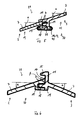
- Fig. 5 to 11 show in detail the formation of the parting line 4 as a tongue and groove joint 18th
- Fig. 5 shows the parting line 4 for the bottom wall 7 according to Fig. 2
- a sealing rib 11 is provided, which is made in one piece on the higher-lying portion 12 of the bottom wall 7 and the parting line 4 overlaps.
- the sealing rib 11 rests on the lower portion 13 of the bottom wall 7.
- the condensate flows on the upper side 29 of the bottom wall 7 from the higher lying portion 12 of the bottom wall 7 via the sealing rib 11 to the deeper portion 13 of the bottom wall 7.
- splash water if ever, only temporarily penetrate into the parting line 4.
- a sealing lip 19 is provided on each housing part 2, 3.
- the sealing lips 19 are partially formed by the tongue and groove joint 18 and are enclosed by an optional shrink tube 16 or an optional shrink film 17.
- the shrink tube 16 or the shrink film 17 are used for additional sealing of the parting line. 4
- the two sealing lips 19 mechanical fixing, z.
- clamps (not shown), be positioned, which compress the two housing parts 2, 3 and also fasten the shrink tube 16 or the shrink film 17.
- the inclination angle ⁇ of the bottom wall 7 is greater than 17 °.
- a, preferably elastic, clamping profile 40 can be pushed over the two sealing lips 19.
- the cross-sectionally approximately C-shaped clamping profile 40 is completely and not only selectively arranged along the sealing lips 19, so that in an emergency drainage channel 39 condensate can collect, which has penetrated through the tongue and groove joint 18. This collected in the emergency gutter 39 water is passed to a condensate drain (not shown), so that the condensation can do no harm.
- the clamping profile 40 presses the two housing parts 2, 3 together and seals in addition.
- the geometry of the clamping profile 40 is dimensioned such that due to an elastic deformation both housing parts 2, 3 are compressed.
- Fig. 6 to 11 show the parting line 4 for the bottom wall 7 according to 3 and 4 ,
- the housing part 3 belonging to the bottom wall 7 is provided with a sealing rib 11 ( Fig. 6 ).
- One end of the sealing rib 11 has a drip tip 15, so that from the top of the refrigerant evaporator 4 falling on the parting line 4 condensate drops can not impinge directly on the parting line 4 and condensate drops controlled at a distance from the parting line 4 on the top 29 of the left Housing part 2 belonging bottom wall 7 fall.
- a cavity 14 is formed between the sealing rib 11 with drip nose 15 and the bottom wall 7 belonging to the left-hand housing part 2.
- Bottom wall 7 at the parting line 4 below the drip 15 should be more than 0 °, ie the bottom wall 7 below the drip 15 should have a sloping slope away from the parting line 4, so that the condensation on the bottom wall 7 below the drip 15 of the parting line 4 drains off.
- the inclination of the bottom wall 7 on both sides of the parting line 4 should be greater than 17 °, so that the condensation even at an inclination of the motor vehicle, z. B. in slope sections, can flow.
- the inclination angle ⁇ is in Fig. 6 equal to the angle of inclination ⁇ .
- the third embodiment ( Fig. 7 ) of the parting line 4 differs from the second embodiment ( Fig. 6 ) by an additional sealing rib 31, which fills the cavity 14 between the sealing rib 11 and belonging to the left housing part 2 bottom wall 7.
- the sealing rib 11 and the additional sealing rib 31 can optionally be enclosed by a shrinking tube 16 or a shrinking foil 17 for sealing the parting line.
- the shrink tube 16 or the shrink film 17 is in Fig. 7 dash-dotted in the un shrunk state shown.
- the fourth embodiment ( Fig. 8 . 9 ) of the parting line 4 differs from the first embodiment ( Fig. 5 ) characterized in that the belonging to the right housing part 3 bottom wall 7 is not inclined to the parting line 4, but from the parting line 4, ie a roof profile is present.
- the condensate impinging on the sealing rib 11 flows on the bottom wall 7, which is assigned to the left housing part 2, as well as on the bottom wall 7, which is formed by the right housing part 3, in the opposite direction.
- two to four of the parting line 4 according to Fig. 6 to 9 can, analogously to the first embodiment, optionally the two sealing lips 19 on the underside 30 of the bottom wall 7 of the shrink tube 16 or the shrink film 17 or the clamping profile 40 to be enclosed and preferably an emergency drainage channel 39 may be formed. If no recess is formed as an emergency drainage channel 39 in one or both sealing lips 19, the emergency drainage channel 39 can also be formed by an elongated cavity between the sealing lips 19 and the clamping profile 40, the clamping profile 40 being spaced from the two sealing lips 19 in at least one partial area has (not shown).
- Fig. 10 shows a cross section of the parting line 4 in a fifth embodiment of the bottom wall 7.
- the parting line 4 is formed on the bottom side of the tongue and groove joint 18 with two sealing lips 19.
- the sealing rib 11 and the additional sealing rib 31 are formed parallel to one another at a distance from each other, so that a gap 41 is formed.
- an elastic clamping profile 40 is arranged made of plastic, which surround the sealing rib 11 and the additional sealing rib 31.
- the clamping profile 40 replaces z. B.
- the arranged in the gap 41 part of the clamping profile 40 of the sealing rib 11 and the additional sealing rib 31 is clamped under pressure and deformed due to the elastic properties of the clamping profile 40.
- the clamping profile 40 seals the parting line 4 in the region of the gap 41.
- the outside of the sealing rib 11 and the additional sealing rib 31 arranged part of the clamping profile 40 keeps away from the parting line 4 condensation.
- the tongue and groove joint 18 can also be dispensed with the tongue and groove joint 18 (not shown).
- An unillustrated embodiment differs from the fifth embodiment according to FIG Fig. 10 in that between the sealing rib 11 and the additional sealing rib 31, the Klemmprofl 40 is not arranged and the sealing rib 11 and the additional sealing rib 31 without gap 41 are directly adjacent to each other at the vertical parting line 4.
- the clamping profile 40 is C-shaped in section and presses the sealing rib 11 against the additional sealing rib 31st
- Fig. 11 is in a sixth embodiment, a supplement to the second embodiment according to Fig. 6 shown.
- the cross-sectionally C-shaped clamping profile 40 is turned up so that condensation is kept away from the parting line 4 between the left and right housing part 2, 3.
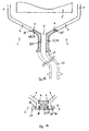
- Fig. 12 shows a horizontal section through the housing 1 and a plan view of the bottom wall 7.
- the bottom wall 7 is formed by the left and right housing part 2, 3.
- the parting line 4 between the left and right housing part 2, 3 is sealed by means of an elastic sealing element 34 as a sealing means 33 ( Fig. 12 to 16 ).
- the drain opening 8 is formed by the elastic sealing element 34 ( Fig. 12 . 13 ).
- a drain hose 35 can also be integrated as a component part of the sealing element 34, preferably in one piece, which in Fig. 11 is shown in dashed lines.
- the two housing parts 2, 3 are connected to the bottom wall 7 at two joints 4 exclusively with the elastic sealing element 34, ie there is no direct contact between the bottom wall 7 of the two housing parts 2, 3 on ( Fig. 13, 14th ).
- the bottom wall 7 of the respective housing parts 2, 3 is indirectly connected by the elastic sealing element 34.
- the elastic sealing element 34 also forms part of the bottom wall 7.
- latching shoulders 36 are formed, which are enclosed by a clamp 37 (FIG. Fig. 12 . 14 ).
- the clamp 37 exerts a compressive force on the elastic sealing element 34 so that the elastic sealing element 34 seals reliably and securely.
- a heat-shrinkable tube 16 or a shrink-wrap 17 may be attached to the latching hooks 36 (not shown).
- FIG. 15 From a certain distance of the parting line 4 of the drain opening 8, this is according to Fig. 15 educated.
- a tongue and groove joint 18 connects directly to the bottom housing part 2 belonging to the bottom wall 7 and formed by the right housing part 3 bottom wall 7.
- the elastic sealing element 34 is inserted into two recesses 38 formed by the bottom wall 7 above the tongue and groove joint 18. In this case, a compressive force is exerted on the elastic sealing element 34 because the sealing element 34 has an excess with respect to the recesses 38.
- the tongue and groove joint 18 on the bottom wall 7 according to Fig. 15 is necessary because the connection according to Fig. 14 has a lower mechanical stability.
- Fig. 16 a perspective view of the elastic sealing element 34 is shown.
- the existing on the mechanical sealing element 34 groove and spring connection 18 according to FIGS. 13 and 14 is in Fig. 14 not shown.
Landscapes
- Physics & Mathematics (AREA)
- Thermal Sciences (AREA)
- Engineering & Computer Science (AREA)
- Mechanical Engineering (AREA)
- Air-Conditioning For Vehicles (AREA)
Applications Claiming Priority (1)
| Application Number | Priority Date | Filing Date | Title |
|---|---|---|---|
| DE102007057168 | 2007-11-26 |
Publications (3)
| Publication Number | Publication Date |
|---|---|
| EP2062761A2 true EP2062761A2 (fr) | 2009-05-27 |
| EP2062761A3 EP2062761A3 (fr) | 2009-07-15 |
| EP2062761B1 EP2062761B1 (fr) | 2011-02-16 |
Family
ID=40157717
Family Applications (1)
| Application Number | Title | Priority Date | Filing Date |
|---|---|---|---|
| EP08020504A Not-in-force EP2062761B1 (fr) | 2007-11-26 | 2008-11-26 | Dispositif de climatisation de véhicule automobile |
Country Status (2)
| Country | Link |
|---|---|
| EP (1) | EP2062761B1 (fr) |
| DE (2) | DE102008059085A1 (fr) |
Cited By (6)
| Publication number | Priority date | Publication date | Assignee | Title |
|---|---|---|---|---|
| EP2284027A3 (fr) * | 2009-08-14 | 2011-08-03 | Behr GmbH & Co. KG | Dispositif de climatisation d'un véhicule |
| EP2514617A3 (fr) * | 2011-04-20 | 2013-01-02 | Behr GmbH & Co. KG | Climatisation de véhicule automobile |
| EP2378218A3 (fr) * | 2010-04-15 | 2015-01-07 | Behr GmbH & Co. KG | Installation de climatisation |
| FR3095160A1 (fr) * | 2019-04-17 | 2020-10-23 | Valeo Systemes Thermiques | Boîtier de protection étanche pour le domaine automobile |
| US20220049907A1 (en) * | 2018-12-19 | 2022-02-17 | Valeo Systemes Thermiques | Sealing device for a motor vehicle heat exchanger |
| CN116985854A (zh) * | 2023-07-31 | 2023-11-03 | 中铁城建集团有限公司 | 一种地铁通风空调排水机构 |
Families Citing this family (4)
| Publication number | Priority date | Publication date | Assignee | Title |
|---|---|---|---|---|
| SI2168796T1 (sl) | 2008-09-26 | 2013-05-31 | Valeo Klimasysteme Gmbh | Klimatska naprava za vozilo |
| DE102009057869A1 (de) * | 2009-12-11 | 2011-06-16 | Behr Gmbh & Co. Kg | Gehäuse für eine Kraftfahrzeugklimaanlage und Kraftfahrzeugklimaanlage |
| DE102016202444A1 (de) | 2016-02-17 | 2017-08-17 | Mahle International Gmbh | Klimaanlage eines Kraftfahrzeugs sowie Kraftfahrzeug |
| DE102017217628A1 (de) * | 2017-10-04 | 2019-04-04 | BSH Hausgeräte GmbH | Haushaltskältegerät mit einem endseitig flexiblen Ablaufrohr |
Citations (2)
| Publication number | Priority date | Publication date | Assignee | Title |
|---|---|---|---|---|
| US5954578A (en) | 1996-08-05 | 1999-09-21 | Denso Corporation | Air conditioner for a vehicle |
| EP1122103A2 (fr) | 2000-02-03 | 2001-08-08 | Calsonic Kansei Corporation | Appareil de conditionnement pour véhicule |
Family Cites Families (3)
| Publication number | Priority date | Publication date | Assignee | Title |
|---|---|---|---|---|
| DE9420291U1 (de) * | 1994-12-19 | 1995-10-19 | Siemens AG, 80333 München | Gehäuse aus zumindest zwei mittels einer Nut-Feder-Verbindung zusammensetzbaren Gehäuseteilen |
| FR2761013B1 (fr) * | 1997-03-18 | 1999-06-18 | Valeo Climatisation | Boitier d'appareil de chauffage-climatisation pour vehicule automobile |
| FR2769694B1 (fr) * | 1997-10-14 | 2000-01-28 | Valeo Climatisation | Boitier de dispositif de chauffage-climatisation pour vehicule automobile, comportant des moyens incorpores de recueil des condensats de l'evaporateur du climatiseur |
-
2008
- 2008-11-26 EP EP08020504A patent/EP2062761B1/fr not_active Not-in-force
- 2008-11-26 DE DE102008059085A patent/DE102008059085A1/de not_active Withdrawn
- 2008-11-26 DE DE502008002602T patent/DE502008002602D1/de active Active
Patent Citations (2)
| Publication number | Priority date | Publication date | Assignee | Title |
|---|---|---|---|---|
| US5954578A (en) | 1996-08-05 | 1999-09-21 | Denso Corporation | Air conditioner for a vehicle |
| EP1122103A2 (fr) | 2000-02-03 | 2001-08-08 | Calsonic Kansei Corporation | Appareil de conditionnement pour véhicule |
Cited By (8)
| Publication number | Priority date | Publication date | Assignee | Title |
|---|---|---|---|---|
| EP2284027A3 (fr) * | 2009-08-14 | 2011-08-03 | Behr GmbH & Co. KG | Dispositif de climatisation d'un véhicule |
| EP2378218A3 (fr) * | 2010-04-15 | 2015-01-07 | Behr GmbH & Co. KG | Installation de climatisation |
| EP2514617A3 (fr) * | 2011-04-20 | 2013-01-02 | Behr GmbH & Co. KG | Climatisation de véhicule automobile |
| US20220049907A1 (en) * | 2018-12-19 | 2022-02-17 | Valeo Systemes Thermiques | Sealing device for a motor vehicle heat exchanger |
| US11859926B2 (en) * | 2018-12-19 | 2024-01-02 | Valeo Systemes Thermiques | Sealing device for a motor vehicle heat exchanger |
| FR3095160A1 (fr) * | 2019-04-17 | 2020-10-23 | Valeo Systemes Thermiques | Boîtier de protection étanche pour le domaine automobile |
| CN116985854A (zh) * | 2023-07-31 | 2023-11-03 | 中铁城建集团有限公司 | 一种地铁通风空调排水机构 |
| CN116985854B (zh) * | 2023-07-31 | 2024-04-16 | 中铁城建集团有限公司 | 一种地铁通风空调排水机构 |
Also Published As
| Publication number | Publication date |
|---|---|
| DE102008059085A1 (de) | 2009-07-09 |
| DE502008002602D1 (de) | 2011-03-31 |
| EP2062761A3 (fr) | 2009-07-15 |
| EP2062761B1 (fr) | 2011-02-16 |
Similar Documents
| Publication | Publication Date | Title |
|---|---|---|
| EP2062761B1 (fr) | Dispositif de climatisation de véhicule automobile | |
| EP1437560B1 (fr) | Condensateur avec collecteur et capuchon protecteur | |
| DE102010062406B4 (de) | Klimagerät für ein Fahrzeug | |
| EP3283353B1 (fr) | Ensemble formant capot de tablier pour un véhicule automobile | |
| EP2514617B1 (fr) | Climatisation de véhicule automobile | |
| DE102014109811B4 (de) | Luftleitvorrichtung zur Abluftführung | |
| DE102014112535B4 (de) | Kraftfahrzeugklimaanlage mit lösbar verbundenem Filterdeckel | |
| DE102007013690A1 (de) | Gehäuseteil für eine Heizungs- und/oder Klimaanlage | |
| EP1504803A1 (fr) | Filtre à air, notamment pour l' habitacle intérieur d' un véhicule automobile | |
| DE4410120C2 (de) | Klimaanlage für ein Kraftfahrzeug | |
| EP4137339A1 (fr) | Dispositif d'évacuation d'eau pour un véhicule | |
| DE102008007915A1 (de) | Deckel-Gehäuse-Anordnung, insbesondere für einen Filter eines Fahrzeug-Belüftungssystems | |
| DE102016203871A1 (de) | Klimaanlage | |
| DE10216868A1 (de) | Kunststoffölabweiser | |
| DE102015100093B4 (de) | Dichtungselement für ein Gehäuse eines Klimatisierungssystems eines Kraftfahrzeugs | |
| DE102017221771A1 (de) | Heizungs- oder Klimaanlage | |
| DE102014018299B4 (de) | Arbeitsmaschine mit Kabine und Verfahren zur Einstellung eines Ventils einer Arbeitsmaschine | |
| DE102016209628A1 (de) | Heizungs-, Belüftungs- oder Klimaanlage | |
| DE102008045595B4 (de) | Kraftfahrzeug-Luftfiltersystem und zugehöriges Montageverfahren | |
| EP1669224B1 (fr) | Climatisateur comprenant un évaporateur avec une bouche d'écoulement de l'eau de condensation | |
| DE19753562A1 (de) | Vorrichtung zur Montage und Halterung eines Verdampfers in einem Gehäuse einer Heizungs- und Klimaanlage | |
| DE102021112524A1 (de) | Verdampfereinheit | |
| WO2023285361A1 (fr) | Système de chauffage, de ventilation et/ou de climatisation | |
| DE69718978T2 (de) | Behälter zum Sammeln von Kondensat und Kühlgerät mit solchem Behälter | |
| EP1512564B1 (fr) | Dispositif de climatisation pour véhicule automobile |
Legal Events
| Date | Code | Title | Description |
|---|---|---|---|
| PUAI | Public reference made under article 153(3) epc to a published international application that has entered the european phase |
Free format text: ORIGINAL CODE: 0009012 |
|
| AK | Designated contracting states |
Kind code of ref document: A2 Designated state(s): AT BE BG CH CY CZ DE DK EE ES FI FR GB GR HR HU IE IS IT LI LT LU LV MC MT NL NO PL PT RO SE SI SK TR |
|
| AX | Request for extension of the european patent |
Extension state: AL BA MK RS |
|
| PUAL | Search report despatched |
Free format text: ORIGINAL CODE: 0009013 |
|
| AK | Designated contracting states |
Kind code of ref document: A3 Designated state(s): AT BE BG CH CY CZ DE DK EE ES FI FR GB GR HR HU IE IS IT LI LT LU LV MC MT NL NO PL PT RO SE SI SK TR |
|
| AX | Request for extension of the european patent |
Extension state: AL BA MK RS |
|
| 17P | Request for examination filed |
Effective date: 20100115 |
|
| 17Q | First examination report despatched |
Effective date: 20100223 |
|
| AKX | Designation fees paid |
Designated state(s): DE FR |
|
| GRAP | Despatch of communication of intention to grant a patent |
Free format text: ORIGINAL CODE: EPIDOSNIGR1 |
|
| GRAS | Grant fee paid |
Free format text: ORIGINAL CODE: EPIDOSNIGR3 |
|
| GRAA | (expected) grant |
Free format text: ORIGINAL CODE: 0009210 |
|
| AK | Designated contracting states |
Kind code of ref document: B1 Designated state(s): DE FR |
|
| REF | Corresponds to: |
Ref document number: 502008002602 Country of ref document: DE Date of ref document: 20110331 Kind code of ref document: P |
|
| REG | Reference to a national code |
Ref country code: DE Ref legal event code: R096 Ref document number: 502008002602 Country of ref document: DE Effective date: 20110331 |
|
| PLBE | No opposition filed within time limit |
Free format text: ORIGINAL CODE: 0009261 |
|
| STAA | Information on the status of an ep patent application or granted ep patent |
Free format text: STATUS: NO OPPOSITION FILED WITHIN TIME LIMIT |
|
| 26N | No opposition filed |
Effective date: 20111117 |
|
| REG | Reference to a national code |
Ref country code: DE Ref legal event code: R097 Ref document number: 502008002602 Country of ref document: DE Effective date: 20111117 |
|
| REG | Reference to a national code |
Ref country code: FR Ref legal event code: ST Effective date: 20120731 |
|
| PG25 | Lapsed in a contracting state [announced via postgrant information from national office to epo] |
Ref country code: FR Free format text: LAPSE BECAUSE OF NON-PAYMENT OF DUE FEES Effective date: 20111130 |
|
| REG | Reference to a national code |
Ref country code: DE Ref legal event code: R082 Ref document number: 502008002602 Country of ref document: DE Representative=s name: GRAUEL, ANDREAS, DIPL.-PHYS. DR. RER. NAT., DE |
|
| REG | Reference to a national code |
Ref country code: DE Ref legal event code: R081 Ref document number: 502008002602 Country of ref document: DE Owner name: MAHLE INTERNATIONAL GMBH, DE Free format text: FORMER OWNER: BEHR GMBH & CO. KG, 70469 STUTTGART, DE Effective date: 20150303 Ref country code: DE Ref legal event code: R082 Ref document number: 502008002602 Country of ref document: DE Representative=s name: GRAUEL, ANDREAS, DIPL.-PHYS. DR. RER. NAT., DE Effective date: 20150303 |
|
| PGFP | Annual fee paid to national office [announced via postgrant information from national office to epo] |
Ref country code: DE Payment date: 20181203 Year of fee payment: 11 |
|
| REG | Reference to a national code |
Ref country code: DE Ref legal event code: R119 Ref document number: 502008002602 Country of ref document: DE |
|
| PG25 | Lapsed in a contracting state [announced via postgrant information from national office to epo] |
Ref country code: DE Free format text: LAPSE BECAUSE OF NON-PAYMENT OF DUE FEES Effective date: 20200603 |