EP2063023A2 - Dispositif et procédé de changement de toile d'une machine à papier - Google Patents
Dispositif et procédé de changement de toile d'une machine à papier Download PDFInfo
- Publication number
- EP2063023A2 EP2063023A2 EP08169104A EP08169104A EP2063023A2 EP 2063023 A2 EP2063023 A2 EP 2063023A2 EP 08169104 A EP08169104 A EP 08169104A EP 08169104 A EP08169104 A EP 08169104A EP 2063023 A2 EP2063023 A2 EP 2063023A2
- Authority
- EP
- European Patent Office
- Prior art keywords
- fabric
- paper machine
- cylinder
- clothing
- chair
- Prior art date
- Legal status (The legal status is an assumption and is not a legal conclusion. Google has not performed a legal analysis and makes no representation as to the accuracy of the status listed.)
- Withdrawn
Links
- 239000004744 fabric Substances 0.000 title claims abstract description 74
- 238000000034 method Methods 0.000 title claims abstract description 24
- 238000003780 insertion Methods 0.000 claims description 7
- 230000037431 insertion Effects 0.000 claims description 7
- DNJIEGIFACGWOD-UHFFFAOYSA-N ethanethiol Chemical compound CCS DNJIEGIFACGWOD-UHFFFAOYSA-N 0.000 claims description 4
- 239000003351 stiffener Substances 0.000 claims description 4
- 239000000725 suspension Substances 0.000 claims description 2
- 238000005452 bending Methods 0.000 description 5
- 206010003497 Asphyxia Diseases 0.000 description 3
- 238000009432 framing Methods 0.000 description 3
- 239000000969 carrier Substances 0.000 description 2
- 239000000314 lubricant Substances 0.000 description 2
- 238000010276 construction Methods 0.000 description 1
- 230000007423 decrease Effects 0.000 description 1
- 230000002093 peripheral effect Effects 0.000 description 1
- 238000000926 separation method Methods 0.000 description 1
Images



Classifications
-
- D—TEXTILES; PAPER
- D21—PAPER-MAKING; PRODUCTION OF CELLULOSE
- D21F—PAPER-MAKING MACHINES; METHODS OF PRODUCING PAPER THEREON
- D21F7/00—Other details of machines for making continuous webs of paper
- D21F7/001—Wire-changing arrangements
Definitions
- the invention relates to a device for changing a fabric of a paper machine, a method for changing the clothing and a clothing itself.
- a device which comprises a plurality of individual rollers, which served essentially to assist the collection of the clothing.
- a disadvantage of the FI-B-103421 was that the device to support the collection of the clothing included a variety of individual roles and thus items. Furthermore, had from the FI-B-103421 known roles the disadvantage of high surface pressure.
- the changing device according to the WO 2006/106178 includes a first device with a frame, a pressure chamber and a circulating belt as well as a second device of the same construction arranged under this first device.
- Each of the two devices has a pressure chamber.
- the frames of the pressure chamber absorb the forces of the upper and lower parts of the stool.
- the bands of the device are not loaded.
- a change of clothing is to be carried out, pressure is introduced into the pressure chambers.
- the introduced pressure in the pressure chamber causes the load, which was loaded on the frame in the operating state, to be transmitted to the belts and the pressure chambers.
- the frame members are thereby separated from each other as the load is transmitted from the frame members to the pressure chambers and the bands.
- a gap is created between the frame or the upper part of the chair and the lower part of the chair, through which the covering can be threaded.
- the pressure introduced into the pressure chambers is also utilized so that the introduced band can slide substantially without friction. If the fabric is guided during the change in the resulting gap between the bands of the device, the fabric can be introduced by means of the bands in the device, for example, in that a drive motor is coupled to at least one roller of the device.
- a disadvantage of the device according to the WO 2006/106178 was that the fabric could only be pulled in with the help of a lubricant without damaging the fabric.
- the object of the invention is therefore to provide a solution for a string changing device, with the disadvantages of the prior
- the technique can be avoided and with the a change of clothing without complicated further measures as in the WO 2006/106178 described, can be performed.
- the use of a lubricant should be avoided.
- a device for changing a fabric in a paper machine with a stiffening at least a first and a second half of the staging has at least a first means for applying a flat pressure on the fabric is provided and a second means for applying a flat counterpressure on the fabric, so that by applying the sheet pressure, the first and the second half of the stiffener are pressed apart and a chair opening is provided for Beschreibs CAD available and further provided at least a third means with which the fabric in a horizontal direction along the opening of the chair can be moved.
- the first device is also referred to as a top unit and the second device as a subunit.
- the first device preferably comprises a cylinder, which is supported by a support device on the first half of the chair.
- the cylinder may preferably be a hydraulic, pneumatic or electric cylinder.
- the support a slide bearing plate.
- the second support device is designed as a sliding bearing plate.
- the third device for moving the clamped-in clothing approximately horizontally in the direction of the opening of the strangulation comprises a further cylinder, which in turn may be designed as a hydraulic, pneumatic or electric cylinder.
- the first device comprises a cylinder, which is supported by a support device on the first half of the chair and connected to a pressure plate which can apply the surface pressure on the fabric.
- the first device opposite the second device again has a counter-plate, which is supported by a further support means on the second half of the chair.
- This further support means may in turn comprise a cylinder.
- a flat pressure can be applied to the fabric over a plate. If now the cylinder of the first device extended, the stench is raised. The clothing can now be changed.
- a horizontal process can be done by another cylinder.
- the changing device according to the invention is used in a paper machine with a press and / or wire section for changing screens or felts use.
- the invention also provides a method for drawing a string.
- the method first the fabric is stretched in front of the paper machine. Then, with the aid of the first device, the upper and lower half of the stiffener are pushed apart.
- the weight of the upper half of the stool is then transferred with their superstructures over the fabric to the lower half of the stiffener.
- the invention also shows a clothing with means that avoid damage during insertion or execution.
- the fabric had lateral insertion and removal aids.
- FIG. 1 is a side view of a section of a paper machine shown, for example, a press section.
- the individual elements of the press section are received by a chair 10. Furthermore, the circumferential covering, for example a felt in the press section of the paper machine, can be seen. In the present embodiment, only the peripheral top felt 20 is completely shown, the circumferential bottom felt 22 only partially. How out FIG. 1 to see, in order to exchange the top felt 20, the connection of the individual parts of the chair 10.1, 10.2, be solved and the individual parts of the chair 10.1, 10.2 be raised, so that there are openings 30.1, 30.2, 30.3, through which the fabric at a change can be passed.
- the stool openings are generally provided on the leader side of the paper machine by incorporating cantilever or flex beams extending from the leader side to the drive side and beyond, in addition to the traverses, in the paper machine. Such carriers are in the schematic view according to FIG. 2 shown.
- the carriers 40.1, 40.2 required for raising the framing parts run from the driver's side 100 to the drive side 120 of the paper machine.
- the supports 40.1, 40.2 are in turn anchored with supports 110.1, 110.2 either on the ceiling or on the ground, so that the forces of the stasis on the supports in the ground or in the ceiling are introduced.
- the resulting on the concern of the wearer openings on the gnatulites are in FIG. 2 also shown.
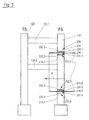
- FIG. 3 a schematic plan view of a paper machine or a part of a paper machine 100 from the driver side to the drive side.
- the leader side (FS) 110 is connected to the drive side (TS) 120 of the paper machine via traverse carrier 130.1, 130.2.
- TS drive side
- the device according to the invention is used to press apart the driver-side structural parts in the region of the device according to the invention with an upper and lower unit, so that an opening is made available. The fabric can then be inserted into this opening.
- the upper units 212.1, 212.3 for applying a flat pressure to the clothing comprise a first device, preferably a hydraulically raisable and lowerable cylinder 214.1, 214.2.
- the cylinders 214.1, 214.2 lowered and press surface on the fabric 216.1, 216.2.
- the clothing is then clamped between the cylinders 214.1, 214.2 and the counter plates 218.1, 218.2 opposite the cylinders.
- Both the upper units 212.1, 212.3 with cylinders 214.1, 214.2 and subunits 212.2, 212.4 are mounted on a slide plate 222.1, 222.2, 222.3, 222.4 and can be moved by means of, for example, another cylinder 224.1, 224.2 in a drawn horizontal direction H for pulling the fabric.
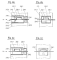
- FIGS. 4a and 4b show a first embodiment of the device according to the invention when pulling the fabric into the paper machine.
- the device is subdivided into an upper unit 212.1 and a subunit 212.2. Same components as in Figure 3 are marked with the same reference numbers.
- To pull in the clothing first the pressure chamber 215 of the cylinder 214.1 is subjected to a pressure medium.
- the piston 226.1 of the cylinder 214.1 extends, which causes the upper and the lower half of the suspension 230.1, 230.2 is pushed apart.
- the weight of the upper half of the cage with its superstructures is transferred in such a case on the fabric 216.1 on the lower half of the steamer.
- the collection of the clothing 216.1 in the paper machine is carried out in that the clamped clothing 216.1 together with the means for applying the counterforce, here the lower device 212.2 in the form of a so-called counter-plate or a counter-holder by means of additional cylinders 224.1, 224.2, as hydraulic -, electric or pneumatic cylinder can be designed, in the horizontal direction along the sliders 222.1, 222.2 slides and pulls in this way, the fabric a little way into the paper machine.
- FIGS. 4c to 4d show the process of the cylinders, which are responsible for the horizontal movement, in the starting position after the fabric has been fed into the paper machine.
- the piston 226.1 of the cylinder of the first device is raised, for example by the pressure medium being discharged in the pressure chamber.
- the piston is then no longer in contact with the fabric.
- the upper stiffening part 230.1 lowers onto the covering 216.1.
- the additional cylinders, the horizontal method of both the cylinder of the upper unit as well as the counter plate of the subunit in the FIGS. 4a and 4b are caused to be returned along the slide plate in their initial positions.
- the cylinder and the anvil are returned to the starting position, so the Einziehvorgang according to the FIGS. 4a and 4b start again. In this way, the entire clothing is successively pulled into the paper machine.
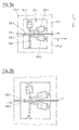
- the first device or the upper unit 312.1 comprises two cylinders 300.1, 305.1, which are fastened to a stiffening half 310.1.
- the other end of the cylinder is connected to a pressure plate 320.1, which can exert a surface-acting force on the fabric 316.
- the cylinder 300.1 essentially performs a vertical movement in the vertical direction V and the cylinder 305.1 substantially horizontal movement in the direction H.
- the cylinders 300.1, 305.1 of the first device which are connected to the upper half of the stool 310.1, are adjusted so that the pressure plate 320.1 does not come into contact with the fabric.
- the fabric itself is trapped between the printing plates 320.1, 330.1.
- the clothing clamped between the printing plates is now drawn into the paper machine by horizontal movement.
- the cylinder connected to the first half of the chair is retracted, whereby the first half of the chair is lowered onto the second half of the chair.
- the printing plates 320.1, 330.1 spent again in the starting position. Then the cycle can be repeated.
- the threading process can start anew.
- the stroke of the horizontally operating cylinder is preferably greater than the length of Printing plates. This has the advantage that during the first stroke the fabric can be gripped over the full surface of the printing plates with a stroke. As a result, a low stress on the clothing to be recovered is achieved.
- FIGS. 6a and 6b is an alternative embodiment of a second embodiment of the invention, as in the FIGS. 5a and 5b shown, shown.
- the same components are assigned the same reference numbers.
- the first device which is arranged on the upper half of the chair, is similar to the FIGS. 5a and 5b executed. She also works in an analogous way.
- a so-called Wälzwagen 400 is provided, which is characterized in that it comprises a plurality of rollers 405 which are connected to form an endless belt 410.
- the rollers 405 which are connected to form an endless belt 410, again wrapped around the entire circumference with a chain 420.
- the rollers rotate about a fixed core 425.
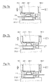
- FIGS. 7a to 7c is given a particularly preferred embodiment of the invention.
- Same components as in Fig. 4a to 4d are assigned the same reference numbers.
- the Design of a paper machine according to FIGS. 7a to 7c In addition, cylinder 500.1, 500.2 on, which can serve to lift the Friction parts.
- FIG. 7c shows the end of the threading process.
- the covering between the piston and the counterplate must be removed.
- cylinder 500.1 is extended and the upper and lower parts of the frame are pushed apart. Due to the resulting gap S, the fabric can be easily removed from the changing device.
- FIGS. 8a to 8c an alternative embodiment of a Einziehvorganges is shown, in which can be dispensed with additional cylinder on the outside of the stiffening. Same components as in the FIGS. 4a to 4d are with the same reference numerals.
- the two parts of the framing are first pressed apart by pressurizing the piston in the cylinder at the separation point on the stiffening. It creates a gap in this way. Through this gap, the fabric to be changed can be pushed to the front of the piston 226.1, which rests on the back plate.
- the piston 226.1 retracted into the cylinder.
- the parting line between upper and lower stiffening closes and the weight of the entire stench lies on the covering 216.
- the surface of the parting line 600 is at least as large as that of the piston 226.1, in order to avoid that in the region of the parting line 600 a higher surface load on the clothing 216 is as in the area of the piston 226.1.
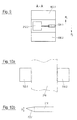
- FIG. 9 is a section along A - A in FIG. 8c shown. Clearly visible is the square shaped counter-plate, which exerts a surface-acting force on the fabric.
- the horizontally movable cylinder is designated 224.1.
- the parting line 600 in FIG. 8a is located to the leader's side offset to the left of the upper unit 214.1.
- Two separating joints 600.1, 600.2) are shown.
- FIGS. 10a-10b an alternative variant is shown, with which the covering can be protected, if at the beginning the covering can not be pulled completely under the lifting surface 320.1.
- FIG. 10a is shown how damage to the fabric especially at the first and last stroke for feeding alternatively to the in the FIGS. 7 to 9 described solutions, however, in contrast to FIG. 8a are not offset to the driver's side, but are parallel to the cylinder 224 in the machine direction P 1 or P 2 , can be avoided.
- an approximately equally thick piece 700.1, 700.2 of other clothing is stapled to the edge on both sides of the clothing 216.
- the other pieces 700.1, 700. 2 of the clothing are also referred to as lateral insertion and Ausfactudgen.
- the insertion and removal aids preferably have substantially the same thickness as the covering or the felt which is used in the paper machine, for example for dewatering.
- the stitched to the edge of the fabric felts can then be damaged when pulled by too high pressure, but this is not critical, since these parts can be removed again at the end of the pulling-in process for the fabric.
- FIG. 10a shows a plan view of a part of the fabric with laterally arranged input and Aus slaughter time
- FIG. 10b a sectional view. It can be clearly seen that the thickness of the fabric to the edge, ie to the input and export parts out, decreases, in the area in which the input and export parts are sewn to the fabric, but essentially matches.
- a device is specified for the first time, which allows to draw in a simple manner a stringing in a press or wire section, wherein the use of cantilevers is avoided.
Landscapes
- Treatment Of Fiber Materials (AREA)
Applications Claiming Priority (1)
| Application Number | Priority Date | Filing Date | Title |
|---|---|---|---|
| DE102007047859A DE102007047859A1 (de) | 2007-11-26 | 2007-11-26 | Vorrichtung zum Wechseln einer Bespannung einer Papiermaschine |
Publications (2)
| Publication Number | Publication Date |
|---|---|
| EP2063023A2 true EP2063023A2 (fr) | 2009-05-27 |
| EP2063023A3 EP2063023A3 (fr) | 2009-07-01 |
Family
ID=40386095
Family Applications (1)
| Application Number | Title | Priority Date | Filing Date |
|---|---|---|---|
| EP08169104A Withdrawn EP2063023A3 (fr) | 2007-11-26 | 2008-11-14 | Dispositif et procede de changement de toile d'une machine a papier |
Country Status (2)
| Country | Link |
|---|---|
| EP (1) | EP2063023A3 (fr) |
| DE (1) | DE102007047859A1 (fr) |
Cited By (7)
| Publication number | Priority date | Publication date | Assignee | Title |
|---|---|---|---|---|
| WO2011056113A1 (fr) * | 2009-11-06 | 2011-05-12 | Metso Paper, Inc. | Appareil d'insertion ou de retrait d'habillage dans une machine industrielle |
| AT12472U1 (de) * | 2010-10-21 | 2012-06-15 | Metso Paper Inc | Vorrichtung zum wechseln eines bands in einer faserbahnmaschine sowie mit dieser vorrichtung ausgestaltete faserbahnmaschine |
| CN103774484A (zh) * | 2012-10-25 | 2014-05-07 | 美卓造纸机械公司 | 纤维幅材处理装置 |
| DE102015211300A1 (de) * | 2015-06-19 | 2016-05-25 | Voith Patent Gmbh | Einrichtung und Verfahren zum Einbringen einer Bespannung in eine Bahnbildungsmaschine |
| DE102016201895A1 (de) | 2016-02-09 | 2017-01-05 | Voith Patent Gmbh | Vorrichtung und Verfahren zum Wechseln einer Bespannung einer Papiermaschine |
| DE102016211359A1 (de) | 2016-06-24 | 2017-10-05 | Voith Patent Gmbh | Vorrichtung und Verfahren zum Wechseln einer Bespannung einer Papiermaschine |
| WO2017220243A1 (fr) | 2016-06-24 | 2017-12-28 | Voith Patent Gmbh | Dispositif et procédé pour changer un habillage de machine à papier |
Families Citing this family (3)
| Publication number | Priority date | Publication date | Assignee | Title |
|---|---|---|---|---|
| DE102015223661A1 (de) * | 2015-11-30 | 2017-05-18 | Voith Patent Gmbh | Vorrichtung zur herstellung einer faserstoffbahn |
| AT526229B1 (de) * | 2023-05-05 | 2024-01-15 | Andritz Ag Maschf | Maschine und verfahren zur herstellung einer faserstoffbahn |
| DE102024121625A1 (de) * | 2024-07-30 | 2025-08-21 | Voith Patent Gmbh | Siebpartie einer Maschine zur Herstellung einer Faserstoffbahn und Verfahren zum Einziehen eines Siebes |
Citations (2)
| Publication number | Priority date | Publication date | Assignee | Title |
|---|---|---|---|---|
| FI103421B (fi) | 1997-10-30 | 1999-06-30 | Valmet Corp | Menetelmä ja laite paperikoneessa kudoksen vaihtamiseksi |
| WO2006106178A1 (fr) | 2005-04-05 | 2006-10-12 | Metso Paper, Inc. | Procede et dispositif de changement de toile dans une machine a papier ou carton |
Family Cites Families (2)
| Publication number | Priority date | Publication date | Assignee | Title |
|---|---|---|---|---|
| SE439652B (sv) * | 1983-10-25 | 1985-06-24 | Nordiskafilt Ab | Monteringsanordning vid pappersmaskinfilt |
| EP1820898A1 (fr) * | 2006-02-20 | 2007-08-22 | Ichikawa Co.,Ltd. | Dispositif pour installer une toile dans une machine à papier et procédé de fabrication du dispositif |
-
2007
- 2007-11-26 DE DE102007047859A patent/DE102007047859A1/de not_active Withdrawn
-
2008
- 2008-11-14 EP EP08169104A patent/EP2063023A3/fr not_active Withdrawn
Patent Citations (2)
| Publication number | Priority date | Publication date | Assignee | Title |
|---|---|---|---|---|
| FI103421B (fi) | 1997-10-30 | 1999-06-30 | Valmet Corp | Menetelmä ja laite paperikoneessa kudoksen vaihtamiseksi |
| WO2006106178A1 (fr) | 2005-04-05 | 2006-10-12 | Metso Paper, Inc. | Procede et dispositif de changement de toile dans une machine a papier ou carton |
Cited By (13)
| Publication number | Priority date | Publication date | Assignee | Title |
|---|---|---|---|---|
| WO2011056113A1 (fr) * | 2009-11-06 | 2011-05-12 | Metso Paper, Inc. | Appareil d'insertion ou de retrait d'habillage dans une machine industrielle |
| CN102597368A (zh) * | 2009-11-06 | 2012-07-18 | 梅特索纸业有限公司 | 用于插入或移除工业机器中的罩的设备 |
| US8574401B2 (en) | 2009-11-06 | 2013-11-05 | Metso Paper, Inc. | Apparatus for inserting or removing a clothing in an industrial machine |
| CN102597368B (zh) * | 2009-11-06 | 2014-12-17 | 梅特索纸业有限公司 | 插入或移除织物的方法、设备及用途、机器及改进方法 |
| AT12472U1 (de) * | 2010-10-21 | 2012-06-15 | Metso Paper Inc | Vorrichtung zum wechseln eines bands in einer faserbahnmaschine sowie mit dieser vorrichtung ausgestaltete faserbahnmaschine |
| CN103774484A (zh) * | 2012-10-25 | 2014-05-07 | 美卓造纸机械公司 | 纤维幅材处理装置 |
| DE102015211300A1 (de) * | 2015-06-19 | 2016-05-25 | Voith Patent Gmbh | Einrichtung und Verfahren zum Einbringen einer Bespannung in eine Bahnbildungsmaschine |
| DE102016201895A1 (de) | 2016-02-09 | 2017-01-05 | Voith Patent Gmbh | Vorrichtung und Verfahren zum Wechseln einer Bespannung einer Papiermaschine |
| DE102016211359A1 (de) | 2016-06-24 | 2017-10-05 | Voith Patent Gmbh | Vorrichtung und Verfahren zum Wechseln einer Bespannung einer Papiermaschine |
| WO2017220243A1 (fr) | 2016-06-24 | 2017-12-28 | Voith Patent Gmbh | Dispositif et procédé pour changer un habillage de machine à papier |
| DE102016211360A1 (de) | 2016-06-24 | 2017-12-28 | Voith Patent Gmbh | Vorrichtung und Verfahren zum Wechseln einer Bespannung einer Papiermaschine |
| CN108884636A (zh) * | 2016-06-24 | 2018-11-23 | 福伊特专利有限公司 | 用于更换造纸机的绷网的设备和方法 |
| CN108884636B (zh) * | 2016-06-24 | 2020-04-07 | 福伊特专利有限公司 | 用于更换造纸机的绷网的设备和方法 |
Also Published As
| Publication number | Publication date |
|---|---|
| DE102007047859A1 (de) | 2009-05-28 |
| EP2063023A3 (fr) | 2009-07-01 |
Similar Documents
| Publication | Publication Date | Title |
|---|---|---|
| EP2063023A2 (fr) | Dispositif et procédé de changement de toile d'une machine à papier | |
| EP0571581B1 (fr) | Presse a cylindres | |
| DE4110205C2 (de) | Walzenpresse | |
| DE102007012174B4 (de) | Rundballenpresse und Verfahren zur Änderung der Reibung an deren Seitenwänden | |
| DE19717472A1 (de) | Verfahren und Vorrichtung zum Profilbiegen mit modularen Biegestationen | |
| DE2943974C2 (de) | Pressenpartie einer Papiermaschine | |
| EP3475482B1 (fr) | Dispositif et procédé pour changer un habillage de machine à papier | |
| EP3160726B1 (fr) | Presse à châssis en c, améliorée | |
| DE102007047858A1 (de) | Vorrichtung zum Wechseln einer Bespannung einer Papiermaschine | |
| EP3782745A1 (fr) | Machine à dresser, agencement d'entretien et procédé permettant de rendre les rouleaux de dressage accessibles pour l'entretien d'une machine à dresser | |
| DE4328505C2 (de) | Cantileverbare Walze | |
| DE2635010C2 (de) | Presse zum Trocknen nasser Felle mit endlosen, seitlich abnehmbaren Filzbändern | |
| DE682688C (de) | Mehrwalzenkalander | |
| DE3242721C2 (de) | Naßpresse zum Entwässern einer laufenden Faserbahn | |
| DE102016201895A1 (de) | Vorrichtung und Verfahren zum Wechseln einer Bespannung einer Papiermaschine | |
| DE8232424U1 (de) | Preßvorrichtung zum Entwässern einer laufenden Faserbahn | |
| DE19882820B4 (de) | Verfahren und Vorrichtung zum Wechseln eines Rundfilzes | |
| DE1814066A1 (de) | Maschine zum Biegen von Blechen zwecks Herstellung von rohrfoermigen Koerpern und mit einer solchen Maschine ausgeruestete Anlage | |
| AT14017U1 (de) | Vorrichtung zum Behandeln einer Faserbahn | |
| DE102016211359A1 (de) | Vorrichtung und Verfahren zum Wechseln einer Bespannung einer Papiermaschine | |
| DE202017103053U1 (de) | Vorpresse und System zum kontinuierlichen Herstellen von Werkstoffplatten und Transportvorrichtung zum Aufnehmen des Pressenbandes | |
| WO2016034688A1 (fr) | Presse travaillant en continu et procédé de fonctionnement de telles presses | |
| DE102004046062A1 (de) | Verfahren und Vorrichtung zum Austauschen eines alten Bandes gegen ein neues Band in einer Maschine, insbesondere zum Wechsel eines Filzes in einer Papiermaschine | |
| DE1928304A1 (de) | Papiermaschinenpresse | |
| WO2024230964A1 (fr) | Machine et procédé pour la production d'une bande de matière fibreuse |
Legal Events
| Date | Code | Title | Description |
|---|---|---|---|
| PUAI | Public reference made under article 153(3) epc to a published international application that has entered the european phase |
Free format text: ORIGINAL CODE: 0009012 |
|
| AK | Designated contracting states |
Kind code of ref document: A2 Designated state(s): AT BE BG CH CY CZ DE DK EE ES FI FR GB GR HR HU IE IS IT LI LT LU LV MC MT NL NO PL PT RO SE SI SK TR |
|
| AX | Request for extension of the european patent |
Extension state: AL BA MK RS |
|
| PUAL | Search report despatched |
Free format text: ORIGINAL CODE: 0009013 |
|
| AK | Designated contracting states |
Kind code of ref document: A3 Designated state(s): AT BE BG CH CY CZ DE DK EE ES FI FR GB GR HR HU IE IS IT LI LT LU LV MC MT NL NO PL PT RO SE SI SK TR |
|
| AX | Request for extension of the european patent |
Extension state: AL BA MK RS |
|
| RIC1 | Information provided on ipc code assigned before grant |
Ipc: D21F 7/00 20060101AFI20090310BHEP |
|
| RTI1 | Title (correction) |
Free format text: DEVICE AND METHOD FOR CHANGING A FABRIC OF A PAPER MACHINE |
|
| 17P | Request for examination filed |
Effective date: 20100104 |
|
| 17Q | First examination report despatched |
Effective date: 20100208 |
|
| AKX | Designation fees paid |
Designated state(s): AT BE BG CH CY CZ DE DK EE ES FI FR GB GR HR HU IE IS IT LI LT LU LV MC MT NL NO PL PT RO SE SI SK TR |
|
| RIN1 | Information on inventor provided before grant (corrected) |
Inventor name: MUELLER, ANSGAR Inventor name: SCHMIDT, FRANK |
|
| GRAP | Despatch of communication of intention to grant a patent |
Free format text: ORIGINAL CODE: EPIDOSNIGR1 |
|
| STAA | Information on the status of an ep patent application or granted ep patent |
Free format text: STATUS: THE APPLICATION IS DEEMED TO BE WITHDRAWN |
|
| 18D | Application deemed to be withdrawn |
Effective date: 20130129 |