EP2063033A2 - Connection element, insert and cartridge - Google Patents
Connection element, insert and cartridge Download PDFInfo
- Publication number
- EP2063033A2 EP2063033A2 EP08020139A EP08020139A EP2063033A2 EP 2063033 A2 EP2063033 A2 EP 2063033A2 EP 08020139 A EP08020139 A EP 08020139A EP 08020139 A EP08020139 A EP 08020139A EP 2063033 A2 EP2063033 A2 EP 2063033A2
- Authority
- EP
- European Patent Office
- Prior art keywords
- concrete
- cartridge
- insert
- connecting element
- sliding
- Prior art date
- Legal status (The legal status is an assumption and is not a legal conclusion. Google has not performed a legal analysis and makes no representation as to the accuracy of the status listed.)
- Withdrawn
Links
- 239000004567 concrete Substances 0.000 claims abstract description 74
- 239000000463 material Substances 0.000 claims abstract description 35
- 239000002131 composite material Substances 0.000 claims abstract description 8
- 239000002023 wood Substances 0.000 claims abstract description 6
- 239000002657 fibrous material Substances 0.000 claims abstract description 3
- 239000000835 fiber Substances 0.000 claims description 23
- 239000004033 plastic Substances 0.000 claims description 7
- 229920003023 plastic Polymers 0.000 claims description 7
- 230000006835 compression Effects 0.000 claims description 4
- 238000007906 compression Methods 0.000 claims description 4
- 229920006324 polyoxymethylene Polymers 0.000 abstract description 7
- 239000011210 fiber-reinforced concrete Substances 0.000 abstract description 4
- -1 polyoxymethylene Polymers 0.000 abstract 3
- 229930040373 Paraformaldehyde Natural products 0.000 abstract 1
- 239000004952 Polyamide Substances 0.000 abstract 1
- 239000004698 Polyethylene Substances 0.000 abstract 1
- 239000004743 Polypropylene Substances 0.000 abstract 1
- 229920002647 polyamide Polymers 0.000 abstract 1
- 229920000573 polyethylene Polymers 0.000 abstract 1
- 229920001155 polypropylene Polymers 0.000 abstract 1
- 229920002994 synthetic fiber Polymers 0.000 abstract 1
- 238000009413 insulation Methods 0.000 description 9
- 238000005266 casting Methods 0.000 description 6
- 238000007639 printing Methods 0.000 description 6
- 239000012212 insulator Substances 0.000 description 4
- 239000010410 layer Substances 0.000 description 4
- 238000004519 manufacturing process Methods 0.000 description 4
- 238000005336 cracking Methods 0.000 description 3
- 238000001035 drying Methods 0.000 description 3
- 230000000694 effects Effects 0.000 description 3
- 238000009434 installation Methods 0.000 description 3
- 239000002184 metal Substances 0.000 description 3
- 239000012791 sliding layer Substances 0.000 description 3
- 238000011161 development Methods 0.000 description 2
- 230000018109 developmental process Effects 0.000 description 2
- 239000011810 insulating material Substances 0.000 description 2
- 230000010354 integration Effects 0.000 description 2
- 230000003014 reinforcing effect Effects 0.000 description 2
- 238000005507 spraying Methods 0.000 description 2
- 229930182556 Polyacetal Natural products 0.000 description 1
- 229910000831 Steel Inorganic materials 0.000 description 1
- 239000004809 Teflon Substances 0.000 description 1
- 229920006362 Teflon® Polymers 0.000 description 1
- 230000015572 biosynthetic process Effects 0.000 description 1
- 239000011248 coating agent Substances 0.000 description 1
- 238000000576 coating method Methods 0.000 description 1
- 238000010276 construction Methods 0.000 description 1
- 238000007598 dipping method Methods 0.000 description 1
- 238000006073 displacement reaction Methods 0.000 description 1
- 238000009826 distribution Methods 0.000 description 1
- 238000005516 engineering process Methods 0.000 description 1
- 230000002349 favourable effect Effects 0.000 description 1
- 230000005484 gravity Effects 0.000 description 1
- 238000010438 heat treatment Methods 0.000 description 1
- 238000003780 insertion Methods 0.000 description 1
- 230000037431 insertion Effects 0.000 description 1
- 238000002955 isolation Methods 0.000 description 1
- 239000007788 liquid Substances 0.000 description 1
- ORQBXQOJMQIAOY-UHFFFAOYSA-N nobelium Chemical compound [No] ORQBXQOJMQIAOY-UHFFFAOYSA-N 0.000 description 1
- 229920006327 polystyrene foam Polymers 0.000 description 1
- 229920001343 polytetrafluoroethylene Polymers 0.000 description 1
- 239000004810 polytetrafluoroethylene Substances 0.000 description 1
- 229920002635 polyurethane Polymers 0.000 description 1
- 239000004814 polyurethane Substances 0.000 description 1
- 230000002028 premature Effects 0.000 description 1
- 239000011150 reinforced concrete Substances 0.000 description 1
- 230000003716 rejuvenation Effects 0.000 description 1
- 230000003068 static effect Effects 0.000 description 1
- 239000010959 steel Substances 0.000 description 1
- 238000005728 strengthening Methods 0.000 description 1
Images



Classifications
-
- E—FIXED CONSTRUCTIONS
- E04—BUILDING
- E04B—GENERAL BUILDING CONSTRUCTIONS; WALLS, e.g. PARTITIONS; ROOFS; FLOORS; CEILINGS; INSULATION OR OTHER PROTECTION OF BUILDINGS
- E04B1/00—Constructions in general; Structures which are not restricted either to walls, e.g. partitions, or floors or ceilings or roofs
- E04B1/003—Balconies; Decks
- E04B1/0038—Anchoring devices specially adapted therefor with means for preventing cold bridging
Definitions
- the present invention relates to a connection element which serves in particular for connecting a balcony to a floor slab (cantilever connection element), but also for other, thermally separated concrete parts, reinforced concrete parts, etc., in which transverse forces and moments are transmitted via the Dämmfuge, can be used.
- the cantilever connection element has an insulating body and a thrust bearing, which has at least one sliding bearing.
- the invention further relates to an insert part and a cartridge for such a connection element.
- connection elements of the aforementioned type have been known for many years.
- a well-known cantilever connection element is in the DE 30 05 571 disclosed.
- the cantilever panel connection element there has an elongated cuboid insulating body made of thermally insulating material, which is provided with elongated, metal reinforcing elements which extend essentially transversely to the insulating body and project laterally.
- the component has pressure elements that are integrated in the insulating body and have the cross section of the insulating corresponding dimensions.
- the pressure elements are steel construction components which are introduced into the insulating body.
- the disadvantage here is that the integration of the printing elements in the thermal insulation panels causes problems.
- the insulating body is usually made of light materials, for example polystyrene foam, which hardly allows the integration of large and heavy pressure elements due to its low strength.
- thermal insulation element for buildings with projecting wall parts which consists of an elongated insulating body of thermally insulating material having transverse and laterally projecting reinforcing elements and at least one integrated pressure element.
- the insulating body has recesses which are filled during installation with concrete and form the two aligned pressure elements, which are separated by a sliding bearing.
- the local cantilever plate connection element provides for the use of two cup-shaped sleeves in the through holes formed in the insulating body, the closed base surfaces lie on one another, wherein at least one sliding layer of a sliding bearing is formed between the two base surfaces.
- a problem with the aforementioned cantilever panel connection elements is further that the concrete, which is filled to form the thrust bearing in recesses provided for either the insulator or provided according to the latter prior art sleeves, tends to uneven drying and cracking and / or blistering. This reduces the load capacity and durability of the thrust bearing, so it must be sized larger.
- the thrust bearing For reasons of isolation, however, there is always the desire to design the thrust bearing as small as possible, since this has poorer insulation properties than the insulating body itself.
- the use of metal sleeves has proven to be problematic because metal sleeves conduct heat particularly well and thereby deteriorate the insulation properties.
- the object of the invention is thus to provide a connection element, an insert and a cartridge of the aforementioned type, which the disadvantages of the prior overcome the technology and a compact dimensionable thrust bearing, which nevertheless has very good strength and is very durable to produce.
- the object of the invention is achieved by a connecting element according to claims 1 and 4, an insert according to claims 21 and 22 and by a cartridge for a thrust bearing according to claim 27.
- the invention is based on the surprising finding that the properties of concrete can be influenced by the use of certain materials which enter into a preferably cohesive connection with the concrete.
- Orthotropic materials ie those materials which have different elasticity properties in different directions, when cast with concrete, lead to a strengthening of the concrete and to increase the compressive strength, since the concrete is as it were fixed to the orthotropic materials and not under already low pressure load is cracked and breaks.
- An inventive connecting element which is provided in particular for connecting a cantilever to a floor slab, has an insulating body and a thrust bearing, which has at least one sliding bearing on. According to the invention it is provided that between the pressure element and sliding bearing Insert with orthotropic material properties is provided. This makes it possible to locally strengthen the heavily loaded printing element, since the insert part, which has orthotropic properties, leads to a local upgrading of the printing element.
- connection element provides that the insert has a higher Querdehnfestmaschine relative to the compression force direction than the concrete used.
- Transverse tensile strength is to be understood as meaning the behavior of the material under compressive force perpendicular to the compression force direction, which indicates the extent in the transverse direction as a function of the applied compressive force. If the insert part here has a higher Querdehnfestmaschine than the concrete used and concrete and insert enter into a cohesive connection with each other, then in a region adjacent to the insert portion of the concrete is prevented by the higher Querdehnfestmaschine the insert part of a greater expansion, the concrete is as it were umschnürt. As a result, the resilience and durability of the thrust bearing is decidedly increased.
- the insert part has a greater elasticity in the pressure force direction than the concrete used, that is to say when the input part yields more when exposed to a given force than the concrete.
- This pressure peaks can be reduced particularly well and the load of the thrust bearing is uniform, which further increases the durability of the connection element.
- a material choice for the insert part is particularly advantageous in that at the same time a higher Querdehnfestmaschine and a higher elasticity is achieved in the pressure direction.
- the insert part has a higher elasticity in the pressure force direction than the concrete used, as this can break down stress peaks.
- the insert has orthotropic material properties.
- connection elements when the insert is designed as a pressure element.
- the insert is, compared to the volume of concrete components to be joined, relatively small, so that can be used without significant additional costs on particularly high-quality inserts.
- the insert is a material connection with the freshly poured concrete, so it is cast on the plates.
- the pressure element is produced in the manufacture of concrete components by casting the concrete components themselves from the same material in a single step.
- the pressure element is cast from concrete or lightweight concrete.
- the printing elements can then be molded in the casting of floor slab and cantilever, for example balcony. This ensures an optimal connection of floor slab and pressure element or cantilever and pressure element and has the further advantage that the thrust bearing and the insert enter into a cohesive connection, which further increases the inherent properties of the insert.
- the pressure element may also be preformed and made of wood or a composite material.
- Preformed concrete or lightweight concrete pressure elements are conceivable.
- Separately usable printing elements have the advantage that they can be optimally adapted to the intended use in terms of their properties.
- Wood and composites have the further advantage of a worse than concrete Thermal conductivity, so that the heat output from the floor ceiling can be further reduced to the cantilever.
- the insert is made according to a further advantageous embodiment substantially of a fiber composite material with directed fibers.
- the orientation of the fibers is adapted to the specific requirements of the thrust bearing.
- the fibers of the insert part are preferably aligned substantially parallel to the surface of the sliding bearing.
- a particularly advantageous embodiment of the insert provides to produce this fiber-reinforced concrete.
- Fiber concrete is on the one hand favorable, has better thermal insulation properties than normal concrete and is able to reduce pressure peaks in the region of the pressure element.
- fiber concrete has a surface texture that ensures a good cohesive connection between the pressure element and the insert during the casting of floor slab and cantilever.
- the one or more thrust bearings are formed in at least one recess of the insulating body.
- the recesses can be introduced at suitable, previously calculated points in the insulating body, whereby number and dimensioning of the thrust bearing is optimized.
- a further, particularly advantageous embodiment provides that at least one cartridge is used, which is used in the use or in the recesses.
- Per recess more than one cartridge for example, two adjacent cartridges can be provided kragplatten- and storey ceiling side.
- such a cartridge means that, for example, when concrete is used to form the pressure piece, it dries free of bubbles and uniformly, as a result of which Stability and durability of the thrust bearing is increased.
- Another advantage is that it prevents concrete from entering the insulator, thereby partially losing its insulative properties.
- the cartridge is formed trough-like and the trough bottom forms a sliding surface of the sliding bearing.
- the cartridge on the one hand completely surround the thrust bearing shell side and on the other hand also serve as a sliding bearing.
- Trough-like in the sense of the invention means that the cartridge has a spatial shape and is designed to be open on one side, so that the pressure bearing can protrude into the otherwise closed cartridge.
- the insert part is arranged in the cartridge.
- an insert may be arranged in each of the cartridges or only in some of the cartridges.
- the arrangement of the insert part in the cartridge simplifies the use of the connection element in a special way, the insert part, for example, loosely mounted in the cartridge, so that for producing the cantilever plate only the connection element must be brought into the correct position and then, as usual z.
- B. floor slab and cantilever can be poured.
- Particularly suitable geometries for the cartridge are truncated cone-like, in particular circular truncated cones or truncated pyramid-like geometries. It is particularly advantageous in this case if the geometry is not rotationally symmetrical.
- the lower region of the cartridge can be oriented substantially horizontally in a mounting orientation, which makes it possible to arrange the pressure element as far as possible in a cross section, whereby an optimized torque carrying capacity of the pressure element can be achieved.
- Plastics in particular POM, PP, PA or PE, have proved to be particular suitable materials for producing the cartridge Plastics which have good sliding properties. This ensures on the one hand a very good function of the sliding bearing and on the other hand good drying properties of the concrete, so that it does not tend to cracking.
- a coating is introduced, in particular sprayed. This reduces the manufacturing cost of the terminal member and provides substantially the same function as a cartridge.
- An independent aspect of the invention provides an insert member for a thrust bearing of a connector substantially consisting of a material having orthotropic properties.
- Such an insert part has the advantages already mentioned above, namely the concrete is reinforced by lashing and by reducing pressure peaks and improving the insulation properties of the thrust bearing.
- An alternative embodiment according to the second independent idea of the invention provides an insert for a thrust bearing of a connection element, which consists essentially of a material with respect to the pressure force direction of the thrust bearing, higher Querdehnfestmaschine than the material used of the connection element.
- the insert fiber material As a particularly suitable material for the insert fiber material has proved with directed fibers.
- the fibers are aligned perpendicular to a bearing surface of the thrust bearing.
- Fiber-reinforced concrete, wood, lightweight concrete and / or fiber composite material have proven to be suitable materials, all of which have orthotropic properties and good heat-insulating properties.
- a layer or a portion of a sliding material is provided on the insert part. Then the insert can be used simultaneously as a plain bearing. Separate plain bearings then no longer have to be provided for the pressure element.
- a final independent idea of the invention relates to a cartridge for a thrust bearing of a connection element, which consists of a plastic, in particular POM, PP, PA or PE with good sliding properties.
- the cartridge is formed trough-like and the trough bottom forms a sliding surface of the sliding bearing.
- the cartridge on the one hand completely surround the thrust bearing shell side and on the other hand also serve as a sliding bearing.
- Trough-like in the sense of the invention means that the cartridge has a spatial shape and is designed to be open on one side, so that the pressure bearing can protrude into the otherwise closed cartridge.
- the insert part is arranged in the cartridge.
- an insert may be arranged in each of the cartridges or only in some of the cartridges.
- the arrangement of the insert part in the cartridge simplifies the use of the connection element in a special way, the insert part, for example, loosely mounted in the cartridge, so that for producing the cantilever plate only the connection element must be brought into the correct position and then, as usual z.
- B. floor slab and cantilever can be poured.
- Particularly suitable geometries for the cartridge are truncated cone-like, in particular circular truncated cones or truncated pyramid-like geometries. It is particularly advantageous in this case if the geometry is not rotationally symmetrical.
- the lower Be aligned portion of the cartridge in a mounting orientation substantially horizontally, which allows the pressure element as far as possible to arrange in a cross section, whereby an optimal pressure introduction can be achieved.
- Plastics in particular POM, PP, PA or PE have proven as special suitable materials for the production of the cartridge or other plastics, which have good sliding properties. This ensures on the one hand a very good function of the sliding bearing and on the other hand good drying properties of the concrete, so that it does not tend to cracking.
- the cartridge is made by spraying, spraying or dipping.
- the necessary trough-like structures can be produced particularly inexpensively.
- FIG. 1a shows a cross section through an inventive connecting element 2, which serves to connect a balcony 4 (cantilever) to a floor ceiling 6.
- the connecting element 2 initially has an insulating body 8, which extends parallelepiped-shaped and elongated perpendicular to the illustrated sectional plane between the balcony 4 and the floor ceiling 6.
- the connecting element 2 has in the upper area a tension rod 10, which absorbs tensile forces of the balcony slab 4 occurring due to gravity and introduces into the floor slab 6.
- a thrust bearing 12 is provided in the lower region of the insulating body 8, which in FIG. 1b is shown in an enlarged section.
- the pressure bearing 12 has two mutually supporting pressure elements, a balcony-side pressure element 14 and a projectile ceiling-side pressure element 16, which are formed on balcony 4 or floor 6 or poured during the casting of the balcony slab 4 and the floor slab 6 with.
- prefabricated printing elements for. B. made of wood or a composite material.
- a recess 18 is provided in the insulating body 8, which receives the thrust bearing 12.
- two cartridges a balcony-side cartridge 20 and a basement-side cartridge 22, are used, which are each designed trough-shaped.
- the geometry of the cartridges 20, 22 is in the FIGS. 3a and 3b explained in more detail.
- the cartridges 20, 22 are aligned so that the tub bottoms 24, 26 abut each other.
- the cartridge 20, 22 according to the first embodiment of the invention of a material with good sliding properties, in particular POM (polyacetal), and thereby form a plain bearing 28.
- POM polyacetal
- other materials with a low coefficient of static friction or with good sliding properties on each other are used, so for example, PTFE (Teflon), PP, PE, PA and the like.
- the sliding bearing 28 serves to accommodate relative movements between the balcony 4 and floor 6, as they arise, for example, when the balcony and especially at varying or fluctuating temperatures between the balcony 4 and floor 6.
- the balcony plate 4 takes in about the outside temperature, while the floor ceiling 6 by the heating of the interior of the building in question usually has temperatures between 18 and 24 ° Celius.
- the ratio can turn around and the balcony ceiling 4 assume a higher temperature than the floor ceiling. 6
- each insert parts 30, 32 are provided, which consists in the illustrated embodiment of fiber concrete with directed fibers.
- Such a fiber concrete with directional fibers has orthotropic properties, that is, different coefficients of elasticity in different directions and is inserted into the respective tub 20, 22 in the tub bottom 24, 26 before pouring the balcony 4 and floor slab 6.
- the upgrading of the concrete is based on the fact that the pressure-induced transverse strain is reduced at the surface of the concrete, since the concrete connection of concrete and insert 30, 32 of the concrete is wrapped and thus can absorb and transmit higher pressure forces.
- the thrust bearing 12 can be made smaller, which improves the insulation properties of the connection element 2 and reduces heat losses.
- fiber concrete insert 30, 32 Another advantage of the fiber concrete insert 30, 32 is that it has additional insulation properties and thus reduces the heat conduction between the balcony ceiling 4 and floor 6.
- An additional advantage of the preferably high strength fiber reinforced concrete inserts 30, 32 is that, contrary to the effect of an elastomeric bearing, additional transverse forces are not transmitted to the concrete thrust bearings by the transverse strain of the material itself, which would promote premature failure of the thrust bearings.
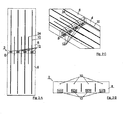
- FIG. 2a shows a plan view of a section on a built-in inventive connecting element 2 according to the first embodiment of the invention.
- the insulating body 8 is, as already shown, cuboid and elongated and has a total of four thrust bearings 12, which are provided approximately equally spaced from each other in the connecting element 2. Furthermore, the tension rods 10 and transverse force rods 34 are shown for receiving transverse forces in the plan view.
- FIG. 2b is a frontal view balcony side on a connecting element 2, in which the arrangement of the thrust bearing 12 in the lower region and the arrangement of the tension rods 10 in the upper region of the connecting element 2 can be seen.
- Figure 2c shows a schematic perspective view of the formation of the connecting element, in which in particular the geometry of the transverse force bars 34 is shown, which extend obliquely through the insulating body and thus are guided from an upper portion of the floor slab 6 to a lower portion of the balcony cover 4.
- FIG. 3a shows two Betonierkartuschen invention 20, 22 in an enlarged view.
- a concreting cartridge 20, 22 according to the invention is constructed like a slanted pyramidal stump, all other frustoconical shapes are suitable but also. Rejuvenating structures towards the front have better heat conduction properties because the contact surfaces are smaller.
- the truncated pyramid concreting cartridges 20, 22 are in particular designed so that they have a planar lower bottom 20.1, 22.1 in installation orientation and an obliquely upward upper wall 20.2, 22.2. This geometry causes the concrete to enter without bubbles during pouring and the pressure bearing structure to achieve optimum strength.
- the cartridges 20, 22 have in the illustrated embodiment, an outer height h a of about 55 mm and an inner height of h i of about 40 mm.
- the depth t of a cartridge 20, 22 corresponds to approximately 40 mm, so that the total depth z. T. corresponds approximately to the thickness of the insulating body 8.
- FIG. 3b shows an outer width b a of the cartridge 20 of 100 mm and an inner width b i of 80 mm.
- the insert part 30, 32 is provided, as already described above.
- Figure 3c shows the cartridges 20, 22 in a schematic perspective view.
- FIG. 4a shows a further embodiment of the invention in a cross-sectional view.
- the local connection element 102 serves to connect a balcony 104 to a floor ceiling 106.
- an insulating body 108 is provided, through which at least one tension rod 110 is performed.
- a sliding bearing 128 is formed by two insert parts 130, 132, which, as in the FIGS. 4b and 5 , are formed in two layers.
- the inserts 130, 132 have a sliding layer 134, wherein the inserts 130, 132 are aligned so that the associated sliding layers slide on each other.
- a fiber concrete layer 136 is provided which effects the effects described in the previous embodiment.
- both inserts 130, 132 may also be connected to each other for easier installation via narrow webs, wherein the webs are formed so that it already breaks at low relative movements to each other.
- the insert parts 130, 132 are inserted into the recess 118 of the sliding bearing before casting the covers 104, 106.
- the two insert parts are already placed in the recess during the production of the connection element, so that no subsequent insertion is required.
Landscapes
- Engineering & Computer Science (AREA)
- Architecture (AREA)
- Physics & Mathematics (AREA)
- Electromagnetism (AREA)
- Civil Engineering (AREA)
- Structural Engineering (AREA)
- Joining Of Building Structures In Genera (AREA)
- Sliding-Contact Bearings (AREA)
Abstract
Description
Die vorliegende Erfindung betrifft ein Anschlusselement, das insbesondere zum Anschluss eines Balkons an eine Geschossdecke (Kragplattenanschlusselement) dient, aber auch für sonstige, thermisch voneinander zu trennende Betonteile, Stahlbetonteile etc., bei denen über die Dämmfuge Querkräfte und Momente übertragen werden, einsetzbar ist. Das Kragplatten-Anschlusselement hat einen Isolierkörper und ein Drucklager, welches wenigstens ein Gleitlager aufweist. Die Erfindung betrifft weiterhin ein Einsatzteil und eine Kartusche für ein derartiges Anschlusselement.The present invention relates to a connection element which serves in particular for connecting a balcony to a floor slab (cantilever connection element), but also for other, thermally separated concrete parts, reinforced concrete parts, etc., in which transverse forces and moments are transmitted via the Dämmfuge, can be used. The cantilever connection element has an insulating body and a thrust bearing, which has at least one sliding bearing. The invention further relates to an insert part and a cartridge for such a connection element.
Anschlusselemente der vorgenannten Art sind seit vielen Jahren bekannt. Ein bekanntes Kragplattenanschlusselement ist in der
Nachteilig dabei ist, dass die Integration der Druckelemente in die Wärmedämmplatten Probleme bereitet. Der Isolierkörper besteht üblicherweise aus Leichtmaterialien, zum Beispiel Polystyrolschaum, welcher durch seine geringe Festigkeit kaum die Integration von großen und schweren Druckelementen zulässt.The disadvantage here is that the integration of the printing elements in the thermal insulation panels causes problems. The insulating body is usually made of light materials, for example polystyrene foam, which hardly allows the integration of large and heavy pressure elements due to its low strength.
Weiterhin ist aus der
Ein ähnliches Kragplattenanschlusselement ist auch aus der
Problematisch bei den vorgenannten Kragplattenanschlusselementen ist weiterhin, dass der Beton, welcher zur Ausbildung des Drucklagers in dafür vorgesehene Ausnehmungen entweder des Isolierkörpers oder gemäß dem letztgenannten Stand der Technik dafür vorgesehenen Hülsen eingefüllt wird, zu ungleichmäßigem Austrocknen und zur Rissbildung und/oder zur Blasenbildung neigt. Dies reduziert die Belastbarkeit und die Haltbarkeit des Drucklagers, sodass dieses größer dimensioniert werden muss. Aus Isolationsgründen besteht jedoch immer das Bestreben, das Drucklager möglichst klein auszubilden, da dieses schlechtere Isolationseigenschaften als der Isolationskörper selbst aufweist. Insbesondere die Verwendung von Metallhülsen hat sich als problematisch herausgestellt, da Metallhülsen Wärme besonders gut leiten und dadurch die lsolationseigenschaften verschlechtern.A problem with the aforementioned cantilever panel connection elements is further that the concrete, which is filled to form the thrust bearing in recesses provided for either the insulator or provided according to the latter prior art sleeves, tends to uneven drying and cracking and / or blistering. This reduces the load capacity and durability of the thrust bearing, so it must be sized larger. For reasons of isolation, however, there is always the desire to design the thrust bearing as small as possible, since this has poorer insulation properties than the insulating body itself. In particular, the use of metal sleeves has proven to be problematic because metal sleeves conduct heat particularly well and thereby deteriorate the insulation properties.
Aufgabe der Erfindung ist somit, ein Anschlusselement, ein Einsatzteil und eine Kartusche der vorgenannten Art anzugeben, welche die Nachteile aus dem Stand der Technik überwinden und ein kompakt dimensionierbares Drucklager, das dennoch sehr gute Festigkeiten aufweist und sehr langlebig ist, herzustellen.The object of the invention is thus to provide a connection element, an insert and a cartridge of the aforementioned type, which the disadvantages of the prior overcome the technology and a compact dimensionable thrust bearing, which nevertheless has very good strength and is very durable to produce.
Die Aufgabe der Erfindung wird gelöst durch ein Anschlusselement gemäß den Ansprüchen 1 und 4, ein Einsatzteil gemäß den Ansprüchen 21 und 22 sowie durch eine Kartusche für ein Drucklager gemäß dem Anspruch 27.The object of the invention is achieved by a connecting element according to
Die Erfindung basiert auf der überraschenden Erkenntnis, dass sich die Eigenschaften von Beton durch die Verwendung von bestimmten Materialien, die mit dem Beton eine bevorzugt stoffschlüssige Verbindung eingehen, beeinflussen lassen. Orthotrope Materialien, also solche Materialien, die in unterschiedlichen Richtungen unterschiedliche Elastizitätseigenschaften aufweisen, führen, wenn sie mit Beton vergossen sind, zu einer Ertüchtigung des Betons und zur Erhöhung der Druckbelastbarkeit, da der Beton gleichsam an den orthotropen Materialien fixiert wird und nicht mehr unter bereits geringer Druckbelastung rissig wird und bricht.The invention is based on the surprising finding that the properties of concrete can be influenced by the use of certain materials which enter into a preferably cohesive connection with the concrete. Orthotropic materials, ie those materials which have different elasticity properties in different directions, when cast with concrete, lead to a strengthening of the concrete and to increase the compressive strength, since the concrete is as it were fixed to the orthotropic materials and not under already low pressure load is cracked and breaks.
Derartige Materialien führen bei Verbindung mit dem Beton dazu, dass einerseits die Querdehnung des Betons behindert wird und gleichzeitig Spannungsspitzen durch ungleichmäßige Lastenverteilung reduziert werden.Such materials, when bonded to concrete, on the one hand impede the transverse expansion of the concrete and at the same time reduce stress peaks due to uneven load distribution.
Auch solche Materialien, die bezogen auf die Druckkraftrichtung eine höhere Querdehnfestigkeit als der verwendete Beton aufweisen, führen, wenn sie mit dem Beton eine stoffschlüssige Verbindung eingehen, dazu, dass der Beton hinsichtlich seiner Querdehnung gehemmt ist und dadurch erst viel später Kräfte und Querdehnungen erreicht werden, bei denen der Beton reist.Even those materials which have a higher Querdehnfestigkeit than the concrete used in relation to the compression force, when they enter into a material connection with the concrete, to the fact that the concrete is inhibited in terms of transverse strain and thus much later forces and transverse strains can be achieved in which the concrete travels.
Ein erfindungsgemäßes Anschlusselement, welches insbesondere zum Anschluss einer Kragplatte an eine Geschossdecke vorgesehen ist, weist einen Isolierkörper und ein Drucklager, welches wenigstens ein Gleitlager aufweist, auf. Erfindungsgemäß ist vorgesehen, dass zwischen Druckelement und Gleitlager ein Einsatzteil mit orthotropen Materialeigenschaften vorgesehen ist. Dies ermöglicht, das stark belastete Druckelement lokal zu ertüchtigen, da das Einsatzteil, welches orthotrope Eigenschaften aufweist, zu einer lokalen Ertüchtigung des Druckelements führt.An inventive connecting element, which is provided in particular for connecting a cantilever to a floor slab, has an insulating body and a thrust bearing, which has at least one sliding bearing on. According to the invention it is provided that between the pressure element and sliding bearing Insert with orthotropic material properties is provided. This makes it possible to locally strengthen the heavily loaded printing element, since the insert part, which has orthotropic properties, leads to a local upgrading of the printing element.
Eine vorteilhafte Weiterbildung des Anschlusselements sieht vor, dass das Einsatzteil bezogen auf die Druckkraftrichtung eine höhere Querdehnfestigkeit als der verwendete Beton aufweist. Mit Querdehnfestigkeit ist das Verhalten des Materials unter Druckkraft senkrecht zur Druckkraftrichtung zu verstehen, das die Ausdehnung in Querrichtung in Abhängigkeit von der einwirkenden Druckkraft angibt. Wenn das Einsatzteil hier eine höhere Querdehnfestigkeit aufweist als der verwendete Beton und Beton und Einsatzteil miteinander eine stoffschlüssige Verbindung eingehen, so wird in einem an das Einsatzteil angrenzenden Bereich des Betons durch die höhere Querdehnfestigkeit des Einsatzteils dieser an einem stärkeren Ausdehnen gehindert, der Beton wird gleichsam umschnürt. Dadurch wird die Belastbarkeit und Dauerhaltbarkeit des Drucklagers entschieden erhöht.An advantageous development of the connection element provides that the insert has a higher Querdehnfestigkeit relative to the compression force direction than the concrete used. Transverse tensile strength is to be understood as meaning the behavior of the material under compressive force perpendicular to the compression force direction, which indicates the extent in the transverse direction as a function of the applied compressive force. If the insert part here has a higher Querdehnfestigkeit than the concrete used and concrete and insert enter into a cohesive connection with each other, then in a region adjacent to the insert portion of the concrete is prevented by the higher Querdehnfestigkeit the insert part of a greater expansion, the concrete is as it were umschnürt. As a result, the resilience and durability of the thrust bearing is decidedly increased.
Weiterhin besonders vorteilhaft ist es, wenn das Einsatzteil in Druckkraftrichtung eine höhere Elastizität als der verwendete Beton aufweist, also wenn bei Einwirkung einer gegebenen Kraft das Einsatzteil stärker nachgibt als der Beton. Damit lassen sich Druckspitzen besonders gut abbauen und die Belastung des Drucklagers wird gleichmäßiger, was die Haltbarkeit des Anschlusselements weiter erhöht. Besonders vorteilhaft ist somit eine Materialwahl für das Einsatzteil dergestalt, dass gleichzeitig eine höhere Querdehnfestigkeit als auch eine höhere Elastizität in Druckkraftrichtung erreicht wird.It is furthermore particularly advantageous if the insert part has a greater elasticity in the pressure force direction than the concrete used, that is to say when the input part yields more when exposed to a given force than the concrete. This pressure peaks can be reduced particularly well and the load of the thrust bearing is uniform, which further increases the durability of the connection element. Thus, a material choice for the insert part is particularly advantageous in that at the same time a higher Querdehnfestigkeit and a higher elasticity is achieved in the pressure direction.
Besonders vorteilhaft ist es, wenn das Einsatzteil in Druckkraftrichtung eine höhere Elastizität als der verwendete Beton aufweist, da dadurch Spannungsspitzen abgebaut werden können.It is particularly advantageous if the insert part has a higher elasticity in the pressure force direction than the concrete used, as this can break down stress peaks.
Dabei kann mit besonderem Vorteil vorgesehen werden, dass das Einsatzteil orthotrope Materialeigenschaften aufweist.It can be provided with particular advantage that the insert has orthotropic material properties.
Die folgenden Weiterbildungen der Erfindung beziehen sich auf die beiden voran beschriebenen nebeneinanderstehenden Alternativen des Anschlusselements.The following developments of the invention relate to the two above-described alternatives of the connecting element described above.
Ein weiterer Vorteil ergibt sich für die beiden vorgenannten Anschlusselemente, wenn das Einsatzteil als Druckelement ausgebildet ist. Das Einsatzteil ist, verglichen mit dem Volumen der miteinander zu verbindenden Betonbauteile, relativ klein, sodass ohne erhebliche Mehrkosten auf besonders hochwertige Einsatzteile zurückgegriffen werden kann. Beim Gießen der Betonbauteile, also beispielsweise der Kragplatte oder der Geschossdecke, geht dann das Einsatzteil eine stoffschlüssige Verbindung mit dem frisch gegossenen Beton ein, wird also an die Platten angegossen.Another advantage results for the two aforementioned connection elements, when the insert is designed as a pressure element. The insert is, compared to the volume of concrete components to be joined, relatively small, so that can be used without significant additional costs on particularly high-quality inserts. When casting the concrete components, so for example the cantilever or the floor ceiling, then the insert is a material connection with the freshly poured concrete, so it is cast on the plates.
Nach einer alternativen Ausgestaltung wird das Druckelement beim Herstellen der Betonbauteile durch Gießen der Betonbauteile selbst aus dem gleichen Material in einem einzigen Arbeitsschritt hergestellt.According to an alternative embodiment, the pressure element is produced in the manufacture of concrete components by casting the concrete components themselves from the same material in a single step.
Bevorzugt ist dabei vorgesehen, dass das Druckelement aus Beton oder aus Leichtbeton gegossen ist. Die Druckelemente lassen sich dann beim Gießen von Geschossdecke und Kragplatte, beispielsweise Balkon, mit einformen. Dies stellt eine optimale Verbindung von Geschossdecke und Druckelement bzw. Kragplatte und Druckelement sicher und hat den weiteren Vorteil, dass das Drucklager und das Einsatzteil eine stoffschlüssige Verbindung eingehen, was die ertüchtigenden Eigenschaften des Einsatzteils weiter erhöht.It is preferably provided that the pressure element is cast from concrete or lightweight concrete. The printing elements can then be molded in the casting of floor slab and cantilever, for example balcony. This ensures an optimal connection of floor slab and pressure element or cantilever and pressure element and has the further advantage that the thrust bearing and the insert enter into a cohesive connection, which further increases the inherent properties of the insert.
Nach einer alternativen Ausgestaltung kann das Druckelement auch vorgeformt sein und aus Holz oder einem Verbundwerkstoff bestehen. Auch vorgeformte Beton- oder Leichtbeton-Druckelemente sind denkbar. Separat einsetzbare Druckelemente weisen den Vorteil auf, dass sie hinsichtlich ihrer Eigenschaften optimal auf den Einsatzzweck angepasst werden können. Holz und Verbundwerkstoffe haben gegenüber Beton den weiteren Vorteil einer schlechteren Wärmeleitfähigkeit, sodass die Wärmeabgabe von der Geschossdecke an die Kragplatte weiter reduziert werden kann.According to an alternative embodiment, the pressure element may also be preformed and made of wood or a composite material. Preformed concrete or lightweight concrete pressure elements are conceivable. Separately usable printing elements have the advantage that they can be optimally adapted to the intended use in terms of their properties. Wood and composites have the further advantage of a worse than concrete Thermal conductivity, so that the heat output from the floor ceiling can be further reduced to the cantilever.
Das Einsatzteil ist gemäß einer weiteren vorteilhaften Ausgestaltung im Wesentlichen aus einem Faserverbundwerkstoff mit gerichteten Fasern hergestellt. Die Ausrichtung der Fasern ist an die spezifischen Anforderungen des Drucklagers angepasst. Dazu sind bevorzugt die Fasern des Einsatzteils im Wesentlichen parallel zur Oberfläche des Gleitlagers ausgerichtet. Dadurch lässt sich zum Beispiel beim Einsatz von Betondrucklagern eine Umschnürung des Betons erreichen, welche verhindert, dass der Beton bei Druckbelastung seitlich nachgibt, wodurch Einrisse entstehen können.The insert is made according to a further advantageous embodiment substantially of a fiber composite material with directed fibers. The orientation of the fibers is adapted to the specific requirements of the thrust bearing. For this purpose, the fibers of the insert part are preferably aligned substantially parallel to the surface of the sliding bearing. As a result, for example, when using concrete pressure bearings, a constriction of the concrete can be achieved, which prevents the concrete from yielding laterally under pressure, as a result of which tears may occur.
Eine besonders vorteilhafte Ausgestaltung des Einsatzteils sieht vor, dieses aus Faserbeton herzustellen. Faserbeton ist einerseits günstig, hat bessere Wärmedämmeigenschaften als normaler Beton und ist in der Lage, Druckspitzen im Bereich des Druckelements abzubauen. Darüber hinaus hat Faserbeton eine Oberflächenbeschaffenheit, die eine gute stoffschlüssige Verbindung zwischen dem Druckelement und dem Einsatzteil beim Gießen von Geschossdecke und Kragplatte sicherstellt.A particularly advantageous embodiment of the insert provides to produce this fiber-reinforced concrete. Fiber concrete is on the one hand favorable, has better thermal insulation properties than normal concrete and is able to reduce pressure peaks in the region of the pressure element. In addition, fiber concrete has a surface texture that ensures a good cohesive connection between the pressure element and the insert during the casting of floor slab and cantilever.
Nach einer weiteren vorteilhaften Ausgestaltung sind das oder die Drucklager in wenigstens einer Ausnehmung des Isolierkörpers ausgebildet. Die Ausnehmungen lassen sich an geeigneten, zuvor berechneten Stellen in den Isolierkörper einbringen, wodurch Anzahl und Dimensionierung der Drucklager optimiert wird.According to a further advantageous embodiment, the one or more thrust bearings are formed in at least one recess of the insulating body. The recesses can be introduced at suitable, previously calculated points in the insulating body, whereby number and dimensioning of the thrust bearing is optimized.
Eine weitere, besonders vorteilhafte Ausgestaltung sieht vor, dass wenigstens eine Kartusche verwendet wird, die im Gebrauchszustand in der oder den Ausnehmungen.eingesetzt ist. Pro Ausnehmung können auch mehr als eine Kartusche, beispielsweise zwei aneinanderliegende Kartuschen kragplatten- und geschossdeckenseitig vorgesehen sein. Eine derartige Kartusche führt einerseits dazu, dass zum Beispiel bei der Verwendung von Beton zur Ausbildung des Druckstücks dieser blasenfrei und gleichmäßig durchtrocknet, wodurch die Stabilität und die Haltbarkeit des Drucklagers erhöht wird. Ein weiterer Vorteil ist, dass verhindert wird, dass Beton in den Isolierkörper eindringt, wodurch dieser seine lsoliereigenschaften teilweise verliert.A further, particularly advantageous embodiment provides that at least one cartridge is used, which is used in the use or in the recesses. Per recess more than one cartridge, for example, two adjacent cartridges can be provided kragplatten- and storey ceiling side. On the one hand, such a cartridge means that, for example, when concrete is used to form the pressure piece, it dries free of bubbles and uniformly, as a result of which Stability and durability of the thrust bearing is increased. Another advantage is that it prevents concrete from entering the insulator, thereby partially losing its insulative properties.
Vorteilhafterweise ist die Kartusche wannenartig ausgebildet und der Wannenboden bildet eine Gleitfläche des Gleitlagers. Damit kann die Kartusche einerseits das Drucklager mantelseitig vollständig umgeben und andererseits gleichzeitig als Gleitlager dienen. Wannenartig bedeutet im erfindungsgemäßen Sinne, dass die Kartusche räumliche Gestalt hat und an einer Seite offen gestaltet ist, sodass das Drucklager in die im Übrigen geschlossene Kartusche hineinragen kann.Advantageously, the cartridge is formed trough-like and the trough bottom forms a sliding surface of the sliding bearing. Thus, the cartridge on the one hand completely surround the thrust bearing shell side and on the other hand also serve as a sliding bearing. Trough-like in the sense of the invention means that the cartridge has a spatial shape and is designed to be open on one side, so that the pressure bearing can protrude into the otherwise closed cartridge.
Besonders vorteilhaft ist weiterhin, wenn das Einsatzteil in der Kartusche angeordnet ist. Dabei kann in jeder der Kartuschen ein Einsatzteil angeordnet sein oder nur in einigen der Kartuschen. Die Anordnung des Einsatzteils in der Kartusche vereinfacht die Verwendung des Anschlusselements in besonderer Weise, das Einsatzteil zum Beispiel lose in der Kartusche befestigbar ist, sodass zum Herstellen der Kragplatte lediglich das Anschlusselement in die richtige Lage gebracht werden muss und dann, wie üblich z. B. Geschossdecke und Kragplatte gegossen werden können.It is furthermore particularly advantageous if the insert part is arranged in the cartridge. In this case, an insert may be arranged in each of the cartridges or only in some of the cartridges. The arrangement of the insert part in the cartridge simplifies the use of the connection element in a special way, the insert part, for example, loosely mounted in the cartridge, so that for producing the cantilever plate only the connection element must be brought into the correct position and then, as usual z. B. floor slab and cantilever can be poured.
Als besonders geeignete Geometrien für die Kartusche haben sich kegelstumpfartige, insbesondere kreiskegelstumpfartige oder pyramidenstumpfartige Geometrien erwiesen. Besonders vorteilhaft dabei ist, wenn die Geometrie nicht rotationssymmetrisch ist. Insbesondere kann der untere Bereich der Kartusche in einer Montageausrichtung im Wesentlichen horizontal ausgerichtet sein, was es erlaubt, das Druckelement möglichst weit unten in einem Querschnitt anzuordnen, wodurch eine optimierte Momententragfähigkeit des Druckelementes erreicht werden kann.Particularly suitable geometries for the cartridge are truncated cone-like, in particular circular truncated cones or truncated pyramid-like geometries. It is particularly advantageous in this case if the geometry is not rotationally symmetrical. In particular, the lower region of the cartridge can be oriented substantially horizontally in a mounting orientation, which makes it possible to arrange the pressure element as far as possible in a cross section, whereby an optimized torque carrying capacity of the pressure element can be achieved.
Als besondere geeignete Materialien zur Herstellung der Kartusche haben sich Kunststoffe, insbesondere POM, PP, PA oder PE erwiesen oder sonstige Kunststoffe, welche gute Gleiteigenschaften aufweisen. Damit lassen sich einerseits eine sehr gute Funktion des Gleitlagers sicherstellen und andererseits gute Trocknungseigenschaften des Betons, sodass dieser nicht zu Rissbildungen neigt.Plastics, in particular POM, PP, PA or PE, have proved to be particular suitable materials for producing the cartridge Plastics which have good sliding properties. This ensures on the one hand a very good function of the sliding bearing and on the other hand good drying properties of the concrete, so that it does not tend to cracking.
Alternativ zu einer Kartusche kann vorgesehen sein, dass in die Ausnehmung des Isolierkörpers direkt eine Beschichtung eingebracht ist, insbesondere eingesprüht. Dies reduziert die Herstellungskosten des Anschlusselements und gewährleistet im Wesentlichen die gleiche Funktion, die eine Kartusche aufweist.Alternatively to a cartridge can be provided that in the recess of the insulating directly a coating is introduced, in particular sprayed. This reduces the manufacturing cost of the terminal member and provides substantially the same function as a cartridge.
Ein unabhängiger Gedanke der Erfindung sieht ein Einsatzteil für ein Drucklager eines Anschlusselements vor, das im Wesentlichen aus einem Material mit orthotropen Eigenschaften besteht. Ein derartiges Einsatzteil weist die bereits zuvor aufgeführten Vorteile auf, nämlich Ertüchtigung des Betons durch Umschnürung und durch Abbau von Druckspitzen und Verbesserung der lsolationseigenschaften des Drucklagers.An independent aspect of the invention provides an insert member for a thrust bearing of a connector substantially consisting of a material having orthotropic properties. Such an insert part has the advantages already mentioned above, namely the concrete is reinforced by lashing and by reducing pressure peaks and improving the insulation properties of the thrust bearing.
Eine alternative Ausgestaltung gemäß dem zweiten unabhängigen Gedanken der Erfindung sieht ein Einsatzteil für ein Drucklager eines Anschlusselementes vor, das im Wesentlichen aus einem Material mit einer, bezogen auf die Druckkraftrichtung des Drucklagers, höheren Querdehnfestigkeit als das verwendete Material des Anschlusselementes besteht.An alternative embodiment according to the second independent idea of the invention provides an insert for a thrust bearing of a connection element, which consists essentially of a material with respect to the pressure force direction of the thrust bearing, higher Querdehnfestigkeit than the material used of the connection element.
Als besonders geeignetes Material für das Einsatzteil hat sich Fasermaterial mit gerichteten Fasern erwiesen. Die Fasern sind dabei senkrecht zu einer Auflagefläche des Drucklagers ausgerichtet.As a particularly suitable material for the insert fiber material has proved with directed fibers. The fibers are aligned perpendicular to a bearing surface of the thrust bearing.
Als geeignete Materialien haben sich im Wesentlichen Faserbeton, Holz, Leichtbeton und/oder Faserverbundmaterial erwiesen, die allesamt orthotrope Eigenschaften aufweisen und gute Wärmeisolationseigenschaften.Fiber-reinforced concrete, wood, lightweight concrete and / or fiber composite material have proven to be suitable materials, all of which have orthotropic properties and good heat-insulating properties.
Nach einer weiteren vorteilhaften Ausgestaltung ist vorgesehen, dass an dem Einsatzteil eine Schicht oder ein Abschnitt aus einem Gleitmaterial vorgesehen ist. Dann kann das Einsatzteil gleichzeitig als Gleitlager eingesetzt werden. Separate Gleitlager müssen dann für das Druckelement nicht mehr vorgesehen werden.According to a further advantageous embodiment, it is provided that a layer or a portion of a sliding material is provided on the insert part. Then the insert can be used simultaneously as a plain bearing. Separate plain bearings then no longer have to be provided for the pressure element.
Als besonders geeignete Materialien für das Gleitmaterial haben sich POM, PP und/oder PE herausgestellt, die allesamt gute Gleiteigenschaften aufweisen.Particularly suitable materials for the sliding material POM, PP and / or PE have been found, all of which have good sliding properties.
Ein letzter unabhängiger Gedanke der Erfindung betrifft eine Kartusche für ein Drucklager eines Anschlusselements, welche aus einem Kunststoff, insbesondere POM, PP, PA oder PE mit guten Gleiteigenschaften besteht.
Vorteilhafterweise ist die Kartusche wannenartig ausgebildet und der Wannenboden bildet eine Gleitfläche des Gleitlagers. Damit kann die Kartusche einerseits das Drucklager mantelseitig vollständig umgeben und andererseits gleichzeitig als Gleitlager dienen. Wannenartig bedeutet im erfindungsgemäßen Sinne, dass die Kartusche räumliche Gestalt hat und an einer Seite offen gestaltet ist, sodass das Drucklager in die im Übrigen geschlossene Kartusche hineinragen kann.A final independent idea of the invention relates to a cartridge for a thrust bearing of a connection element, which consists of a plastic, in particular POM, PP, PA or PE with good sliding properties.
Advantageously, the cartridge is formed trough-like and the trough bottom forms a sliding surface of the sliding bearing. Thus, the cartridge on the one hand completely surround the thrust bearing shell side and on the other hand also serve as a sliding bearing. Trough-like in the sense of the invention means that the cartridge has a spatial shape and is designed to be open on one side, so that the pressure bearing can protrude into the otherwise closed cartridge.
Besonders vorteilhaft ist weiterhin, wenn das Einsatzteil in der Kartusche angeordnet ist. Dabei kann in jeder der Kartuschen ein Einsatzteil angeordnet sein oder nur in einigen der Kartuschen. Die Anordnung des Einsatzteils in der Kartusche vereinfacht die Verwendung des Anschlusselements in besonderer Weise, das Einsatzteil zum Beispiel lose in der Kartusche befestigbar ist, sodass zum Herstellen der Kragplatte lediglich das Anschlusselement in die richtige Lage gebracht werden muss und dann, wie üblich z. B. Geschossdecke und Kragplatte gegossen werden können.It is furthermore particularly advantageous if the insert part is arranged in the cartridge. In this case, an insert may be arranged in each of the cartridges or only in some of the cartridges. The arrangement of the insert part in the cartridge simplifies the use of the connection element in a special way, the insert part, for example, loosely mounted in the cartridge, so that for producing the cantilever plate only the connection element must be brought into the correct position and then, as usual z. B. floor slab and cantilever can be poured.
Als besonders geeignete Geometrien für die Kartusche haben sich kegelstumpfartige, insbesondere kreiskegelstumpfartige oder pyramidenstumpfartige Geometrien erwiesen. Besonders vorteilhaft dabei ist, wenn die Geometrie nicht rotationssymmetrisch ist. Insbesondere kann der untere Bereich der Kartusche in einer Montageausrichtung im Wesentlichen horizontal ausgerichtet sein, was es erlaubt, das Druckelement möglichst weit unten in einem Querschnitt anzuordnen, wodurch eine optimale Druckeinleitung erreicht werden kann.Particularly suitable geometries for the cartridge are truncated cone-like, in particular circular truncated cones or truncated pyramid-like geometries. It is particularly advantageous in this case if the geometry is not rotationally symmetrical. In particular, the lower Be aligned portion of the cartridge in a mounting orientation substantially horizontally, which allows the pressure element as far as possible to arrange in a cross section, whereby an optimal pressure introduction can be achieved.
Als besondere geeignete Materialien zur Herstellung der Kartusche haben sich Kunststoffe, insbesondere POM, PP, PA oder PE erwiesen oder sonstige Kunststoffe, welche gute Gleiteigenschaften aufweisen. Damit lassen sich einerseits eine sehr gute Funktion des Gleitlagers sicherstellen und andererseits gute Trocknungseigenschaften des Betons, sodass dieser nicht zu Rissbildungen neigt.Plastics, in particular POM, PP, PA or PE have proven as special suitable materials for the production of the cartridge or other plastics, which have good sliding properties. This ensures on the one hand a very good function of the sliding bearing and on the other hand good drying properties of the concrete, so that it does not tend to cracking.
Bevorzugt wird die Kartusche durch Sprühen, Spritzen oder Tauchen hergestellt. Auf diese Weise lassen sich die notwendigen wannenartigen Strukturen besonders kostengünstig herstellen.Preferably, the cartridge is made by spraying, spraying or dipping. In this way, the necessary trough-like structures can be produced particularly inexpensively.
Weitere Ziele, Vorteile, Merkmale und Anwendungsmöglichkeiten der vorliegenden Erfindung ergeben sich aus der nachfolgenden Beschreibung eines Ausführungsbeispieles anhand der Zeichnung. Dabei bilden alle beschriebenen und/oder bildlich dargestellten Merkmale für sich oder in beliebiger sinnvoller Kombination den Gegenstand der vorliegenden Erfindung, auch unabhängig von ihrer Zusammenfassung in den Ansprüchen oder deren Rückbeziehung.Other objects, advantages, features and applications of the present invention will become apparent from the following description of an embodiment with reference to the drawings. All described and / or illustrated features alone or in any meaningful combination form the subject matter of the present invention, also independent of their summary in the claims or their dependency.
Es zeigen:
- Figur 1 a
- einen Querschnitt durch eine erste Ausführungsform eines erfindungsgemäßen Anschlusselements;
- Figur 1b
- eine Vergrößerung eines Ausschnitts aus
Figur 1 a; - Figur 2a
- eine Draufsicht auf ein erfindungsgemäßes Anschlusselement;
- Figur 2b
- eine Frontalansicht auf ein erfindungsgemäßes Anschlusselement;
- Figur 2c
- eine schematische perspektivische Ansicht auf das erfindungsgemäße Anschlusselement;
- Figur 3a
- zwei erfindungsgemäße Kartuschen in einer Querschnittsdarstellung;
- Figur 3b
- eine Frontalansicht auf eine erfindungsgemäße Kartusche;
- Figur 3c
- eine perspektivische Ansicht zweier erfindungsgemäßer Kartuschen.
- Figur 4a
- einen schematischen Querschnitt durch ein erfindungsgemäßes Kragplattenelement gemäß einer zweiten Ausführungsform;
- Figur 4b
- eine Vergrößerung eines Ausschnitts aus
Figur 2a ; - Figur 5
- ein erfindungsgemäßes Einsatzteil;
- FIG. 1 a
- a cross section through a first embodiment of a connecting element according to the invention;
- FIG. 1b
- an enlargement of a section
FIG. 1 a; - FIG. 2a
- a plan view of an inventive connecting element;
- FIG. 2b
- a front view of an inventive connecting element;
- Figure 2c
- a schematic perspective view of the connecting element according to the invention;
- FIG. 3a
- two cartridges according to the invention in a cross-sectional view;
- FIG. 3b
- a front view of a cartridge according to the invention;
- Figure 3c
- a perspective view of two inventive cartridges.
- FIG. 4a
- a schematic cross section through an inventive Kragplattenelement according to a second embodiment;
- FIG. 4b
- an enlargement of a section
FIG. 2a ; - FIG. 5
- an insert according to the invention;
Das Anschlusselement 2 weist zunächst einen Isolierkörper 8 auf, welcher sich quaderförmig und langgestreckt senkrecht zur dargestellten Schnittebene zwischen Balkon 4 und Geschossdecke 6 erstreckt. Das Anschlusselement 2 weist im oberen Bereich einen Zugstab 10 auf, der durch die Schwerkraft auftretende Zugkräfte der Balkonplatte 4 aufnimmt und in die Geschossdecke 6 einleitet. Zur Aufnahme von Druckkräften ist im unteren Bereich des Isolierkörpers 8 ein Drucklager 12 vorgesehen, welches in
Das Drucklager 12 weist zwei sich aneinander abstützende Druckelemente, ein balkonseitiges Druckelement 14 und ein geschossdeckenseitiges Druckelement 16 auf, die an Balkon- 4 bzw. Geschossdecke 6 angeformt oder beim Gießen der Balkonplatte 4 bzw. der Geschossdecke 6 mit ausgegossen werden. Alternativ können auch vorgefertigte Druckelemente, z. B. aus Holz oder einem Verbundwerkstoff hergestellt werden.The pressure bearing 12 has two mutually supporting pressure elements, a balcony-
Zur Aufnahme des Drucklagers 12 ist in dem Isolierkörper 8 eine Ausnehmung 18 vorgesehen, die das Drucklager 12 aufnimmt. In die Ausnehmung 18 sind zwei Kartuschen, eine balkonseitige Kartusche 20 und eine geschossdeckenseitige Kartusche 22, eingesetzt, die jeweils wannenförmig ausgestaltet sind. Die Geometrie der Kartuschen 20, 22 ist in den
Die Kartusche 20, 22 bestehen gemäß der ersten Ausführungsform der Erfindung aus einem Material mit guten Gleiteigenschaften, insbesondere aus POM (Polyacetal), und bilden dadurch ein Gleitlager 28. Auch andere Materialien mit einem niedrigen Haftreibungskoeffizienten bzw. mit guten Gleiteigenschaften aufeinander sind einsetzbar, so zum Beispiel PTFE (Teflon), PP, PE, PA und dergleichen.The
Das Gleitlager 28 dient zur Aufnahme von Relativbewegungen zwischen Balkon 4 und Geschossdecke 6, wie sie beispielsweise bei Belastung des Balkons und insbesondere bei unterschiedlichen oder schwankenden Temperaturen zwischen Balkon 4 und Geschossdecke 6 entstehen. Im Winter nimmt die Balkonplatte 4 in etwa die Außentemperatur an, während die Geschossdecke 6 durch die Heizung des Innenraums des betreffenden Gebäudes meist Temperaturen zwischen 18 und 24° Celius aufweist. Im Sommer hingegen kann sich das Verhältnis umdrehen und die Balkondecke 4 eine höhere Temperatur annehmen als die Geschossdecke 6.The sliding
Die wärmeausdehnungsbedingten Relativverschiebungen zwischen Balkon 4 und Geschossdecke 6 führen zu Verschiebungen der balkonseitigen Kartusche 20 und der geschossseitigen Kartusche 22 gegeneinander, welche durch das Gleitlager 28, welches durch die Wannenböden 24, 26 gebildet ist, aufgenommen werden.The heat expansion-related relative displacements between the
Im Innenbereich der wannenförmigen Kartuschen 20, 22 sind jeweils Einsatzteile 30, 32 vorgesehen, welche in dem dargestellten Ausführungsbeispiel aus Faserbeton mit gerichteten Fasern besteht. Ein derartiger Faserbeton mit gerichteten Fasern hat orthotrope Eigenschaften, das heißt unterschiedliche Elastizitätskoeffizienten in unterschiedliche Richtungen und ist vor dem Gießen von Balkon 4 und Geschossdecke 6 in die jeweilige Kartusche 20, 22 in den Wannenboden 24, 26 eingelegt.In the inner region of the trough-shaped
Beim Vergießen der Decken 4, 6 mit flüssigem Beton gehen die Einsatzteile 30, 32 eine Verbindung mit dem Beton ein, welcher in den Innenraum der Kartuschen 20, 22 einfließt. Dadurch wird der Beton in diesem Bereich ertüchtigt, das heißt, er kann höhere Druckkräfte aufnehmen, da er nicht wie normaler Beton seitlich ausreißen kann. Die Fasern sind im Wesentlichen senkrecht zur Richtung der Druckkraft ausgerichtet, also im Wesentlichen parallel zum Wannenboden 24, 26 und parallel zur Gleitfläche des Gleitlagers 28.When pouring the
Die Ertüchtigung des Betons basiert darauf, dass die durch Druck entstehende Querdehnung an der Oberfläche des Betons reduziert wird, da durch die stoffschlüssige Verbindung von Beton und von Einsatzteil 30, 32 der Beton umschnürt wird und dadurch höhere Druckkräfte aufnehmen und übertragen kann.The upgrading of the concrete is based on the fact that the pressure-induced transverse strain is reduced at the surface of the concrete, since the concrete connection of concrete and insert 30, 32 of the concrete is wrapped and thus can absorb and transmit higher pressure forces.
Im Resultat kann das Drucklager 12 kleiner dimensioniert werden, was die Isolationseigenschaften des Anschlusselements 2 verbessert und Wärmeverluste mindert.As a result, the
Ein weiterer Vorteil des Faserbetoneinsatzteils 30, 32 ist, dass es zusätzliche Isolationseigenschaften aufweist und damit die Wärmeleitung zwischen Balkondecke 4 und Geschossdecke 6 reduziert.Another advantage of the fiber
Ein zusätzlicher Vorteil der bevorzugt hochfesten Faserbetoneinsatzteile 30, 32 ist, dass entgegen der Wirkung bei einem Elastomerlager nicht durch die Querdehnung des Materials selbst zusätzliche Querkräfte auf die Betondrucklager übertragen werden, welche ein vorzeitiges Versagen der Drucklager begünstigen würde.An additional advantage of the preferably high strength fiber reinforced concrete inserts 30, 32 is that, contrary to the effect of an elastomeric bearing, additional transverse forces are not transmitted to the concrete thrust bearings by the transverse strain of the material itself, which would promote premature failure of the thrust bearings.
In
Die pyramidenstumpfartigen Betonierkartuschen 20, 22 sind insbesondere so gestaltet, dass sie in Einbauausrichtung einen ebenen unteren Boden 20.1, 22.1 aufweisen und eine schräg nach oben hin verlaufende obere Wandung 20.2, 22.2. Diese Geometrie bewirkt, dass der Beton beim Eingießen blasenfrei einläuft und die Drucklagerstruktur eine optimale Festigkeit erreicht. Die Kartuschen 20, 22 weisen im dargestellten Ausführungsbeispiel eine äußere Höhe ha von etwa 55 mm und eine innere Höhe von hi von etwa 40 mm. Die Tiefe t einer Kartusche 20, 22 entspricht in etwa 40 mm, sodass die Gesamttiefe z. T. in etwa der Dicke des Isolierkörpers 8 entspricht.The truncated
Die Frontalansicht nach
Im Gegensatz zur zuerst dargestellten Ausführungsform gemäß der
Ein Gleitlager 128 wird durch zwei Einsatzteile 130, 132 gebildet, welche, wie in den
In einer vorteilhaften nicht dargestellten Ausführungsform können beide Einsatzteile 130, 132 auch zur einfacheren Montage über schmale Stege miteinander verbunden sein, wobei die Stege so ausgebildet sind, dass diese bereits bei geringen Relativbewegungen zueinander bricht. Die Einsatzteile 130, 132 werden vor dem Gießen der Decken 104, 106 in die Ausnehmung 118 des Gleitlagers eingesetzt.In an advantageous embodiment, not shown, both
Alternativ werden die beiden Einsatzteile bereits bei der Herstellung des Anschlusselements so in der Ausnehmung platziert, dass kein nachträgliches Einsetzen erforderlich ist.Alternatively, the two insert parts are already placed in the recess during the production of the connection element, so that no subsequent insertion is required.
Bezugszeichenliste
- 2
- Anschlusselement
- 4
- Balkon
- 6
- Geschossdecke
- 8
- Isolierkörper
- 10
- Zugstab
- 12
- Drucklager
- 14
- balkonseitiges Druckelement
- 16
- geschossdeckenseitiges Druckelement
- 18
- Ausnehmung
- 20
- balkonseitige Kartusche
- 20.1
- unterer Boden
- 22.1
- obere Wandung
- 22
- geschossdeckenseitige Kartusche
- 24, 26
- Wannenboden
- 28
- Gleitlager
- 30, 32
- Einsatzteil
- 34
- Querkraftstäbe
- 102
- Anschlusselement
- 104
- Balkon
- 106
- Geschossdecke
- 108
- Isolierkörper
- 110
- Zugstab
- 112
- Drucklager
- 118
- Ausnehmung
- 128
- Gleitlager
- 130, 132
- Einsatzteil
- 134
- Gleitschicht
- 136
- Faserbetonschicht
- 2
- connecting element
- 4
- balcony
- 6
- floor ceiling
- 8th
- insulator
- 10
- tension rod
- 12
- thrust bearing
- 14
- balcony-side pressure element
- 16
- storey-ceiling-side pressure element
- 18
- recess
- 20
- balcony-side cartridge
- 20.1
- lower ground
- 22.1
- upper wall
- 22
- floor-level cartouche
- 24, 26
- Wannenboden
- 28
- bearings
- 30, 32
- insert
- 34
- Shear bars
- 102
- connecting element
- 104
- balcony
- 106
- floor ceiling
- 108
- insulator
- 110
- tension rod
- 112
- thrust bearing
- 118
- recess
- 128
- bearings
- 130, 132
- insert
- 134
- Overlay
- 136
- Fiber concrete layer
Claims (15)
Applications Claiming Priority (1)
| Application Number | Priority Date | Filing Date | Title |
|---|---|---|---|
| DE200710056508 DE102007056508B4 (en) | 2007-11-22 | 2007-11-22 | Connection element, insert and cartridge |
Publications (2)
| Publication Number | Publication Date |
|---|---|
| EP2063033A2 true EP2063033A2 (en) | 2009-05-27 |
| EP2063033A3 EP2063033A3 (en) | 2010-02-10 |
Family
ID=40278998
Family Applications (1)
| Application Number | Title | Priority Date | Filing Date |
|---|---|---|---|
| EP08020139A Withdrawn EP2063033A3 (en) | 2007-11-22 | 2008-11-19 | Connection element, insert and cartridge |
Country Status (2)
| Country | Link |
|---|---|
| EP (1) | EP2063033A3 (en) |
| DE (1) | DE102007056508B4 (en) |
Cited By (1)
| Publication number | Priority date | Publication date | Assignee | Title |
|---|---|---|---|---|
| DE102012103776A1 (en) * | 2012-04-27 | 2013-10-31 | Rainer Eger | Thrust bearing, component and method of manufacturing the device |
Citations (3)
| Publication number | Priority date | Publication date | Assignee | Title |
|---|---|---|---|---|
| DE3005571B1 (en) | 1980-02-14 | 1981-06-04 | Eberhard 7570 Baden-Baden Schöck | Component for heat insulation in buildings |
| DE3116381A1 (en) | 1981-04-24 | 1982-11-11 | Eberhard 7570 Baden-Baden Schöck | Heat-insulating element for buildings with cantilevered wall parts |
| EP1229176A2 (en) | 2001-01-18 | 2002-08-07 | Pecon AG | Cantilever plate element |
Family Cites Families (6)
| Publication number | Priority date | Publication date | Assignee | Title |
|---|---|---|---|---|
| DE2849864C2 (en) * | 1978-11-17 | 1982-08-05 | Schorn, Harald, Prof. Dr.-Ing., 5100 Aachen | Multi-layer bearing with elastic deformation properties |
| DE3244472A1 (en) * | 1982-12-01 | 1984-06-14 | Eberhard Ing. Schöck (grad.), 7570 Baden-Baden | PRINTING ELEMENT IN A PRE-HEAT INSULATING COMPONENT FOR PROTECTIVE BUILDING PARTS |
| DE3302719C1 (en) * | 1983-01-27 | 1984-08-23 | Eberhard Ing. Schöck (grad.), 7570 Baden-Baden | Component for heat insulation in buildings |
| CH695021A5 (en) * | 2001-01-18 | 2005-11-15 | Pecon Ag C O Hto Treuhand Ag | Bonding tie between a cantilever slab and a concrete ceiling slab has a pressure unit between them, with a cube insulating body and passage openings for the reinforcement rods |
| DE10102931A1 (en) * | 2001-01-23 | 2002-07-25 | Schoeck Entwicklungsgmbh | Component for thermal insulation |
| US20050244550A1 (en) * | 2004-03-18 | 2005-11-03 | Suzanne Penfold | Disposable condiment tray holder and method |
-
2007
- 2007-11-22 DE DE200710056508 patent/DE102007056508B4/en not_active Expired - Fee Related
-
2008
- 2008-11-19 EP EP08020139A patent/EP2063033A3/en not_active Withdrawn
Patent Citations (3)
| Publication number | Priority date | Publication date | Assignee | Title |
|---|---|---|---|---|
| DE3005571B1 (en) | 1980-02-14 | 1981-06-04 | Eberhard 7570 Baden-Baden Schöck | Component for heat insulation in buildings |
| DE3116381A1 (en) | 1981-04-24 | 1982-11-11 | Eberhard 7570 Baden-Baden Schöck | Heat-insulating element for buildings with cantilevered wall parts |
| EP1229176A2 (en) | 2001-01-18 | 2002-08-07 | Pecon AG | Cantilever plate element |
Cited By (1)
| Publication number | Priority date | Publication date | Assignee | Title |
|---|---|---|---|---|
| DE102012103776A1 (en) * | 2012-04-27 | 2013-10-31 | Rainer Eger | Thrust bearing, component and method of manufacturing the device |
Also Published As
| Publication number | Publication date |
|---|---|
| DE102007056508B4 (en) | 2010-11-25 |
| EP2063033A3 (en) | 2010-02-10 |
| DE102007056508A1 (en) | 2009-06-04 |
Similar Documents
| Publication | Publication Date | Title |
|---|---|---|
| EP2455556B1 (en) | Insulating connection element for transferring compression | |
| EP2943624B1 (en) | Thermally insulating console for joining a façade to a building wall | |
| EP3690159B1 (en) | Building section and method for thermal decoupling of concreted sections of buildings | |
| EP3953602B1 (en) | Bending spring element comprising a fibre reinforced material | |
| EP2646627A1 (en) | Device for connecting reinforced concrete slabs to a wall construction or ceiling construction made of reinforced concrete | |
| DE19711813C2 (en) | Thermally insulating component | |
| EP3296476B1 (en) | Assembly for connecting a building wall with a floor or ceiling plate and form block for such an assembly | |
| EP1745182B1 (en) | Cantilever plate connection element | |
| EP1892344A1 (en) | Thermally insulating construction element | |
| DE202013006229U1 (en) | Thermally insulating component | |
| EP3467222B1 (en) | Moulded building block to be fitted between a building wall and a floor or ceiling panel, and section of a building with such a moulded building block | |
| EP1482101A1 (en) | Wall element, method for the production of wall elements and connecting means for a wall element | |
| DE102007056508B4 (en) | Connection element, insert and cartridge | |
| WO2008113347A2 (en) | Constructional element for thermal insulation | |
| EP3225758A1 (en) | Connection component for thermal isolation between a vertical and horizontal building part | |
| EP3467221B1 (en) | Moulded building block to be fitted between a building wall and a floor or ceiling panel, and section of a building with such a moulded building block | |
| EP3788210B1 (en) | Shear dowel | |
| EP3663474B1 (en) | Device for decoupling heat between a concrete wall of a building and a floor and production method | |
| EP3225759B1 (en) | Connection component for thermal isolation between vertically connected building sections | |
| EP1229176A2 (en) | Cantilever plate element | |
| EP3835501B1 (en) | Arrangement for connecting a structural part with a frontal exterior part | |
| EP3912778B1 (en) | Supporting vertical precast concrete part and method for the horizontal production of a supporting vertical precast concrete part | |
| WO2008113348A2 (en) | Constructional element for thermal insulation | |
| AT523024B1 (en) | Building construction and method of forming same | |
| EP3467220B1 (en) | Building section and method for producing same |
Legal Events
| Date | Code | Title | Description |
|---|---|---|---|
| PUAI | Public reference made under article 153(3) epc to a published international application that has entered the european phase |
Free format text: ORIGINAL CODE: 0009012 |
|
| AK | Designated contracting states |
Kind code of ref document: A2 Designated state(s): AT BE BG CH CY CZ DE DK EE ES FI FR GB GR HR HU IE IS IT LI LT LU LV MC MT NL NO PL PT RO SE SI SK TR |
|
| AX | Request for extension of the european patent |
Extension state: AL BA MK RS |
|
| PUAL | Search report despatched |
Free format text: ORIGINAL CODE: 0009013 |
|
| AK | Designated contracting states |
Kind code of ref document: A3 Designated state(s): AT BE BG CH CY CZ DE DK EE ES FI FR GB GR HR HU IE IS IT LI LT LU LV MC MT NL NO PL PT RO SE SI SK TR |
|
| AX | Request for extension of the european patent |
Extension state: AL BA MK RS |
|
| 17P | Request for examination filed |
Effective date: 20100706 |
|
| AKX | Designation fees paid |
Designated state(s): AT BE BG CH CY CZ DE DK EE ES FI FR GB GR HR HU IE IS IT LI LT LU LV MC MT NL NO PL PT RO SE SI SK TR |
|
| 17Q | First examination report despatched |
Effective date: 20110913 |
|
| GRAP | Despatch of communication of intention to grant a patent |
Free format text: ORIGINAL CODE: EPIDOSNIGR1 |
|
| INTG | Intention to grant announced |
Effective date: 20160628 |
|
| STAA | Information on the status of an ep patent application or granted ep patent |
Free format text: STATUS: THE APPLICATION IS DEEMED TO BE WITHDRAWN |
|
| 18D | Application deemed to be withdrawn |
Effective date: 20161109 |