EP2063033A2 - Elément de raccordement, pièce d'insertion et cartouche - Google Patents
Elément de raccordement, pièce d'insertion et cartouche Download PDFInfo
- Publication number
- EP2063033A2 EP2063033A2 EP08020139A EP08020139A EP2063033A2 EP 2063033 A2 EP2063033 A2 EP 2063033A2 EP 08020139 A EP08020139 A EP 08020139A EP 08020139 A EP08020139 A EP 08020139A EP 2063033 A2 EP2063033 A2 EP 2063033A2
- Authority
- EP
- European Patent Office
- Prior art keywords
- concrete
- cartridge
- insert
- connecting element
- sliding
- Prior art date
- Legal status (The legal status is an assumption and is not a legal conclusion. Google has not performed a legal analysis and makes no representation as to the accuracy of the status listed.)
- Withdrawn
Links
- 239000004567 concrete Substances 0.000 claims abstract description 74
- 239000000463 material Substances 0.000 claims abstract description 35
- 239000002131 composite material Substances 0.000 claims abstract description 8
- 239000002023 wood Substances 0.000 claims abstract description 6
- 239000002657 fibrous material Substances 0.000 claims abstract description 3
- 239000000835 fiber Substances 0.000 claims description 23
- 239000004033 plastic Substances 0.000 claims description 7
- 229920003023 plastic Polymers 0.000 claims description 7
- 230000006835 compression Effects 0.000 claims description 4
- 238000007906 compression Methods 0.000 claims description 4
- 229920006324 polyoxymethylene Polymers 0.000 abstract description 7
- 239000011210 fiber-reinforced concrete Substances 0.000 abstract description 4
- -1 polyoxymethylene Polymers 0.000 abstract 3
- 229930040373 Paraformaldehyde Natural products 0.000 abstract 1
- 239000004952 Polyamide Substances 0.000 abstract 1
- 239000004698 Polyethylene Substances 0.000 abstract 1
- 239000004743 Polypropylene Substances 0.000 abstract 1
- 229920002647 polyamide Polymers 0.000 abstract 1
- 229920000573 polyethylene Polymers 0.000 abstract 1
- 229920001155 polypropylene Polymers 0.000 abstract 1
- 229920002994 synthetic fiber Polymers 0.000 abstract 1
- 238000009413 insulation Methods 0.000 description 9
- 238000005266 casting Methods 0.000 description 6
- 238000007639 printing Methods 0.000 description 6
- 239000012212 insulator Substances 0.000 description 4
- 239000010410 layer Substances 0.000 description 4
- 238000004519 manufacturing process Methods 0.000 description 4
- 238000005336 cracking Methods 0.000 description 3
- 238000001035 drying Methods 0.000 description 3
- 230000000694 effects Effects 0.000 description 3
- 238000009434 installation Methods 0.000 description 3
- 239000002184 metal Substances 0.000 description 3
- 239000012791 sliding layer Substances 0.000 description 3
- 238000011161 development Methods 0.000 description 2
- 230000018109 developmental process Effects 0.000 description 2
- 239000011810 insulating material Substances 0.000 description 2
- 230000010354 integration Effects 0.000 description 2
- 230000003014 reinforcing effect Effects 0.000 description 2
- 238000005507 spraying Methods 0.000 description 2
- 229930182556 Polyacetal Natural products 0.000 description 1
- 229910000831 Steel Inorganic materials 0.000 description 1
- 239000004809 Teflon Substances 0.000 description 1
- 229920006362 Teflon® Polymers 0.000 description 1
- 230000015572 biosynthetic process Effects 0.000 description 1
- 239000011248 coating agent Substances 0.000 description 1
- 238000000576 coating method Methods 0.000 description 1
- 238000010276 construction Methods 0.000 description 1
- 238000007598 dipping method Methods 0.000 description 1
- 238000006073 displacement reaction Methods 0.000 description 1
- 238000009826 distribution Methods 0.000 description 1
- 238000005516 engineering process Methods 0.000 description 1
- 230000002349 favourable effect Effects 0.000 description 1
- 230000005484 gravity Effects 0.000 description 1
- 238000010438 heat treatment Methods 0.000 description 1
- 238000003780 insertion Methods 0.000 description 1
- 230000037431 insertion Effects 0.000 description 1
- 238000002955 isolation Methods 0.000 description 1
- 239000007788 liquid Substances 0.000 description 1
- ORQBXQOJMQIAOY-UHFFFAOYSA-N nobelium Chemical compound [No] ORQBXQOJMQIAOY-UHFFFAOYSA-N 0.000 description 1
- 229920006327 polystyrene foam Polymers 0.000 description 1
- 229920001343 polytetrafluoroethylene Polymers 0.000 description 1
- 239000004810 polytetrafluoroethylene Substances 0.000 description 1
- 229920002635 polyurethane Polymers 0.000 description 1
- 239000004814 polyurethane Substances 0.000 description 1
- 230000002028 premature Effects 0.000 description 1
- 239000011150 reinforced concrete Substances 0.000 description 1
- 230000003716 rejuvenation Effects 0.000 description 1
- 230000003068 static effect Effects 0.000 description 1
- 239000010959 steel Substances 0.000 description 1
- 238000005728 strengthening Methods 0.000 description 1
Images



Classifications
-
- E—FIXED CONSTRUCTIONS
- E04—BUILDING
- E04B—GENERAL BUILDING CONSTRUCTIONS; WALLS, e.g. PARTITIONS; ROOFS; FLOORS; CEILINGS; INSULATION OR OTHER PROTECTION OF BUILDINGS
- E04B1/00—Constructions in general; Structures which are not restricted either to walls, e.g. partitions, or floors or ceilings or roofs
- E04B1/003—Balconies; Decks
- E04B1/0038—Anchoring devices specially adapted therefor with means for preventing cold bridging
Definitions
- the present invention relates to a connection element which serves in particular for connecting a balcony to a floor slab (cantilever connection element), but also for other, thermally separated concrete parts, reinforced concrete parts, etc., in which transverse forces and moments are transmitted via the Dämmfuge, can be used.
- the cantilever connection element has an insulating body and a thrust bearing, which has at least one sliding bearing.
- the invention further relates to an insert part and a cartridge for such a connection element.
- connection elements of the aforementioned type have been known for many years.
- a well-known cantilever connection element is in the DE 30 05 571 disclosed.
- the cantilever panel connection element there has an elongated cuboid insulating body made of thermally insulating material, which is provided with elongated, metal reinforcing elements which extend essentially transversely to the insulating body and project laterally.
- the component has pressure elements that are integrated in the insulating body and have the cross section of the insulating corresponding dimensions.
- the pressure elements are steel construction components which are introduced into the insulating body.
- the disadvantage here is that the integration of the printing elements in the thermal insulation panels causes problems.
- the insulating body is usually made of light materials, for example polystyrene foam, which hardly allows the integration of large and heavy pressure elements due to its low strength.
- thermal insulation element for buildings with projecting wall parts which consists of an elongated insulating body of thermally insulating material having transverse and laterally projecting reinforcing elements and at least one integrated pressure element.
- the insulating body has recesses which are filled during installation with concrete and form the two aligned pressure elements, which are separated by a sliding bearing.
- the local cantilever plate connection element provides for the use of two cup-shaped sleeves in the through holes formed in the insulating body, the closed base surfaces lie on one another, wherein at least one sliding layer of a sliding bearing is formed between the two base surfaces.
- a problem with the aforementioned cantilever panel connection elements is further that the concrete, which is filled to form the thrust bearing in recesses provided for either the insulator or provided according to the latter prior art sleeves, tends to uneven drying and cracking and / or blistering. This reduces the load capacity and durability of the thrust bearing, so it must be sized larger.
- the thrust bearing For reasons of isolation, however, there is always the desire to design the thrust bearing as small as possible, since this has poorer insulation properties than the insulating body itself.
- the use of metal sleeves has proven to be problematic because metal sleeves conduct heat particularly well and thereby deteriorate the insulation properties.
- the object of the invention is thus to provide a connection element, an insert and a cartridge of the aforementioned type, which the disadvantages of the prior overcome the technology and a compact dimensionable thrust bearing, which nevertheless has very good strength and is very durable to produce.
- the object of the invention is achieved by a connecting element according to claims 1 and 4, an insert according to claims 21 and 22 and by a cartridge for a thrust bearing according to claim 27.
- the invention is based on the surprising finding that the properties of concrete can be influenced by the use of certain materials which enter into a preferably cohesive connection with the concrete.
- Orthotropic materials ie those materials which have different elasticity properties in different directions, when cast with concrete, lead to a strengthening of the concrete and to increase the compressive strength, since the concrete is as it were fixed to the orthotropic materials and not under already low pressure load is cracked and breaks.
- An inventive connecting element which is provided in particular for connecting a cantilever to a floor slab, has an insulating body and a thrust bearing, which has at least one sliding bearing on. According to the invention it is provided that between the pressure element and sliding bearing Insert with orthotropic material properties is provided. This makes it possible to locally strengthen the heavily loaded printing element, since the insert part, which has orthotropic properties, leads to a local upgrading of the printing element.
- connection element provides that the insert has a higher Querdehnfestmaschine relative to the compression force direction than the concrete used.
- Transverse tensile strength is to be understood as meaning the behavior of the material under compressive force perpendicular to the compression force direction, which indicates the extent in the transverse direction as a function of the applied compressive force. If the insert part here has a higher Querdehnfestmaschine than the concrete used and concrete and insert enter into a cohesive connection with each other, then in a region adjacent to the insert portion of the concrete is prevented by the higher Querdehnfestmaschine the insert part of a greater expansion, the concrete is as it were umschnürt. As a result, the resilience and durability of the thrust bearing is decidedly increased.
- the insert part has a greater elasticity in the pressure force direction than the concrete used, that is to say when the input part yields more when exposed to a given force than the concrete.
- This pressure peaks can be reduced particularly well and the load of the thrust bearing is uniform, which further increases the durability of the connection element.
- a material choice for the insert part is particularly advantageous in that at the same time a higher Querdehnfestmaschine and a higher elasticity is achieved in the pressure direction.
- the insert part has a higher elasticity in the pressure force direction than the concrete used, as this can break down stress peaks.
- the insert has orthotropic material properties.
- connection elements when the insert is designed as a pressure element.
- the insert is, compared to the volume of concrete components to be joined, relatively small, so that can be used without significant additional costs on particularly high-quality inserts.
- the insert is a material connection with the freshly poured concrete, so it is cast on the plates.
- the pressure element is produced in the manufacture of concrete components by casting the concrete components themselves from the same material in a single step.
- the pressure element is cast from concrete or lightweight concrete.
- the printing elements can then be molded in the casting of floor slab and cantilever, for example balcony. This ensures an optimal connection of floor slab and pressure element or cantilever and pressure element and has the further advantage that the thrust bearing and the insert enter into a cohesive connection, which further increases the inherent properties of the insert.
- the pressure element may also be preformed and made of wood or a composite material.
- Preformed concrete or lightweight concrete pressure elements are conceivable.
- Separately usable printing elements have the advantage that they can be optimally adapted to the intended use in terms of their properties.
- Wood and composites have the further advantage of a worse than concrete Thermal conductivity, so that the heat output from the floor ceiling can be further reduced to the cantilever.
- the insert is made according to a further advantageous embodiment substantially of a fiber composite material with directed fibers.
- the orientation of the fibers is adapted to the specific requirements of the thrust bearing.
- the fibers of the insert part are preferably aligned substantially parallel to the surface of the sliding bearing.
- a particularly advantageous embodiment of the insert provides to produce this fiber-reinforced concrete.
- Fiber concrete is on the one hand favorable, has better thermal insulation properties than normal concrete and is able to reduce pressure peaks in the region of the pressure element.
- fiber concrete has a surface texture that ensures a good cohesive connection between the pressure element and the insert during the casting of floor slab and cantilever.
- the one or more thrust bearings are formed in at least one recess of the insulating body.
- the recesses can be introduced at suitable, previously calculated points in the insulating body, whereby number and dimensioning of the thrust bearing is optimized.
- a further, particularly advantageous embodiment provides that at least one cartridge is used, which is used in the use or in the recesses.
- Per recess more than one cartridge for example, two adjacent cartridges can be provided kragplatten- and storey ceiling side.
- such a cartridge means that, for example, when concrete is used to form the pressure piece, it dries free of bubbles and uniformly, as a result of which Stability and durability of the thrust bearing is increased.
- Another advantage is that it prevents concrete from entering the insulator, thereby partially losing its insulative properties.
- the cartridge is formed trough-like and the trough bottom forms a sliding surface of the sliding bearing.
- the cartridge on the one hand completely surround the thrust bearing shell side and on the other hand also serve as a sliding bearing.
- Trough-like in the sense of the invention means that the cartridge has a spatial shape and is designed to be open on one side, so that the pressure bearing can protrude into the otherwise closed cartridge.
- the insert part is arranged in the cartridge.
- an insert may be arranged in each of the cartridges or only in some of the cartridges.
- the arrangement of the insert part in the cartridge simplifies the use of the connection element in a special way, the insert part, for example, loosely mounted in the cartridge, so that for producing the cantilever plate only the connection element must be brought into the correct position and then, as usual z.
- B. floor slab and cantilever can be poured.
- Particularly suitable geometries for the cartridge are truncated cone-like, in particular circular truncated cones or truncated pyramid-like geometries. It is particularly advantageous in this case if the geometry is not rotationally symmetrical.
- the lower region of the cartridge can be oriented substantially horizontally in a mounting orientation, which makes it possible to arrange the pressure element as far as possible in a cross section, whereby an optimized torque carrying capacity of the pressure element can be achieved.
- Plastics in particular POM, PP, PA or PE, have proved to be particular suitable materials for producing the cartridge Plastics which have good sliding properties. This ensures on the one hand a very good function of the sliding bearing and on the other hand good drying properties of the concrete, so that it does not tend to cracking.
- a coating is introduced, in particular sprayed. This reduces the manufacturing cost of the terminal member and provides substantially the same function as a cartridge.
- An independent aspect of the invention provides an insert member for a thrust bearing of a connector substantially consisting of a material having orthotropic properties.
- Such an insert part has the advantages already mentioned above, namely the concrete is reinforced by lashing and by reducing pressure peaks and improving the insulation properties of the thrust bearing.
- An alternative embodiment according to the second independent idea of the invention provides an insert for a thrust bearing of a connection element, which consists essentially of a material with respect to the pressure force direction of the thrust bearing, higher Querdehnfestmaschine than the material used of the connection element.
- the insert fiber material As a particularly suitable material for the insert fiber material has proved with directed fibers.
- the fibers are aligned perpendicular to a bearing surface of the thrust bearing.
- Fiber-reinforced concrete, wood, lightweight concrete and / or fiber composite material have proven to be suitable materials, all of which have orthotropic properties and good heat-insulating properties.
- a layer or a portion of a sliding material is provided on the insert part. Then the insert can be used simultaneously as a plain bearing. Separate plain bearings then no longer have to be provided for the pressure element.
- a final independent idea of the invention relates to a cartridge for a thrust bearing of a connection element, which consists of a plastic, in particular POM, PP, PA or PE with good sliding properties.
- the cartridge is formed trough-like and the trough bottom forms a sliding surface of the sliding bearing.
- the cartridge on the one hand completely surround the thrust bearing shell side and on the other hand also serve as a sliding bearing.
- Trough-like in the sense of the invention means that the cartridge has a spatial shape and is designed to be open on one side, so that the pressure bearing can protrude into the otherwise closed cartridge.
- the insert part is arranged in the cartridge.
- an insert may be arranged in each of the cartridges or only in some of the cartridges.
- the arrangement of the insert part in the cartridge simplifies the use of the connection element in a special way, the insert part, for example, loosely mounted in the cartridge, so that for producing the cantilever plate only the connection element must be brought into the correct position and then, as usual z.
- B. floor slab and cantilever can be poured.
- Particularly suitable geometries for the cartridge are truncated cone-like, in particular circular truncated cones or truncated pyramid-like geometries. It is particularly advantageous in this case if the geometry is not rotationally symmetrical.
- the lower Be aligned portion of the cartridge in a mounting orientation substantially horizontally, which allows the pressure element as far as possible to arrange in a cross section, whereby an optimal pressure introduction can be achieved.
- Plastics in particular POM, PP, PA or PE have proven as special suitable materials for the production of the cartridge or other plastics, which have good sliding properties. This ensures on the one hand a very good function of the sliding bearing and on the other hand good drying properties of the concrete, so that it does not tend to cracking.
- the cartridge is made by spraying, spraying or dipping.
- the necessary trough-like structures can be produced particularly inexpensively.
- FIG. 1a shows a cross section through an inventive connecting element 2, which serves to connect a balcony 4 (cantilever) to a floor ceiling 6.
- the connecting element 2 initially has an insulating body 8, which extends parallelepiped-shaped and elongated perpendicular to the illustrated sectional plane between the balcony 4 and the floor ceiling 6.
- the connecting element 2 has in the upper area a tension rod 10, which absorbs tensile forces of the balcony slab 4 occurring due to gravity and introduces into the floor slab 6.
- a thrust bearing 12 is provided in the lower region of the insulating body 8, which in FIG. 1b is shown in an enlarged section.
- the pressure bearing 12 has two mutually supporting pressure elements, a balcony-side pressure element 14 and a projectile ceiling-side pressure element 16, which are formed on balcony 4 or floor 6 or poured during the casting of the balcony slab 4 and the floor slab 6 with.
- prefabricated printing elements for. B. made of wood or a composite material.
- a recess 18 is provided in the insulating body 8, which receives the thrust bearing 12.
- two cartridges a balcony-side cartridge 20 and a basement-side cartridge 22, are used, which are each designed trough-shaped.
- the geometry of the cartridges 20, 22 is in the FIGS. 3a and 3b explained in more detail.
- the cartridges 20, 22 are aligned so that the tub bottoms 24, 26 abut each other.
- the cartridge 20, 22 according to the first embodiment of the invention of a material with good sliding properties, in particular POM (polyacetal), and thereby form a plain bearing 28.
- POM polyacetal
- other materials with a low coefficient of static friction or with good sliding properties on each other are used, so for example, PTFE (Teflon), PP, PE, PA and the like.
- the sliding bearing 28 serves to accommodate relative movements between the balcony 4 and floor 6, as they arise, for example, when the balcony and especially at varying or fluctuating temperatures between the balcony 4 and floor 6.
- the balcony plate 4 takes in about the outside temperature, while the floor ceiling 6 by the heating of the interior of the building in question usually has temperatures between 18 and 24 ° Celius.
- the ratio can turn around and the balcony ceiling 4 assume a higher temperature than the floor ceiling. 6
- each insert parts 30, 32 are provided, which consists in the illustrated embodiment of fiber concrete with directed fibers.
- Such a fiber concrete with directional fibers has orthotropic properties, that is, different coefficients of elasticity in different directions and is inserted into the respective tub 20, 22 in the tub bottom 24, 26 before pouring the balcony 4 and floor slab 6.
- the upgrading of the concrete is based on the fact that the pressure-induced transverse strain is reduced at the surface of the concrete, since the concrete connection of concrete and insert 30, 32 of the concrete is wrapped and thus can absorb and transmit higher pressure forces.
- the thrust bearing 12 can be made smaller, which improves the insulation properties of the connection element 2 and reduces heat losses.
- fiber concrete insert 30, 32 Another advantage of the fiber concrete insert 30, 32 is that it has additional insulation properties and thus reduces the heat conduction between the balcony ceiling 4 and floor 6.
- An additional advantage of the preferably high strength fiber reinforced concrete inserts 30, 32 is that, contrary to the effect of an elastomeric bearing, additional transverse forces are not transmitted to the concrete thrust bearings by the transverse strain of the material itself, which would promote premature failure of the thrust bearings.
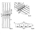
- FIG. 2a shows a plan view of a section on a built-in inventive connecting element 2 according to the first embodiment of the invention.
- the insulating body 8 is, as already shown, cuboid and elongated and has a total of four thrust bearings 12, which are provided approximately equally spaced from each other in the connecting element 2. Furthermore, the tension rods 10 and transverse force rods 34 are shown for receiving transverse forces in the plan view.
- FIG. 2b is a frontal view balcony side on a connecting element 2, in which the arrangement of the thrust bearing 12 in the lower region and the arrangement of the tension rods 10 in the upper region of the connecting element 2 can be seen.
- Figure 2c shows a schematic perspective view of the formation of the connecting element, in which in particular the geometry of the transverse force bars 34 is shown, which extend obliquely through the insulating body and thus are guided from an upper portion of the floor slab 6 to a lower portion of the balcony cover 4.
- FIG. 3a shows two Betonierkartuschen invention 20, 22 in an enlarged view.
- a concreting cartridge 20, 22 according to the invention is constructed like a slanted pyramidal stump, all other frustoconical shapes are suitable but also. Rejuvenating structures towards the front have better heat conduction properties because the contact surfaces are smaller.
- the truncated pyramid concreting cartridges 20, 22 are in particular designed so that they have a planar lower bottom 20.1, 22.1 in installation orientation and an obliquely upward upper wall 20.2, 22.2. This geometry causes the concrete to enter without bubbles during pouring and the pressure bearing structure to achieve optimum strength.
- the cartridges 20, 22 have in the illustrated embodiment, an outer height h a of about 55 mm and an inner height of h i of about 40 mm.
- the depth t of a cartridge 20, 22 corresponds to approximately 40 mm, so that the total depth z. T. corresponds approximately to the thickness of the insulating body 8.
- FIG. 3b shows an outer width b a of the cartridge 20 of 100 mm and an inner width b i of 80 mm.
- the insert part 30, 32 is provided, as already described above.
- Figure 3c shows the cartridges 20, 22 in a schematic perspective view.
- FIG. 4a shows a further embodiment of the invention in a cross-sectional view.
- the local connection element 102 serves to connect a balcony 104 to a floor ceiling 106.
- an insulating body 108 is provided, through which at least one tension rod 110 is performed.
- a sliding bearing 128 is formed by two insert parts 130, 132, which, as in the FIGS. 4b and 5 , are formed in two layers.
- the inserts 130, 132 have a sliding layer 134, wherein the inserts 130, 132 are aligned so that the associated sliding layers slide on each other.
- a fiber concrete layer 136 is provided which effects the effects described in the previous embodiment.
- both inserts 130, 132 may also be connected to each other for easier installation via narrow webs, wherein the webs are formed so that it already breaks at low relative movements to each other.
- the insert parts 130, 132 are inserted into the recess 118 of the sliding bearing before casting the covers 104, 106.
- the two insert parts are already placed in the recess during the production of the connection element, so that no subsequent insertion is required.
Landscapes
- Engineering & Computer Science (AREA)
- Architecture (AREA)
- Physics & Mathematics (AREA)
- Electromagnetism (AREA)
- Civil Engineering (AREA)
- Structural Engineering (AREA)
- Joining Of Building Structures In Genera (AREA)
- Sliding-Contact Bearings (AREA)
Applications Claiming Priority (1)
| Application Number | Priority Date | Filing Date | Title |
|---|---|---|---|
| DE200710056508 DE102007056508B4 (de) | 2007-11-22 | 2007-11-22 | Anschlusselement, Einsatzteil sowie Kartusche |
Publications (2)
| Publication Number | Publication Date |
|---|---|
| EP2063033A2 true EP2063033A2 (fr) | 2009-05-27 |
| EP2063033A3 EP2063033A3 (fr) | 2010-02-10 |
Family
ID=40278998
Family Applications (1)
| Application Number | Title | Priority Date | Filing Date |
|---|---|---|---|
| EP08020139A Withdrawn EP2063033A3 (fr) | 2007-11-22 | 2008-11-19 | Elément de raccordement, pièce d'insertion et cartouche |
Country Status (2)
| Country | Link |
|---|---|
| EP (1) | EP2063033A3 (fr) |
| DE (1) | DE102007056508B4 (fr) |
Cited By (1)
| Publication number | Priority date | Publication date | Assignee | Title |
|---|---|---|---|---|
| DE102012103776A1 (de) * | 2012-04-27 | 2013-10-31 | Rainer Eger | Drucklager, Bauelement und Verfahren zur Herstellung des Bauelements |
Citations (3)
| Publication number | Priority date | Publication date | Assignee | Title |
|---|---|---|---|---|
| DE3005571B1 (de) | 1980-02-14 | 1981-06-04 | Eberhard 7570 Baden-Baden Schöck | Bauelement zur Waermedaemmung bei Gebaeuden |
| DE3116381A1 (de) | 1981-04-24 | 1982-11-11 | Eberhard 7570 Baden-Baden Schöck | Waermedaemmelement fuer gebaeude mit vorkragenden wandteilen |
| EP1229176A2 (fr) | 2001-01-18 | 2002-08-07 | Pecon AG | Element de connexion pour dalle en porte-a-faux |
Family Cites Families (6)
| Publication number | Priority date | Publication date | Assignee | Title |
|---|---|---|---|---|
| DE2849864C2 (de) * | 1978-11-17 | 1982-08-05 | Schorn, Harald, Prof. Dr.-Ing., 5100 Aachen | Mehrschichtiges Lager mit elastischen Verformungseigenschaften |
| DE3244472A1 (de) * | 1982-12-01 | 1984-06-14 | Eberhard Ing. Schöck (grad.), 7570 Baden-Baden | Druckelement in einem waermedaemmenden fertigbauteil fuer vorkragende gebaeudeteile |
| DE3302719C1 (de) * | 1983-01-27 | 1984-08-23 | Eberhard Ing. Schöck (grad.), 7570 Baden-Baden | Bauelement zur Waermedaemmung bei Gebaeuden |
| CH695021A5 (de) * | 2001-01-18 | 2005-11-15 | Pecon Ag C O Hto Treuhand Ag | Kragplattenanschlusselement. |
| DE10102931A1 (de) * | 2001-01-23 | 2002-07-25 | Schoeck Entwicklungsgmbh | Bauelement zur Wärmedämmung |
| US20050244550A1 (en) * | 2004-03-18 | 2005-11-03 | Suzanne Penfold | Disposable condiment tray holder and method |
-
2007
- 2007-11-22 DE DE200710056508 patent/DE102007056508B4/de not_active Expired - Fee Related
-
2008
- 2008-11-19 EP EP08020139A patent/EP2063033A3/fr not_active Withdrawn
Patent Citations (3)
| Publication number | Priority date | Publication date | Assignee | Title |
|---|---|---|---|---|
| DE3005571B1 (de) | 1980-02-14 | 1981-06-04 | Eberhard 7570 Baden-Baden Schöck | Bauelement zur Waermedaemmung bei Gebaeuden |
| DE3116381A1 (de) | 1981-04-24 | 1982-11-11 | Eberhard 7570 Baden-Baden Schöck | Waermedaemmelement fuer gebaeude mit vorkragenden wandteilen |
| EP1229176A2 (fr) | 2001-01-18 | 2002-08-07 | Pecon AG | Element de connexion pour dalle en porte-a-faux |
Cited By (1)
| Publication number | Priority date | Publication date | Assignee | Title |
|---|---|---|---|---|
| DE102012103776A1 (de) * | 2012-04-27 | 2013-10-31 | Rainer Eger | Drucklager, Bauelement und Verfahren zur Herstellung des Bauelements |
Also Published As
| Publication number | Publication date |
|---|---|
| DE102007056508B4 (de) | 2010-11-25 |
| EP2063033A3 (fr) | 2010-02-10 |
| DE102007056508A1 (de) | 2009-06-04 |
Similar Documents
| Publication | Publication Date | Title |
|---|---|---|
| EP2455556B1 (fr) | Elément de raccordement isolant transmettant la force de pression | |
| EP2943624B1 (fr) | Console thermiquement isolante destinée à relier une façade à une paroi de bâtiment | |
| EP3690159B1 (fr) | Enveloppe de bâtiment et procédé d'isolement thermique des enveloppes de bâtiment en béton | |
| EP3953602B1 (fr) | Élément de ressort à flexion ayant un material renforcé de fibres | |
| EP2646627A1 (fr) | Dispositif permettant de fixer des dalles en béton armé à un système de plancher ou de cloison en béton armé | |
| DE19711813C2 (de) | Thermisch isolierendes Bauelement | |
| EP3296476B1 (fr) | Dispositif de liaison d'un mur de bâtiment à une dalle de sol ou de plafond et élément de moulage d'un tel système | |
| EP1745182B1 (fr) | Element de connexion de dalle en console | |
| EP1892344A1 (fr) | Elément de construction thermo-isolant | |
| DE202013006229U1 (de) | Thermisch isolierendes Bauteil | |
| EP3467222B1 (fr) | Élément moulé destiné à etre placé entre un mur de construction et une plaque de sol ou de plafond et section de construction pourvue d'un tel élément moulé | |
| EP1482101A1 (fr) | Elément de construction, procédé pour fabriquer des éléments de construction et moyens de liaison pour élément de construction | |
| DE102007056508B4 (de) | Anschlusselement, Einsatzteil sowie Kartusche | |
| WO2008113347A2 (fr) | Élément d'isolation thermique | |
| EP3225758A1 (fr) | Élément de raccordement d'isolement thermique entre un élément de bâtiment vertical et un élément de bâtiment horizontal | |
| EP3467221B1 (fr) | Élément moulé destiné à être placé entre un mur de construction et une plaque de sol ou de plafond, et section de construction pourvus d'un tel élément | |
| EP3788210B1 (fr) | Système d'ancrage à force transversale | |
| EP3663474B1 (fr) | Dispositif d'isolement thermique entre un mur de bâtiment bétonné et un plancher, ainsi que procédé de fabrication | |
| EP3225759B1 (fr) | Élément de raccordement d'isolation thermique d'éléments de bâtiments verticaux reliés | |
| EP1229176A2 (fr) | Element de connexion pour dalle en porte-a-faux | |
| EP3835501B1 (fr) | Arrangement pour connecter une pièce de construction avec une partie extérieure frontale | |
| EP3912778B1 (fr) | Procédé de fabrication à plat d'une pièce porteuse verticale préfabriquée en béton et pièce porteuse verticale préfabriquée en béton | |
| WO2008113348A2 (fr) | Élément d'isolation thermique | |
| AT523024B1 (de) | Gebäudekonstruktion und Verfahren zur Bildung derselben | |
| EP3467220B1 (fr) | Partie de bâtiment et procédé de fabrication d'une telle partie de bâtiment |
Legal Events
| Date | Code | Title | Description |
|---|---|---|---|
| PUAI | Public reference made under article 153(3) epc to a published international application that has entered the european phase |
Free format text: ORIGINAL CODE: 0009012 |
|
| AK | Designated contracting states |
Kind code of ref document: A2 Designated state(s): AT BE BG CH CY CZ DE DK EE ES FI FR GB GR HR HU IE IS IT LI LT LU LV MC MT NL NO PL PT RO SE SI SK TR |
|
| AX | Request for extension of the european patent |
Extension state: AL BA MK RS |
|
| PUAL | Search report despatched |
Free format text: ORIGINAL CODE: 0009013 |
|
| AK | Designated contracting states |
Kind code of ref document: A3 Designated state(s): AT BE BG CH CY CZ DE DK EE ES FI FR GB GR HR HU IE IS IT LI LT LU LV MC MT NL NO PL PT RO SE SI SK TR |
|
| AX | Request for extension of the european patent |
Extension state: AL BA MK RS |
|
| 17P | Request for examination filed |
Effective date: 20100706 |
|
| AKX | Designation fees paid |
Designated state(s): AT BE BG CH CY CZ DE DK EE ES FI FR GB GR HR HU IE IS IT LI LT LU LV MC MT NL NO PL PT RO SE SI SK TR |
|
| 17Q | First examination report despatched |
Effective date: 20110913 |
|
| GRAP | Despatch of communication of intention to grant a patent |
Free format text: ORIGINAL CODE: EPIDOSNIGR1 |
|
| INTG | Intention to grant announced |
Effective date: 20160628 |
|
| STAA | Information on the status of an ep patent application or granted ep patent |
Free format text: STATUS: THE APPLICATION IS DEEMED TO BE WITHDRAWN |
|
| 18D | Application deemed to be withdrawn |
Effective date: 20161109 |