EP2063060A2 - Joint doté d'une baguette d'étanchéité abaissable et d'au moins un élément de déclenchement - Google Patents
Joint doté d'une baguette d'étanchéité abaissable et d'au moins un élément de déclenchement Download PDFInfo
- Publication number
- EP2063060A2 EP2063060A2 EP08020263A EP08020263A EP2063060A2 EP 2063060 A2 EP2063060 A2 EP 2063060A2 EP 08020263 A EP08020263 A EP 08020263A EP 08020263 A EP08020263 A EP 08020263A EP 2063060 A2 EP2063060 A2 EP 2063060A2
- Authority
- EP
- European Patent Office
- Prior art keywords
- seal
- sealing strip
- triggering
- rod
- trigger
- Prior art date
- Legal status (The legal status is an assumption and is not a legal conclusion. Google has not performed a legal analysis and makes no representation as to the accuracy of the status listed.)
- Granted
Links
Images


Classifications
-
- F—MECHANICAL ENGINEERING; LIGHTING; HEATING; WEAPONS; BLASTING
- F16—ENGINEERING ELEMENTS AND UNITS; GENERAL MEASURES FOR PRODUCING AND MAINTAINING EFFECTIVE FUNCTIONING OF MACHINES OR INSTALLATIONS; THERMAL INSULATION IN GENERAL
- F16J—PISTONS; CYLINDERS; SEALINGS
- F16J15/00—Sealings
- F16J15/02—Sealings between relatively-stationary surfaces
- F16J15/06—Sealings between relatively-stationary surfaces with solid packing compressed between sealing surfaces
- F16J15/061—Sealings between relatively-stationary surfaces with solid packing compressed between sealing surfaces with positioning means
-
- E—FIXED CONSTRUCTIONS
- E06—DOORS, WINDOWS, SHUTTERS, OR ROLLER BLINDS IN GENERAL; LADDERS
- E06B—FIXED OR MOVABLE CLOSURES FOR OPENINGS IN BUILDINGS, VEHICLES, FENCES OR LIKE ENCLOSURES IN GENERAL, e.g. DOORS, WINDOWS, BLINDS, GATES
- E06B7/00—Special arrangements or measures in connection with doors or windows
- E06B7/16—Sealing arrangements on wings or parts co-operating with the wings
- E06B7/18—Sealing arrangements on wings or parts co-operating with the wings by means of movable edgings, e.g. draught sealings additionally used for bolting, e.g. by spring force or with operating lever
- E06B7/20—Sealing arrangements on wings or parts co-operating with the wings by means of movable edgings, e.g. draught sealings additionally used for bolting, e.g. by spring force or with operating lever automatically withdrawn when the wing is opened, e.g. by means of magnetic attraction, a pin or an inclined surface, especially for sills
- E06B7/215—Sealing arrangements on wings or parts co-operating with the wings by means of movable edgings, e.g. draught sealings additionally used for bolting, e.g. by spring force or with operating lever automatically withdrawn when the wing is opened, e.g. by means of magnetic attraction, a pin or an inclined surface, especially for sills with sealing strip being moved to a retracted position by elastic means, e.g. springs
Definitions
- the present invention relates to a gasket with a sealing strip which can be lowered when the gasket is triggered, for example for sealing the bottom air of a door, and a mechanism comprising a coupling element, the mechanism being suitable and arranged for triggering the gasket in a movement of the first coupling element Direction parallel to the sealing strip in a perpendicular movement of the sealing strip implement.
- the in the patent with the publication number DD 291 117 A5 disclosed seal has in addition to the trigger on a second element, which can cause the lowering of the seal.
- This second element is a floating bolt rod which is passed through the seal.
- the tie rod is not coupled to the mechanism for lowering the weather strip. Rather, the floating bolt bar engages over a transversely displaceable in the rod and spring loaded bolt directly to the sealing strip to move them in height.
- the sealing strip of the patent DD 291 117 A5 disclosed seal can be completely lowered and rests over the entire length on the floor to seal the soil air, on the one hand the release of the trigger by hitting the frame and on the other hand, a lowering of the drive bolt rod of the door is necessary.
- the trigger causes lowering of the sealing strip at a first end of the seal, while the drive bolt rod causes the lowering at a second end of the seal.
- the in the patent DD 291 117 A5 thus revealed seal has a total of two triggering elements, namely the trigger element, which projects laterally beyond the seal housing, and the floating bolt bar.
- the one element for triggering nor the other element for triggering is suitable for completely bringing the sealing strip into contact with the floor.
- the complete lowering of the sealing strip is known with a laterally protruding from the sealing housing release element, there are no satisfactory solutions with which the complete lowering of the sealing strip by means of a drive or Kantriegelstange is possible.
- the invention has the object of providing a seal of the type mentioned in such a way that the seal is suitable and adapted to cooperate with a triggering element, which in an action direction at an angle greater than 0 °, in particular acts perpendicular to the direction of extension of the sealing strip on the seal.
- the seal is suitable for a cooperation with a triggering element with a direction of movement greater than 0 °, in particular perpendicular to the direction of movement of the coupling element and set up.
- the trigger element may be part of the seal or not belong to the seal and only cooperate with the seal.
- a graspriegelstange or Kantriegelstange acting as a trigger element not directly on the sealing strip, but provided as a trigger elementkulturriegel- or Kantriegelstange cooperates with the mechanism having the coupling element which receives the movement of the trigger element.
- the movement of the trigger element and the coupling element is converted into a lowering movement of the sealing strip over the entire length of the sealing strip, so that the sealing strip over its entire length, d. h completely, comes to rest on the floor.
- the seal may comprise a seal housing in which the mechanism is arranged, and from which protrudes the sealing strip which extends parallel to the housing at least in the lowered state.
- the seal housing may have at least substantially a U-shape in cross-section.
- the sealing housing of a seal may have a recess through which the triggering element is accessible for triggering, through which the coupling element for Trigger is accessible, which is penetrated by the trigger element or which is suitable and arranged for a penetration of a trigger element.
- the seal has a trigger element or not. If no triggering element is part of the seal, the recess is used to ensure that the coupling element is accessible and the triggering element, which is not part of the seal, can pass through this recess in order to make an operative connection with the coupling element. If, in contrast, the triggering element is part of the seal, the triggering element can be accessible to trigger the seal through the recess or else pass through the recess.
- the coupling element of the mechanism of a seal according to the invention via at least one oblique to the direction of movement of the coupling element surface for the introduction of force from the trigger element can be suitable and arranged. While the trigger element has a substantially vertical direction of movement with respect to the extension direction of the sealing strip, the coupling element has a direction of movement which lies substantially parallel to the extension direction of the sealing strip. The movement of the trigger element must therefore be converted into a perpendicular movement of the coupling element, for which purpose an inclined surface of the coupling element is suitable.
- the inclined surface may be provided on the coupling element at a the triggering element facing the end of the coupling element.
- the triggering element prefferably be suitable and arranged via at least one inclined surface for the direction of movement of the triggering element for introducing force into the coupling element.
- the inclined surface of the triggering element is provided at an end facing the coupling element.
- Both the trigger element and the coupling element may have an inclined surface.
- the oblique surface of the one element, d. H. the triggering element or the coupling element may be suitable and arranged for sliding on a surface of the respective other element.
- the inclined surface can advantageously arched in the manner of a cylinder jacket or arched in the manner of a spherical cap, i. be formed spherical to reduce a surface pressure.
- a seal according to the invention may have a guide element in which the trigger element is arranged guided.
- the guide element can be a guide sleeve with an annular cross-section.
- the guide sleeve is advantageously mounted on the outside of the seal housing and can engage around the recess in the seal housing.
- the trigger element can be biased by means of a spring in the direction of a non-triggered position, so that it can return to a discharge from the release force to a starting position.
- the spring may be supported on the one hand on a collar or on a collar of the trigger element and on the other hand on the seal housing.
- a seal according to the invention may, in a particular embodiment, have a locking element which passes through the sealing strip and is displaceable both relative to the sealing housing and to the sealing strip.
- the locking element may be coupled to the trigger element or for coupling with the Trigger element suitable and be set up, depending on whether the trigger element is part of the seal or not.
- the locking element and the sealing strip may be suitable and arranged to be displaced simultaneously, wherein the locking element is displaced by a triggering by the trigger element by a greater distance than the sealing strip.
- the trigger element and the locking element can be firmly connected to each other. The different distances that cover the locking element and the sealing strip, can be specified via a reduction in the mechanism of the seal.
- An inventive arrangement with a seal according to the invention may comprise a rod which extends substantially perpendicular to the sealing strip and is displaceable to trigger the seal.
- the trigger element for triggering the seal can be acted upon by the rod with a triggering force. It is also possible that the trigger element is formed by the rod.
- the rod may be coupled with an end facing away from the seal for coupling with a lock, a drive bolt or channel latch lever or with a door handle or the like.
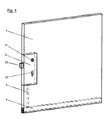
- FIG. 1 shown door leaf 1 has a lock case 2 in a central region.
- the lock case 2 has a receptacle 21 for a door handle, a receptacle 22 for a lock cylinder and a closing latch 23.
- a bottom seal is arranged, which has a sealing strip which can be lowered to seal the so-called ground air.
- the lock case 2 and the bottom seal 4 are connected to each other via a rod 3.
- the bottom seal 4 is designed so that upon movement of the rod 3 down the bottom seal 4 triggers and the sealing strip is lowered to seal the soil air.
- the lowering of the rod 3 can be triggered in different ways. It is conceivable, for example, locking the door by locking or something similar. It is also conceivable that the movement of the rod 3 is coupled to an actuation of the door handle.
- the invention is rather the way in which the rod 3 is coupled to the bottom seal 4 for effecting the lowering of the sealing strip.
- the rod 3 is guided in a channel in the door leaf 1.
- the bottom seal 4 is inserted in a slot on the lower end side of the door panel 1.
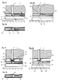
- the bottom seal 4 has a housing 41, which is U-shaped in cross-section. The viewer of the Figures 2 and 2a facing side wall of the seal housing 41 is not shown, as well as the seal housing 41 is cut in a plane parallel to the side walls by connecting the two side walls web.
- a mechanism is housed, of which a coupling element 43 is shown.
- the coupling element 43 is slidably mounted in its direction of extension and parallel to the direction of extension of the sealing strip 42 in the seal housing 41.
- the coupling element 43 causes in a shift in its axial direction from in the FIG. 2 Position shown in the in the FIG. 2a shown position a lowering of the sealing strip 42. Again, this is well known from bottom seals of the prior art.
- the coupling element 43 serves the connection with a trigger, which in the case of the embodiment according to the Figures 2 to 2b is formed by the rod 3.
- the coupling element 43 has an inclined surface 431 on an end facing the rod 3.
- Also serving as a trigger element rod 3 has at its lower end, which faces the coupling element 43, an inclined surface 31st
- a displacement of the trigger element 3 downwards causes the two inclined surfaces 31, 431, in the illustration of FIG. 2 , ie in the raised position of the sealing strip 42, congruent to one another, are shifted against each other to the in the FIG. 2a take positions shown.
- This displacement also causes the lowering of the sealing strip 42, as in the FIG. 2a shown.
- the lower end of the rod 3, that is, the inclined surface 31 of the trigger element can enter into operative connection with the corresponding inclined surface 431 of the coupling element 43, a recess is provided in the web of the seal housing 41, which is penetrated by the trigger element 3.
- FIGS. 3 to 5b schematically illustrated further embodiments correspond in principle in the FIGS. 2 to 2 schematically illustrated embodiment. There are therefore provided the same elements and parts of the arrangements with the same reference numerals. In the following, only the differences between the exemplary embodiments will be discussed.
- the embodiment according to the FIGS. 3 to 3b differs essentially thereby from the embodiment according to the FIGS. 2a to 2b in that a release element 44 separated from the rod 3 is provided, which is in operative connection with the coupling element 43 in order to convert the movement of the rod 3 into a lowering movement of the sealing strip 42.
- the triggering element 44 has a first end which has an inclined surface 441, which is in operative connection with the inclined surface 431 of the coupling element 43.
- the other end of the trigger element 44 forms a contact surface for the rod 3.
- the trigger member 44 is slidably mounted in a guide sleeve 45 which is mounted on top of the web of the seal housing 41. The sealing element can be moved to axial extension of the rod 3.
- the triggering element 44 has a collar on which a spring 46 is supported, whose other end is supported on the upper side of the seal housing 44.
- the spring 46 pushes the trigger element 44 in the direction of the rod 3 and thus in an untriggered position.
- the trigger member 44 By a pressure on the rod 3 against the spring 46, the trigger member 44 can be moved downwards, whereby the spring 46 is compressed, as in FIG. 3a is shown.
- the trigger member 44 slides the inclined surface 441 of the trigger member 44 on the inclined surface 431 of the coupling member 43, whereby the coupling member 43 is axially displaced.
- the mechanism of which the coupling element 43 is a part, causes the complete lowering of the sealing strip 42.
- the lower end of the trigger element 44 is slotted and formed fork-shaped.
- the embodiment according to the Figure 4 to 4b corresponds more to the embodiment according to the Figure 2 to 2b as the embodiment according to the FIGS. 3 to 3b , It differs from the embodiment according to the Figures 2 to 2b essentially in that in the embodiment according to the FIGS. 4 to 4b a second trigger element 47 is provided for triggering the lowering of the sealing strip 42.
- This second triggering element 47 corresponds in its function to the known from conventional gaskets tripping element, which protrudes on the lock side or band side on the seal housing 41.
- the second triggering element 47 is fixedly connected to the coupling element 43 via a connecting rod 48.
- the connecting rod 48 passes through a slot in the lower end of the rod 3.
- the lower end of the rod 3 is fork-shaped.
- the embodiment according to the FIGS. 5 to 5b which the embodiment according to the FIGS. 3 to 3b is strongly similar, has a second trigger member 47 which is connected via a connecting rod 48 with the coupling element 43.
- the connecting rod passes through the slot provided in the triggering element 44.
- a trigger element 3 rod which is provided as a trigger element 3 rod is connected via a connecting pin 6 with a locking bolt 5, which can engage for locking the door leaf in a base recess.
- the rod 3 which serves as a trigger element for the bottom seal it may be, for example, a Kantriegelstange or a drive bolt bar.
- the lower end of this rod, namely the end face 31a of the rod 3 slides on a lowering on the inclined surface 431 of the coupling element 43.
- the coupling element 43 is axially displaced, whereby the mechanism of which the coupling element 43 is the lowering of the sealing strip (FIG. not shown) causes.
- the transmission ratio between the movement of the rod 3, ie the trigger element, and the movement of the coupling element is chosen so that the rod 3 and the locking bolt 5 fixedly connected to the rod 3 travel a greater distance than the bottom seal. This is useful because the locking bolt 6 must engage with its lower end in the bottom recess, while the sealing strip 42 must rest only on the ground. In the raised state, on the other hand, the locking bolt 6 should as far as possible not project beyond the lower edge of the sealing strip 42.
- the reduction of the movement of the sealing strip 42 with respect to the movement of the rod 3 can be effected by the mechanism or by the cooperation of the rod, d. H. the surface 31a of the rod 3 and the inclined surface 431 of the coupling element. By choosing the inclination of the slope, the transmission ratio of the movements can be specified.
Landscapes
- Engineering & Computer Science (AREA)
- General Engineering & Computer Science (AREA)
- Civil Engineering (AREA)
- Structural Engineering (AREA)
- Mechanical Engineering (AREA)
- Specific Sealing Or Ventilating Devices For Doors And Windows (AREA)
- Portable Nailing Machines And Staplers (AREA)
Applications Claiming Priority (1)
| Application Number | Priority Date | Filing Date | Title |
|---|---|---|---|
| DE202007016428U DE202007016428U1 (de) | 2007-11-22 | 2007-11-22 | Dichtung mit einer absenkbaren Dichtungsleiste und mindestens einem Auslöseelement |
Publications (3)
| Publication Number | Publication Date |
|---|---|
| EP2063060A2 true EP2063060A2 (fr) | 2009-05-27 |
| EP2063060A3 EP2063060A3 (fr) | 2013-12-04 |
| EP2063060B1 EP2063060B1 (fr) | 2017-06-28 |
Family
ID=39079267
Family Applications (1)
| Application Number | Title | Priority Date | Filing Date |
|---|---|---|---|
| EP08020263.3A Active EP2063060B1 (fr) | 2007-11-22 | 2008-11-21 | Arrangement d'une barre et d'un joint |
Country Status (2)
| Country | Link |
|---|---|
| EP (1) | EP2063060B1 (fr) |
| DE (1) | DE202007016428U1 (fr) |
Cited By (11)
| Publication number | Priority date | Publication date | Assignee | Title |
|---|---|---|---|---|
| DE202010015083U1 (de) | 2010-11-04 | 2012-02-06 | M.A.C.'s Holding Gmbh | Dichtungsvorrichtung, insbesondere für eine Tür |
| DE202010015372U1 (de) | 2010-11-11 | 2012-02-29 | M.A.C.'s Holding Gmbh | Dichtungsvorrichtung, insbesondere für eine Tür |
| DE102011116922A1 (de) | 2010-11-04 | 2012-05-10 | M.A.C.'s Holding | Dichtungsvorrichtung, insbesondere für eine Tür |
| CH704410A1 (de) * | 2011-01-31 | 2012-07-31 | Planet Gdz Ag | Absenkdichtungsvorrichtung. |
| DE102012006519A1 (de) | 2012-03-30 | 2013-10-02 | M.A.C.'s Holding Gmbh | Dichtungsvorrichtung für eine Tür |
| EP3085876A1 (fr) | 2015-04-20 | 2016-10-26 | Planet GDZ AG | Dispositif de joint descendant et unité de déclenchement |
| EP3415706A1 (fr) * | 2017-06-12 | 2018-12-19 | PaX AG | Porte |
| EP3680442A1 (fr) | 2019-01-11 | 2020-07-15 | Akoterm GmbH | Porte, en particulier porte extérieure, pour un bâtiment |
| DE102019113777A1 (de) | 2019-01-11 | 2020-07-16 | Akotherm Gmbh | Tür, insbesondere Außentür, für ein Gebäude |
| EP4265879A1 (fr) * | 2022-04-19 | 2023-10-25 | Gretsch-Unitas GmbH Baubeschläge | Agencement de porte |
| EP4265878A1 (fr) * | 2022-04-19 | 2023-10-25 | Gretsch-Unitas GmbH Baubeschläge | Agencement de porte |
Families Citing this family (3)
| Publication number | Priority date | Publication date | Assignee | Title |
|---|---|---|---|---|
| DE202016104932U1 (de) * | 2016-09-07 | 2017-12-08 | Holzbau Schmid Gmbh & Co. Kg | Auslösehilfe für eine Dichtungseinrichtung einer Drehtür |
| DE102018204075A1 (de) * | 2018-03-16 | 2019-09-19 | eds electric drive solution GmbH & Co. KG | Dichteinheit für eine Gebäudetür |
| EP4653659A1 (fr) | 2024-05-22 | 2025-11-26 | ASSA ABLOY (Schweiz) AG | Ensemble pour un battant de porte ou de fenêtre |
Citations (1)
| Publication number | Priority date | Publication date | Assignee | Title |
|---|---|---|---|---|
| DD291117A5 (de) | 1989-12-28 | 1991-06-20 | Veb Holz- Und Leichtmetallbauelemente,De | Untere abdichtung einer schwellenlosen tuer |
Family Cites Families (3)
| Publication number | Priority date | Publication date | Assignee | Title |
|---|---|---|---|---|
| US813268A (en) * | 1905-07-31 | 1906-02-20 | Lewis W Woodburn | Weather-strip. |
| DE592020C (de) * | 1932-09-14 | 1934-01-31 | Heinrich Graef | Durch ein Zugmittel auf die heb- und senkbare Dichtungsleiste einer Tuer einwirkendes Tuerschloss |
| DE3124106A1 (de) * | 1981-06-19 | 1982-12-30 | Fa. F. Athmer, 5760 Arnsberg | "abdichtungsvorrichtung fuer tueren" |
-
2007
- 2007-11-22 DE DE202007016428U patent/DE202007016428U1/de not_active Expired - Lifetime
-
2008
- 2008-11-21 EP EP08020263.3A patent/EP2063060B1/fr active Active
Patent Citations (1)
| Publication number | Priority date | Publication date | Assignee | Title |
|---|---|---|---|---|
| DD291117A5 (de) | 1989-12-28 | 1991-06-20 | Veb Holz- Und Leichtmetallbauelemente,De | Untere abdichtung einer schwellenlosen tuer |
Cited By (12)
| Publication number | Priority date | Publication date | Assignee | Title |
|---|---|---|---|---|
| DE202010015083U1 (de) | 2010-11-04 | 2012-02-06 | M.A.C.'s Holding Gmbh | Dichtungsvorrichtung, insbesondere für eine Tür |
| DE102011116922A1 (de) | 2010-11-04 | 2012-05-10 | M.A.C.'s Holding | Dichtungsvorrichtung, insbesondere für eine Tür |
| DE202010015372U1 (de) | 2010-11-11 | 2012-02-29 | M.A.C.'s Holding Gmbh | Dichtungsvorrichtung, insbesondere für eine Tür |
| CH704410A1 (de) * | 2011-01-31 | 2012-07-31 | Planet Gdz Ag | Absenkdichtungsvorrichtung. |
| DE102012006519A1 (de) | 2012-03-30 | 2013-10-02 | M.A.C.'s Holding Gmbh | Dichtungsvorrichtung für eine Tür |
| EP3085876A1 (fr) | 2015-04-20 | 2016-10-26 | Planet GDZ AG | Dispositif de joint descendant et unité de déclenchement |
| EP3415706A1 (fr) * | 2017-06-12 | 2018-12-19 | PaX AG | Porte |
| EP3680442A1 (fr) | 2019-01-11 | 2020-07-15 | Akoterm GmbH | Porte, en particulier porte extérieure, pour un bâtiment |
| DE102019113777A1 (de) | 2019-01-11 | 2020-07-16 | Akotherm Gmbh | Tür, insbesondere Außentür, für ein Gebäude |
| DE102019113777B4 (de) | 2019-01-11 | 2022-08-04 | Akotherm Gmbh | Tür, insbesondere Außentür, für ein Gebäude |
| EP4265879A1 (fr) * | 2022-04-19 | 2023-10-25 | Gretsch-Unitas GmbH Baubeschläge | Agencement de porte |
| EP4265878A1 (fr) * | 2022-04-19 | 2023-10-25 | Gretsch-Unitas GmbH Baubeschläge | Agencement de porte |
Also Published As
| Publication number | Publication date |
|---|---|
| EP2063060A3 (fr) | 2013-12-04 |
| DE202007016428U1 (de) | 2008-02-14 |
| EP2063060B1 (fr) | 2017-06-28 |
Similar Documents
| Publication | Publication Date | Title |
|---|---|---|
| EP2063060B1 (fr) | Arrangement d'une barre et d'un joint | |
| EP2459815B1 (fr) | Revêtement composé de panneaux mécaniquement reliables entre eux | |
| EP3165703B1 (fr) | Dispositif d'étanchéité abaissable | |
| DE68903888T2 (de) | Schliessvorrichtung fuer treib- oder riegelstangenbeschlag und aehnliches. | |
| EP1491295B1 (fr) | Boulon pour la fixation d'un élément d'outil sur un outil de sertissage hydraulique | |
| EP2474698B1 (fr) | Dispositif d'étanchéité doté d'un profil d'étanchéité et d'un mécanisme destiné au déplacement du profil d'étanchéité lors de l'actionnement du mécanisme | |
| DE102017117573B4 (de) | Anordnung einer Dichtungsvorrichtung sowie damit versehene Schiebetür | |
| EP2725173B1 (fr) | Serrure d'encliquetage, notamment pour le verrouillage supplémentaire d'une porte, d'un portail ou d'une fenêtre | |
| EP0005764B1 (fr) | Porte ou fenêtre coulissante et basculante | |
| DE102015000606A1 (de) | Verriegelungsvorrichtung für einen schwenkbar gelagerten Flügel | |
| DE3334298C2 (fr) | ||
| EP1008713B1 (fr) | Dispositif de verrouillage | |
| EP3728778B1 (fr) | Vantail de porte doté d'un système d'étanchéité | |
| EP1264954B1 (fr) | Système de verouillage | |
| EP4265878B1 (fr) | Agencement de porte | |
| WO2022100983A1 (fr) | Cache de trou de serrure | |
| EP3018273B1 (fr) | Verrouillage supplementaire | |
| EP2716844A2 (fr) | Verrou de porte | |
| DE8534096U1 (de) | Zylinderschloß mit einer Nachschließsicherung | |
| EP2085543B1 (fr) | Serrure | |
| DE102017206017B4 (de) | Gebäudeverschlusselement | |
| DE102014102041A1 (de) | Schließkantenklappe | |
| DE3215452A1 (de) | Eckumlenkung fuer treibstangenbeschlaege von fenstern, tueren od. dgl. | |
| DE102015111300B4 (de) | Fahrzeugschiebedach | |
| EP4653659A1 (fr) | Ensemble pour un battant de porte ou de fenêtre |
Legal Events
| Date | Code | Title | Description |
|---|---|---|---|
| PUAI | Public reference made under article 153(3) epc to a published international application that has entered the european phase |
Free format text: ORIGINAL CODE: 0009012 |
|
| AK | Designated contracting states |
Kind code of ref document: A2 Designated state(s): AT BE BG CH CY CZ DE DK EE ES FI FR GB GR HR HU IE IS IT LI LT LU LV MC MT NL NO PL PT RO SE SI SK TR |
|
| AX | Request for extension of the european patent |
Extension state: AL BA MK RS |
|
| PUAL | Search report despatched |
Free format text: ORIGINAL CODE: 0009013 |
|
| AK | Designated contracting states |
Kind code of ref document: A3 Designated state(s): AT BE BG CH CY CZ DE DK EE ES FI FR GB GR HR HU IE IS IT LI LT LU LV MC MT NL NO PL PT RO SE SI SK TR |
|
| AX | Request for extension of the european patent |
Extension state: AL BA MK RS |
|
| RIC1 | Information provided on ipc code assigned before grant |
Ipc: E06B 7/215 20060101AFI20131028BHEP Ipc: F16J 15/06 20060101ALI20131028BHEP |
|
| 17P | Request for examination filed |
Effective date: 20140325 |
|
| RBV | Designated contracting states (corrected) |
Designated state(s): AT BE BG CH CY CZ DE DK EE ES FI FR GB GR HR HU IE IS IT LI LT LU LV MC MT NL NO PL PT RO SE SI SK TR |
|
| AKX | Designation fees paid |
Designated state(s): AT BE BG CH CY CZ DE DK EE ES FI FR GB GR HR HU IE IS IT LI LT LU LV MC MT NL NO PL PT RO SE SI SK TR |
|
| 17Q | First examination report despatched |
Effective date: 20160324 |
|
| GRAP | Despatch of communication of intention to grant a patent |
Free format text: ORIGINAL CODE: EPIDOSNIGR1 |
|
| INTG | Intention to grant announced |
Effective date: 20170109 |
|
| GRAS | Grant fee paid |
Free format text: ORIGINAL CODE: EPIDOSNIGR3 |
|
| GRAA | (expected) grant |
Free format text: ORIGINAL CODE: 0009210 |
|
| AK | Designated contracting states |
Kind code of ref document: B1 Designated state(s): AT BE BG CH CY CZ DE DK EE ES FI FR GB GR HR HU IE IS IT LI LT LU LV MC MT NL NO PL PT RO SE SI SK TR |
|
| REG | Reference to a national code |
Ref country code: GB Ref legal event code: FG4D Free format text: NOT ENGLISH |
|
| REG | Reference to a national code |
Ref country code: CH Ref legal event code: EP |
|
| REG | Reference to a national code |
Ref country code: AT Ref legal event code: REF Ref document number: 904997 Country of ref document: AT Kind code of ref document: T Effective date: 20170715 |
|
| REG | Reference to a national code |
Ref country code: IE Ref legal event code: FG4D Free format text: LANGUAGE OF EP DOCUMENT: GERMAN |
|
| REG | Reference to a national code |
Ref country code: DE Ref legal event code: R096 Ref document number: 502008015414 Country of ref document: DE |
|
| REG | Reference to a national code |
Ref country code: SE Ref legal event code: TRGR |
|
| REG | Reference to a national code |
Ref country code: NL Ref legal event code: FP |
|
| PG25 | Lapsed in a contracting state [announced via postgrant information from national office to epo] |
Ref country code: LT Free format text: LAPSE BECAUSE OF FAILURE TO SUBMIT A TRANSLATION OF THE DESCRIPTION OR TO PAY THE FEE WITHIN THE PRESCRIBED TIME-LIMIT Effective date: 20170628 Ref country code: NO Free format text: LAPSE BECAUSE OF FAILURE TO SUBMIT A TRANSLATION OF THE DESCRIPTION OR TO PAY THE FEE WITHIN THE PRESCRIBED TIME-LIMIT Effective date: 20170928 Ref country code: FI Free format text: LAPSE BECAUSE OF FAILURE TO SUBMIT A TRANSLATION OF THE DESCRIPTION OR TO PAY THE FEE WITHIN THE PRESCRIBED TIME-LIMIT Effective date: 20170628 Ref country code: HR Free format text: LAPSE BECAUSE OF FAILURE TO SUBMIT A TRANSLATION OF THE DESCRIPTION OR TO PAY THE FEE WITHIN THE PRESCRIBED TIME-LIMIT Effective date: 20170628 Ref country code: GR Free format text: LAPSE BECAUSE OF FAILURE TO SUBMIT A TRANSLATION OF THE DESCRIPTION OR TO PAY THE FEE WITHIN THE PRESCRIBED TIME-LIMIT Effective date: 20170929 |
|
| REG | Reference to a national code |
Ref country code: LT Ref legal event code: MG4D |
|
| PG25 | Lapsed in a contracting state [announced via postgrant information from national office to epo] |
Ref country code: LV Free format text: LAPSE BECAUSE OF FAILURE TO SUBMIT A TRANSLATION OF THE DESCRIPTION OR TO PAY THE FEE WITHIN THE PRESCRIBED TIME-LIMIT Effective date: 20170628 Ref country code: BG Free format text: LAPSE BECAUSE OF FAILURE TO SUBMIT A TRANSLATION OF THE DESCRIPTION OR TO PAY THE FEE WITHIN THE PRESCRIBED TIME-LIMIT Effective date: 20170928 |
|
| PG25 | Lapsed in a contracting state [announced via postgrant information from national office to epo] |
Ref country code: RO Free format text: LAPSE BECAUSE OF FAILURE TO SUBMIT A TRANSLATION OF THE DESCRIPTION OR TO PAY THE FEE WITHIN THE PRESCRIBED TIME-LIMIT Effective date: 20170628 Ref country code: CZ Free format text: LAPSE BECAUSE OF FAILURE TO SUBMIT A TRANSLATION OF THE DESCRIPTION OR TO PAY THE FEE WITHIN THE PRESCRIBED TIME-LIMIT Effective date: 20170628 Ref country code: SK Free format text: LAPSE BECAUSE OF FAILURE TO SUBMIT A TRANSLATION OF THE DESCRIPTION OR TO PAY THE FEE WITHIN THE PRESCRIBED TIME-LIMIT Effective date: 20170628 Ref country code: EE Free format text: LAPSE BECAUSE OF FAILURE TO SUBMIT A TRANSLATION OF THE DESCRIPTION OR TO PAY THE FEE WITHIN THE PRESCRIBED TIME-LIMIT Effective date: 20170628 |
|
| PG25 | Lapsed in a contracting state [announced via postgrant information from national office to epo] |
Ref country code: IS Free format text: LAPSE BECAUSE OF FAILURE TO SUBMIT A TRANSLATION OF THE DESCRIPTION OR TO PAY THE FEE WITHIN THE PRESCRIBED TIME-LIMIT Effective date: 20171028 Ref country code: PL Free format text: LAPSE BECAUSE OF FAILURE TO SUBMIT A TRANSLATION OF THE DESCRIPTION OR TO PAY THE FEE WITHIN THE PRESCRIBED TIME-LIMIT Effective date: 20170628 Ref country code: IT Free format text: LAPSE BECAUSE OF FAILURE TO SUBMIT A TRANSLATION OF THE DESCRIPTION OR TO PAY THE FEE WITHIN THE PRESCRIBED TIME-LIMIT Effective date: 20170628 Ref country code: ES Free format text: LAPSE BECAUSE OF FAILURE TO SUBMIT A TRANSLATION OF THE DESCRIPTION OR TO PAY THE FEE WITHIN THE PRESCRIBED TIME-LIMIT Effective date: 20170628 |
|
| REG | Reference to a national code |
Ref country code: DE Ref legal event code: R097 Ref document number: 502008015414 Country of ref document: DE |
|
| PG25 | Lapsed in a contracting state [announced via postgrant information from national office to epo] |
Ref country code: DK Free format text: LAPSE BECAUSE OF FAILURE TO SUBMIT A TRANSLATION OF THE DESCRIPTION OR TO PAY THE FEE WITHIN THE PRESCRIBED TIME-LIMIT Effective date: 20170628 |
|
| PLBE | No opposition filed within time limit |
Free format text: ORIGINAL CODE: 0009261 |
|
| STAA | Information on the status of an ep patent application or granted ep patent |
Free format text: STATUS: NO OPPOSITION FILED WITHIN TIME LIMIT |
|
| 26N | No opposition filed |
Effective date: 20180329 |
|
| PG25 | Lapsed in a contracting state [announced via postgrant information from national office to epo] |
Ref country code: MC Free format text: LAPSE BECAUSE OF FAILURE TO SUBMIT A TRANSLATION OF THE DESCRIPTION OR TO PAY THE FEE WITHIN THE PRESCRIBED TIME-LIMIT Effective date: 20170628 |
|
| PG25 | Lapsed in a contracting state [announced via postgrant information from national office to epo] |
Ref country code: SI Free format text: LAPSE BECAUSE OF FAILURE TO SUBMIT A TRANSLATION OF THE DESCRIPTION OR TO PAY THE FEE WITHIN THE PRESCRIBED TIME-LIMIT Effective date: 20170628 Ref country code: LU Free format text: LAPSE BECAUSE OF NON-PAYMENT OF DUE FEES Effective date: 20171121 |
|
| REG | Reference to a national code |
Ref country code: FR Ref legal event code: ST Effective date: 20180731 Ref country code: BE Ref legal event code: MM Effective date: 20171130 |
|
| REG | Reference to a national code |
Ref country code: IE Ref legal event code: MM4A |
|
| PG25 | Lapsed in a contracting state [announced via postgrant information from national office to epo] |
Ref country code: MT Free format text: LAPSE BECAUSE OF FAILURE TO SUBMIT A TRANSLATION OF THE DESCRIPTION OR TO PAY THE FEE WITHIN THE PRESCRIBED TIME-LIMIT Effective date: 20170628 |
|
| PG25 | Lapsed in a contracting state [announced via postgrant information from national office to epo] |
Ref country code: IE Free format text: LAPSE BECAUSE OF NON-PAYMENT OF DUE FEES Effective date: 20171121 Ref country code: FR Free format text: LAPSE BECAUSE OF NON-PAYMENT OF DUE FEES Effective date: 20171130 |
|
| PG25 | Lapsed in a contracting state [announced via postgrant information from national office to epo] |
Ref country code: BE Free format text: LAPSE BECAUSE OF NON-PAYMENT OF DUE FEES Effective date: 20171130 |
|
| PG25 | Lapsed in a contracting state [announced via postgrant information from national office to epo] |
Ref country code: HU Free format text: LAPSE BECAUSE OF FAILURE TO SUBMIT A TRANSLATION OF THE DESCRIPTION OR TO PAY THE FEE WITHIN THE PRESCRIBED TIME-LIMIT; INVALID AB INITIO Effective date: 20081121 |
|
| PG25 | Lapsed in a contracting state [announced via postgrant information from national office to epo] |
Ref country code: CY Free format text: LAPSE BECAUSE OF NON-PAYMENT OF DUE FEES Effective date: 20170628 |
|
| PG25 | Lapsed in a contracting state [announced via postgrant information from national office to epo] |
Ref country code: TR Free format text: LAPSE BECAUSE OF FAILURE TO SUBMIT A TRANSLATION OF THE DESCRIPTION OR TO PAY THE FEE WITHIN THE PRESCRIBED TIME-LIMIT Effective date: 20170628 |
|
| PG25 | Lapsed in a contracting state [announced via postgrant information from national office to epo] |
Ref country code: PT Free format text: LAPSE BECAUSE OF FAILURE TO SUBMIT A TRANSLATION OF THE DESCRIPTION OR TO PAY THE FEE WITHIN THE PRESCRIBED TIME-LIMIT Effective date: 20170628 |
|
| P01 | Opt-out of the competence of the unified patent court (upc) registered |
Effective date: 20230616 |
|
| PGFP | Annual fee paid to national office [announced via postgrant information from national office to epo] |
Ref country code: SE Payment date: 20231120 Year of fee payment: 16 |
|
| REG | Reference to a national code |
Ref country code: SE Ref legal event code: EUG |
|
| PG25 | Lapsed in a contracting state [announced via postgrant information from national office to epo] |
Ref country code: SE Free format text: LAPSE BECAUSE OF NON-PAYMENT OF DUE FEES Effective date: 20241122 |
|
| REG | Reference to a national code |
Ref country code: CH Ref legal event code: U11 Free format text: ST27 STATUS EVENT CODE: U-0-0-U10-U11 (AS PROVIDED BY THE NATIONAL OFFICE) Effective date: 20251201 |
|
| PGFP | Annual fee paid to national office [announced via postgrant information from national office to epo] |
Ref country code: NL Payment date: 20251119 Year of fee payment: 18 |
|
| PGFP | Annual fee paid to national office [announced via postgrant information from national office to epo] |
Ref country code: DE Payment date: 20251130 Year of fee payment: 18 |
|
| PGFP | Annual fee paid to national office [announced via postgrant information from national office to epo] |
Ref country code: GB Payment date: 20251121 Year of fee payment: 18 |
|
| PGFP | Annual fee paid to national office [announced via postgrant information from national office to epo] |
Ref country code: AT Payment date: 20251120 Year of fee payment: 18 |
|
| PGFP | Annual fee paid to national office [announced via postgrant information from national office to epo] |
Ref country code: CH Payment date: 20251201 Year of fee payment: 18 |