EP2063310A2 - Filtre biréfringent utilisant des polarisateurs réfléchissant et des éléments dichroïques - Google Patents
Filtre biréfringent utilisant des polarisateurs réfléchissant et des éléments dichroïques Download PDFInfo
- Publication number
- EP2063310A2 EP2063310A2 EP08169567A EP08169567A EP2063310A2 EP 2063310 A2 EP2063310 A2 EP 2063310A2 EP 08169567 A EP08169567 A EP 08169567A EP 08169567 A EP08169567 A EP 08169567A EP 2063310 A2 EP2063310 A2 EP 2063310A2
- Authority
- EP
- European Patent Office
- Prior art keywords
- polarizer
- filter
- dichroic
- birefringent
- polarizers
- Prior art date
- Legal status (The legal status is an assumption and is not a legal conclusion. Google has not performed a legal analysis and makes no representation as to the accuracy of the status listed.)
- Withdrawn
Links
- 230000003287 optical effect Effects 0.000 claims abstract description 24
- 230000005540 biological transmission Effects 0.000 abstract description 47
- 230000003595 spectral effect Effects 0.000 abstract description 23
- 230000008033 biological extinction Effects 0.000 abstract description 13
- 239000000463 material Substances 0.000 description 24
- 230000010287 polarization Effects 0.000 description 13
- 238000013461 design Methods 0.000 description 9
- 230000004044 response Effects 0.000 description 9
- 239000005318 dichroic glass Substances 0.000 description 8
- 230000015572 biosynthetic process Effects 0.000 description 7
- 238000003786 synthesis reaction Methods 0.000 description 7
- 230000000694 effects Effects 0.000 description 6
- 238000003384 imaging method Methods 0.000 description 6
- 238000000034 method Methods 0.000 description 6
- 238000010521 absorption reaction Methods 0.000 description 5
- 238000013016 damping Methods 0.000 description 5
- 239000013078 crystal Substances 0.000 description 4
- 230000009471 action Effects 0.000 description 3
- 230000000295 complement effect Effects 0.000 description 3
- 238000001228 spectrum Methods 0.000 description 3
- 208000032369 Primary transmission Diseases 0.000 description 2
- 230000000712 assembly Effects 0.000 description 2
- 238000000429 assembly Methods 0.000 description 2
- 238000000701 chemical imaging Methods 0.000 description 2
- 239000003795 chemical substances by application Substances 0.000 description 2
- 239000004973 liquid crystal related substance Substances 0.000 description 2
- 230000001902 propagating effect Effects 0.000 description 2
- 238000006467 substitution reaction Methods 0.000 description 2
- 230000000007 visual effect Effects 0.000 description 2
- 239000000853 adhesive Substances 0.000 description 1
- 230000001070 adhesive effect Effects 0.000 description 1
- 238000013459 approach Methods 0.000 description 1
- 230000000903 blocking effect Effects 0.000 description 1
- 150000001875 compounds Chemical class 0.000 description 1
- 238000010276 construction Methods 0.000 description 1
- 230000001419 dependent effect Effects 0.000 description 1
- 238000001514 detection method Methods 0.000 description 1
- 238000010586 diagram Methods 0.000 description 1
- 230000005684 electric field Effects 0.000 description 1
- 230000002708 enhancing effect Effects 0.000 description 1
- 239000011521 glass Substances 0.000 description 1
- 125000001475 halogen functional group Chemical group 0.000 description 1
- 238000007689 inspection Methods 0.000 description 1
- 238000002955 isolation Methods 0.000 description 1
- 230000007246 mechanism Effects 0.000 description 1
- 239000002184 metal Substances 0.000 description 1
- 239000010453 quartz Substances 0.000 description 1
- 230000009467 reduction Effects 0.000 description 1
- 238000011160 research Methods 0.000 description 1
- 238000005316 response function Methods 0.000 description 1
- VYPSYNLAJGMNEJ-UHFFFAOYSA-N silicon dioxide Inorganic materials O=[Si]=O VYPSYNLAJGMNEJ-UHFFFAOYSA-N 0.000 description 1
- 238000012360 testing method Methods 0.000 description 1
Images





Classifications
-
- G—PHYSICS
- G02—OPTICS
- G02B—OPTICAL ELEMENTS, SYSTEMS OR APPARATUS
- G02B27/00—Optical systems or apparatus not provided for by any of the groups G02B1/00 - G02B26/00, G02B30/00
- G02B27/28—Optical systems or apparatus not provided for by any of the groups G02B1/00 - G02B26/00, G02B30/00 for polarising
- G02B27/288—Filters employing polarising elements, e.g. Lyot or Solc filters
-
- G—PHYSICS
- G02—OPTICS
- G02B—OPTICAL ELEMENTS, SYSTEMS OR APPARATUS
- G02B27/00—Optical systems or apparatus not provided for by any of the groups G02B1/00 - G02B26/00, G02B30/00
- G02B27/28—Optical systems or apparatus not provided for by any of the groups G02B1/00 - G02B26/00, G02B30/00 for polarising
- G02B27/283—Optical systems or apparatus not provided for by any of the groups G02B1/00 - G02B26/00, G02B30/00 for polarising used for beam splitting or combining
Definitions
- the present invention relates to an optical filter having two or more reflective polarizers which form birefringent filters with retarders, wherein the energy reflected by the polarizers is absorbed by one or more dichroic elements.
- a filter consists of one or more filter stages in optical series, each of which has a retarder, or a network of retarders, which receives light in a known state of polarization and imparts to it a spectrally varying state of polarization; followed by a polarizer which analyzes the light and selects a chosen state of polarization, having a selected spectral response.
- the polarizer from each stage acts as an entrance polarizer to the next, so an N stage filter has a total of N polarizers, plus one more for an input polarizer if the input light is unpolarized.
- Kaye describes a birefringent filter in US 4,394,069 according to Lyot's design, implemented using liquid crystal retarder elements.
- Miller teaches the use of liquid crystal elements together with fixed retarders in US 4,848,877 and US 5,247,378 to form precision tunable birefringent filters. These produce a filter action whose spectral response can be changed electronically.
- Birefringent filters have been constructed for use in the visible, the infrared, and the ultraviolet range, with the range of wavelengths being limited primarily by the availability of suitable materials.
- dichroic sheet polarizer film such as so-called "Polaroid" film as a polarizer.
- Such polarizers are compact and economical, but have limited spectral range.
- visible dichroic sheet polarizer does not typically work well in the infrared, where it has limited contrast; or material which has greater contrast in the infrared has reduced transmission in the visible.
- Birefringent filters have also been constructed for use in the near-infrared range, using infrared dichroic sheet materials, which are optically lossy; or using dichroic glass material sold by Corning under the trade name Polarcor (Corning, NY). A similar material is offered by Codixx (Barleben, Germany) under the trade name ColorPol.
- the dichroic glass materials have limited spectral range, outside of which they lose dichroism; also, at short wavelengths they exhibit reduced transmission.
- Polarizers of this type are much more costly than dichroic film, especially when large aperture is required.
- Birefringent filters have been constructed using Wollaston or Rochon prism polarizers. Since these elements are approximately cubic in shape, such a filter is long in the dimension along the optical axis if several polarizers are needed; beyond being bulky, this also limits field-of-view. Such a filter is quite costly and somewhat fragile.
- Polarizers have been developed which exploit anisotropic patterned metal films, microscopic in scale, which are sometimes termed wire-grid polarizers. Unlike dichroic sheet or glass, these work by selective reflection so one state of polarization is preferentially transmitted, and the other is preferentially reflected. They are compact, have high contrast and are offered in several spectral ranges. Moxtek (Orem, UT) offers material of this type under the trade name ProFlux.
- Tunable birefringent filters are used together with imaging detectors and control electronics to form multispectral imaging systems.
- a system can be made by placing a filter in the beam of an imaging system, prior to the detector; relay lenses may be used to provide a convenient place for the filter in the optical path.
- One example of such a system is the Nuance imaging system from Cambridge Research & Instrumentation (Woburn, MA).
- Using such a system one can obtain an image cube, which is a representation of the scene at multiple wavelengths, where a spectrum is available at every point in the image. By unmixing the spectrum into components, one can estimate the presence of various compounds or sources in the scene. Or, one may classify the pixel according to some classification scheme, based on its spectrum and known spectral reference information.
- One aspect of the invention is the recognition that in a birefringent filter using reflective polarizers, light can take a complicated set of paths through the filter, with some making multiple reflections, which leads to unexpected spectral and spatial response.
- the invention provides for a birefringent filter stage with reflective polarizers at both its entrance and exit, with one or more dichroic polarizer elements between them, which provides performance superior to what is possible with either reflective or dichroic polarizers alone, in terms of cost, transmission, spectral range, spectral quality, image quality, or in some combination thereof.
- Another aspect of the invention is the realization that rays which undergo multiple reflections within a birefringent filter are highly polarized, because reflective polarizers achieve their polarizing action primarily by reflecting, rather than absorbing, energy in the unwanted polarization state.
- the invention provides filters with high spectral and spatial purity, in which multiple reflections at the polarizer elements do not degrade the overall filter performance.
- the invention provides birefringent filters with multiple reflective polarizers having one or more dichroic polarizers placed between them. These act to damp the multiple reflecting beams without unduly penalizing desirable, single-pass transmission.
- a dichroic polarizer and a reflective polarizer are placed adjacent one another with their transmission axes aligned; in other embodiments, a dichroic polarizer and a reflective polarizer are separated by a birefringent element or by a birefringent network.
- One aspect of the invention is that recognition that the extinction performance of a filter stage can be superior to that of the dichroic polarizer. Specifically, the filter requires only moderate dichroism in the damping element in order to attain a high level of spectral performance overall, because the reflected light traverses the dichroic element several times, enhancing its effect.
- the invention provides birefringent filters which use no costly prism polarizers or dichroic glass.
- Other embodiments of the invention use dichroic glass only to a limited degree so the overall design is economical to produce.
- Still other embodiments use dichroic glass but obtain enhanced spectral range compared to comparable designs in the prior art.
- FIG. 1 is a block diagram depiction of a generic birefringent filter in which the present invention is implemented
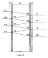
- Figure 2 is a schematic view of a birefringent filter stage incorporating reflective polarizer elements
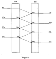
- Figure 3 is a schematic view of an embodiment of the present invention including an assembly of two birefringent stages placed in optical series;
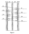
- Figure 4 shows a 3-stage Lyot filter for implementing the present invention
- Figure 5a is a graph showing characteristics of a modeled spectral response of the filter of Figure 4 when each polarizer is a sheet of Sanritz 5618 dichroic polarizer;
- Figure 5b is a graph showing characteristics of a modeled spectral response of the filter of Figure 4 when each polarizer is a piece of Moxtek reflective polarizer;
- Figure 5c is a graph showing characteristics of a modeled spectral response of the filter of Figure 4 when each polarizer consists of a Moxtek reflective polarizer and a sheet of Sanritz 5618 dichroic polarizer, having their transmission axes aligned;
- Figure 6 is a schematic view of an embodiment of a filter assembly having two birefringent networks
- Figure 7a shows the transmission of dichroic glass polarizer material from Codixx AG, model number colorPol 650-1100 AC, along the transmission and absorption axes;
- Figure 7b shows the transmission of Sanritz 5618 polarizer, along the transmission and extinction axes.
- Figure 7c shows the transmission of Moxtek polarizer material PPL05, along the transmission and extinction axes.
- the invention relates to birefringent filters which use reflective polarizers.
- Birefringent filters consist of one or more filter stages in optical series, where each stage has a retarder network and exit polarizer; there is an overall input polarizer in front if the filter is to operate on unpolarized incident light.
- An exemplary birefringent filter is shown in Fig. 1 in which incident light 10 enters through an input polarizer 11, then encounters a first filter stage 12 with an output polarizer 13.
- An optional second stage 14 with an output polarizer 15 receives light from the first filter stage 12.
- the strength of transmitted light beam 16 depends upon ⁇ , the wavelength of incident light 10.
- the invention can be applied to filters using stages of various types, including Lyot stages, Solc stages and arbitary birefringent networks. Also, it may be used on filters where successive polarizers have their axes parallel to one another, or crossed at an angle.
- the reflective polarizer is ideal, meaning it reflects all incident light polarized along a first axis, and transmits all light polarized along an orthogonal axis. More advanced models, which include the effects of partial absorption and transmission of each polarization component at the polarizers, can be made based on the approach shown here, but the key phenomena related to multiple reflection are evident even from this simple analysis.
- Figure 2 shows a birefringent filter stage 20 according to an embodiment of the invention incorporating reflective polarizer elements.
- the primary transmission path in the view of Figure 2 is left-to-right for incident light.
- normally incident rays are drawn at an angle for some portion of their travel. This is done for visual clarity so the rays do not overlap on the drawing.
- the rays travel along paths that depend on the incident light angle, the refractive indices, and the reflector orientations, as is known in the optical art.
- Incident light 10 traveling rightward encounters a reflective input polarizer 21, then a dichroic polarizer 22, and then a birefringent network 23 which transforms its polarization state in a wavelength-dependent manner.
- An exit polarizer is made up of an optional dichroic polarizer 24 followed by a reflective polarizer 25.
- Light which is transmitted without reflection is depicted as beam 26.
- Light which is reflected once at a reflective polarizer is depicted leaving the filter as beam 27a, while light that reflects 3 or 5 times is shown leaving the filter as 27b and 27c, respectively.
- Light which is reflected two times at a reflective polarizer is depicted leaving the filter as beam 28a, while light that reflects 4 or 6 times depicted as 28b and 28c, respectively.
- Higher order odd- and even-order reflections that contribute to beams 27 and 28 are omitted for clarity.
- Light reflecting within the arrangement passes through points 29a - 29g as it progresses.
- the dichroic polarizer elements 22 and 24 are described in terms of transmission for light energy polarized along its transmission axis, and along its extinction axis; denoted as T i ( ⁇ ) and X i ( ⁇ ), respectively, where the subscript i denotes the polarizer identity. Because this analysis considers intensities and energies, rather than electric field strengths, it is not sensitive to interference effects that may be introduced by multiple-reflection rays. This is a reasonable approximation for many situations, where incoherent light is being filtered, where phase interference may be neglected.
- I 29 ⁇ b - c I 0 * a c ⁇ * a ⁇ * T 22 ⁇ * X 22 ( ⁇ ⁇ ) 2 * X 24 ( ⁇ ⁇ ) 2
- I 28 ⁇ a I 0 * a c ( ⁇ ⁇ ) 2 * a ⁇ * T 22 ⁇ * T 24 ⁇ * X 22 ( ⁇ ⁇ ) 2 * X 24 ( ⁇ ⁇ ) 2
- I 29 ⁇ c - d I 0 * a c ⁇ * a ( ⁇ ⁇ ) 2 * T 22 ⁇ * X 22 ( ⁇ ⁇ ) 2 * X 24 ( ⁇ ⁇ ) 4
- I 27 ⁇ b I 0 * a c ( ⁇ ⁇ ) 2 * a ( ⁇ ⁇ ) 2 * T 22 ( ⁇ ⁇ ) 2 * X 22 ( ⁇ ⁇ ) 2 * X 22 ( ⁇ ⁇ ) 4
- I 27 I 0 * a c ( ⁇ ⁇ ) 2 * T 22 ( ⁇ ⁇ ) 2 * X 24 ( ⁇ ⁇ ) 2 / 1 - ⁇
- T 28 / T 26 I 0 * a c ( ⁇ ⁇ ) 2 * T 24 ⁇ * X 22 ( ⁇ ⁇ ) 2 * X 24 ( ⁇ ⁇ ) 2 / 1 - ⁇
- the signal from multiply-reflected beams is also termed "multipath" signal, and it can be problematic in an imaging system, since multipath beams may not come to focus at the same place as ballistic beams. This can degrade the spatial fidelity of the image which is produced, appearing as blur, or halo, or reduced image contrast. When a multispectral image cube contains these artifacts, the quantitative accuracy is affected as well, so spectral unmixing or spectral classification can be degraded.
- ⁇ contains equal terms in X 22 ( ⁇ ) and X 24 ( ⁇ ), as do T mp and T ball . This is consistent with the optics precept that the transmission coefficient for a ray passing through an optical system is independent of which direction the ray is traveled - though the same is not true for its reflection coefficient, as R rh and R lh illustrate.
- FIG. 3 depicts an assembly with light passing through a first birefringent stage 20a on its way toward a second birefringent stage 20b.
- incident light 32 traveling rightward is partially transmitted and partly reflected by each of the first and second birefringent stages 20a, 20b.
- Beam 36 is transmitted without reflection by either stage.
- Beam 37 consists of rays 37a that were reflected by one stage; rays 37b that were reflected from stage to stage 3 times; rays 37c that were reflected from stage to stage 5 times; and higher-order reflections that are omitted for clarity.
- Beam 38 consists of rays 38a, 38b, and 38c that were reflected from stage to stage 2, 4, and 6 times respectively; along with higher-order reflections that are omitted for clarity. Light reflecting between the stages passes through points 39a - 39g as it progresses.
- light which passes through both stages without reflection between stages is depicted as 36, while light which experiences 1, 3, or 5 reflections from one stage to another is depicted as components 37a, 37b, or 37c, and propagates backwards as a reflected beam, and light which experiences 2, 4, or 6 reflections from one stage to another is depicted as components 38a, 38b, or 38c, and propagates forward as a transmitted beam.
- the first term represents the ballistic portion (which underwent no reflections within either stage) and the second portion represents multipath signal, even though it did not reflect between one stage and another.
- subscripts mp and ball are used to denote the multipath and ballistic portion of the signal; when neither of these is present, the entire signal (multipath + ballistic) is described.
- I 38 ⁇ a I 0 * T 20 ⁇ a * T 20 ⁇ b * R 20 ⁇ b L * R 20 ⁇ a
- I 37 ⁇ b I 0 * ( T 20 ⁇ a ⁇ ) 2 * R 20 ⁇ b L * R 20 ⁇ b L * R 20 ⁇ a
- R I 38 ⁇ b I 0 * T 20 ⁇ a * T 20 ⁇ b * R 20 ⁇ b L * R 20 ⁇ a
- I 37 ⁇ c I 0 * ( T 20 ⁇ a ⁇ ) 2 * R 20 ⁇ b L * R 20 ⁇ a R * R 20 ⁇ b L
- I 38 ⁇ c I 0 * T 20 ⁇ a * T 20
- R R ( T 20 ⁇ b ⁇ ) 2 * R 20 ⁇ a R / 1 - R 20 ⁇ b R * R 20 ⁇ b L
- equations [9a] - [9d] one can describe the properties of a pair of stages, given the properties of each stage.
- the properties involved are the ballistic and multipath transmission coefficients, and the reflection coefficients for light incident from either direction.
- Equations [7a] - [7d] are used to calculate the reflection and transmission properties of two stages in isolation, namely the last two stages of a birefringent filter. Then, equations [9a] - [9d] are used to calculate the properties of those two stages, viewed as an assembly. Then, the properties of the previous stage are calculated using equations [7a] - [7d], and equations [9a] - [9d] are used to calculate the properties of an assembly made up of that the previous stage, together with the assembly just analyzed. In this way, one may work backwards to form larger and larger assemblies, to analyze systems containing an arbitrary number of stages.
- Figure 4 shows a 3-stage Lyot filter 40 constructed with quartz retarders 45a, 45b, and 45c having thicknesses of 0.125mm, 0.250mm, and 0.500mm, respectively.
- Incident light 10 encounters entrance polarizer 41, then encounters the retarders 45a-c and polarizers 42a-c in alternating sequence.
- Beam 26 is transmitted without reflection, while beam 27 is reflected and beam 28 is transmitted after two or more reflections within the filter assembly.
- the system of Figure 4 was modeled for various types of polarizer materials.
- the filter 40 was first modeled for the case when each of the polarizers 41 and 42a-c is a dichroic sheet film was used, based on measured transmission and extinction coefficients for Sanritz LLC25618 film. That is, each polarizer 41 and 42a-c is modeled as a sheet of Sanritz 5618 dichroic polarizer. Since this is a dichroic material with no significant reflection, the system was modeled using only the forward-propagating beams, including effects of leakage at the polarizers. According to this first model, the entrance polarizer 41 is arranged to transmit horizontally polarized visible light, and the other polarizers 42a-c are arranged to transmit vertically polarized visible light.
- the results of the above-described first modeled case of Fig. 4 system are shown in Figure 5a .
- the total transmission is shown as 56a, of which essentially none is multipath transmission.
- the primary transmission peak is at 756 nm, and there are side-lobes at shorter wavelengths due to imperfect blocking of adjacent orders, as is known in the art of birefringent filter design. Turning to wavelengths longer than the transmission peak, there is significant leakage due to the imperfect extinction of the visible-range polarizer material, when viewed at infrared wavelengths.
- the system of Figure 4 was modeled for the second case when the polarizers 41 and 42a-c are reflective polarizers, using equations [7a] - [7d] to calculate the response of individual stages, and equations [9a] - [9d] to assemble the response of the overall filter from the stage responses.
- the modeled polarizer properties were based as Moxtek PPL05 reflective polarizer material. The actual measured transmission was used, but the reflection was taken as idealized as described above, namely, that the light reflected and transmitted by this material were perfectly polarized, and that the reflection efficiency was 100 percent.
- Figure 5b depicts the total transmitted signal as 56b and the multipath transmitted component as 58b.
- the multi-path signal is 23% of the total, or approximately 1/3 as large is the desired (ballistic) transmitted signal.
- the multipath energy having taken a longer path with multiple reflections, may not be imaged by an imaging system to the same location as energy which traversed the filter in a single pass.
- the multipath signal 58b forms a greater proportion of the out-of-band light. For example, in the region ⁇ ⁇ 700 nm, the multipath energy is 2.04x greater than the desired ballistic signal. This means that the out-of-band energy is considerably increased by the presence of multipath beams.
- each polarizer 41 and 42a-c includes a Moxtek reflective polarizer and one sheet of dichroic visible film polarizer material placed adjacent to the reflective polarizer, facing toward the incident light.
- the total signal and multipath signal are shown in Figure 5c as curves 56c and 58c, respectively.
- the resulting filter of the third model offers a considerably reduction in multipath energy compared to a reflective-polarizer system of the second model; in a multispectral imaging system this typically improves the image contrast, visual sharpness, detection limit, and quantitative accuracy. So while it is possible to construct a tunable filter using only reflective polarizer materials, use of dichroic sheet adjacent to reflective polarizers essentially eliminates the problem of multipath signals, and reduces unwanted leakage for wavelengths in the stopband, i.e. outside the desired range.
- out-of-band leakage is markedly reduced by the combination of reflective polarizer and dichroic sheet.
- the assembly performs well even at wavelengths where the dichroic sheet polarizer has high leakage - meaning, a high degree of transmission for light polarized along its extinction axis. For example, at 800 nm, even though the dichroic sheet has leakage of 30 percent, the overall assembly has multipath of under 1 percent. This means its transmission very nearly matches that of a filter built with perfect transmissive polarizer. And, at 850 nm, even though the dichroic sheet polarizer is very weakly polarizing - with leakage of 75 percent - the overall assembly has a multipath signal of only 2.6 percent. This is 13x lower than the first model filter shown in Figure 5a , which used only dichroic sheet polarizer.
- placing a dichroic polarizer adjacent to a reflective polarizer enables construction of a filter that operates well over a wider wavelength range than with the dichroic material alone.
- the third modeled version of the Figure 4 filter includes one dichroic sheet on a side of the reflective polarizer facing the incident light
- the dichroic sheet may alternatively be arranged on a side of the reflective polarizer facing away from the incident light.
- Still another embodiment may include a Moxtek reflective polarizer sandwiched between two sheets of Sanritz 5618 dichroic polarizer, having their transmission axes combined.
- FIG. 6 is a schematic view of an assembly 60 which contains two birefringent networks 63a and 63b interposed between entrance polarizers 61 and 62, middle dichroic polarizer 64 and exit polarizers 65 and 66, with the dichroic transmission axis aligned to the adjacent reflective polarizer's transmission axis.
- Polarizers 61 and 66 are reflective type while optional polarizers 62 and 65 are dichroic type.
- Incident light 10 which is transmitted without reflection is depicted as beam 26.
- Light which is reflected once at a reflective polarizer is depicted as beam 27a, while light that reflects 3 or 5 times is depicted as 27b and 27c, respectively.
- Light reflected two times at a reflective polarizer is depicted as beam 28a, while light that reflects 4 or 6 times is depicted as 28b and 28c, respectively.
- Higher order odd- and even-order reflections that contribute to beams 27 and 28 are omitted for clarity.
- Light reflecting between the stages passes through points 67a-k as it progresses.
- ⁇ 1 is used to denote ⁇ for element 63a and the adjacent polarizers
- ⁇ 2 is used to denote ⁇ for element 63b and the adjacent polarizers
- ⁇ c denotes the complement (1 - ⁇ )
- ⁇ 1c denotes the complement of ⁇ 1 .
- I 67 ⁇ a I 0 * T 61 ⁇ T 62 * a 1 ⁇ T 64 + a 1 ⁇ c ⁇ X 64
- I 27 I 0 * T 61 ⁇ T 62 ⁇ T 65 ⁇ T 66 * a 1 ⁇ a 2 ⁇ T 64 + a 1 ⁇ c ⁇ a 2 ⁇ c ⁇ X 64
- I 67 ⁇ b I 0 * T 61 ⁇ T 62 ( X 65 ⁇ ) 2 * a 1 ⁇ a 2 ⁇ c ⁇ T 64 + a 1 ⁇ c ⁇ a 2 ⁇ X 64
- I 67 ⁇ c I 0 * T 61 ⁇ T 62 ( X 65 ⁇ ) 2 * a 1 ⁇ a 2 ⁇ c ⁇ T 64 + a 1 ⁇ c ⁇ a 2 ⁇ X 64
- I 67 ⁇ c I 0 * T 61 ⁇ T 62 ( X
- I 27 I 0 * ( T 61 ⁇ T 62 ⁇ X 65 ⁇ ) 2 * [ a 1 ⁇ a 2 ⁇ c ⁇ T 64 + a 1 ⁇ c ⁇ a 2 ⁇ X 64 ⁇ ] 2 / 1 - ( X 62 ⁇ X 65 ⁇ ) 2 + [ a 1 ⁇ c ⁇ a 2 ⁇ c ⁇ T 64 + a 1 ⁇ a 2 ⁇ X 64 ⁇ ] 2
- I 28 I 0 * T 61 ⁇ T 62 ⁇ T 65 ⁇ T 66 ( X 62 X 65 ⁇ ) 2 * a 1 ⁇ a 2 ⁇ c ⁇ T 64 + a 1 ⁇ c ⁇ a 2 ⁇ X 64 * a 1 ⁇ c ⁇ a 2 ⁇ c ⁇ T 64 + a 1 ⁇ a 2 ⁇ X 64 * a 1 ⁇ a 2 ⁇ c ⁇ T 64 +
- T ball T 61 ⁇ T 62 ⁇ T 65 ⁇ T 66 * a 1 ⁇ a 2 ⁇ T 64 + a 1 ⁇ c ⁇ a 2 ⁇ c ⁇ X 64
- I mp T 61 ⁇ T 62 ⁇ T 65 ⁇ T 66 ( X 62 X 65 ⁇ ) 2 * a 1 ⁇ a 2 ⁇ c ⁇ T 64 + a 1 ⁇ c ⁇ a 2 ⁇ X 64 * a 1 ⁇ c ⁇ a 2 ⁇ c ⁇ T 64 + a 1 ⁇ a 2 ⁇ X 64 * a 1 ⁇ c ⁇ a 2 ⁇ T 64 + a 1 ⁇ a 2 ⁇ X 64 * a 1 ⁇ c ⁇ a 2 ⁇ T 64 + a 1 ⁇ a 2 ⁇ c ⁇ X 64 / 1 - ( X 62 ⁇ X 65 ⁇ ) 2 + [ a 1 ⁇ c
- R R ( T 65 ⁇ T 66 ⁇ X 62 ⁇ ) 2 * [ a 2 ⁇ a 1 ⁇ c ⁇ T 64 + a 2 ⁇ c ⁇ a 1 ⁇ X 64 ⁇ ] 2 / 1 - ( X 62 ⁇ X 65 ⁇ ) 2 + [ a 1 ⁇ c ⁇ a 2 ⁇ c ⁇ T 64 + a 1 ⁇ a 2 ⁇ X 64 ⁇ ] 2
- Such a stage provides a filter action corresponding to two individual birefringent stages, but only requires use of a single dichroic polarizer element 64.
- dichroic sheet polarizer this provides an alternative design to the embodiment described earlier, in which dichroic sheet was placed adjacent to the reflective polarizer. This design is valuable because one may construct a filter having N stages which uses only N/2 pieces of dichroic polarizer, rather than the usual N. This can be valuable when the dichroic film is expensive; or has low optical transmission.
- This design also has low multipath energy, so is generally consistent with high imaging quality and spectral quality. It is possible to further improve it using dichroic sheet film in locations 62 and 65, which act as damping elements to reduce multipath energy. These need not be the same material as the central polarizer 64, and will reduce the multipath signal to some degree even if they may exhibit less extinction than the central polarizer.
- the central polarizer may be a piece of colorpol dichroic glass from Codixx, in optical series with a piece of dichroic visible sheet polarizer; while the damping polarizers 62 and 65 may be Sanritz LLC2-9518.
- the damping polarizers improve multipath levels and the overall filter can be operated over the spectral range from 450 nm - 900 nm.
- Figures 7a - 7c show the transmission and extinction of various polarizers, measured using incident light polarized > 10,000:1, when the polarizer was oriented with its transmission axis along, and orthogonal to, the incident polarization axis. All polarizers were bonded with index-matching optical adhesive, between a pair of windows. The window faces that formed the outer faces of the assembly had been anti-reflection coated to eliminate Fresnel losses.
- Figure 7a shows the transmission of dichroic glass polarizer material from Codixx AG, model number colorPol 650-1100 AC, along the transmission and absorption axes, respectively, as 71a and 72a.
- Figure 7b shows the transmission of Sanritz 5618 polarizer, along the transmission and extinction axes, respectively, as 71b and 72b.
- Figure 7c shows the transmission of Moxtek polarizer material PPL05, along the transmission and extinction axes, respectively, as 71c and 72c.
Landscapes
- Physics & Mathematics (AREA)
- General Physics & Mathematics (AREA)
- Optics & Photonics (AREA)
- Polarising Elements (AREA)
Applications Claiming Priority (1)
| Application Number | Priority Date | Filing Date | Title |
|---|---|---|---|
| US11/986,257 US7982955B2 (en) | 2007-11-20 | 2007-11-20 | Birefringent filter using reflective polarizers and dichroic elements |
Publications (2)
| Publication Number | Publication Date |
|---|---|
| EP2063310A2 true EP2063310A2 (fr) | 2009-05-27 |
| EP2063310A3 EP2063310A3 (fr) | 2010-06-09 |
Family
ID=40445335
Family Applications (1)
| Application Number | Title | Priority Date | Filing Date |
|---|---|---|---|
| EP08169567A Withdrawn EP2063310A3 (fr) | 2007-11-20 | 2008-11-20 | Filtre biréfringent utilisant des polarisateurs réfléchissant et des éléments dichroïques |
Country Status (2)
| Country | Link |
|---|---|
| US (1) | US7982955B2 (fr) |
| EP (1) | EP2063310A3 (fr) |
Cited By (1)
| Publication number | Priority date | Publication date | Assignee | Title |
|---|---|---|---|---|
| CN106037631A (zh) * | 2015-04-01 | 2016-10-26 | 佳能株式会社 | 双折射滤光器单元 |
Families Citing this family (4)
| Publication number | Priority date | Publication date | Assignee | Title |
|---|---|---|---|---|
| US8107152B2 (en) * | 2007-08-29 | 2012-01-31 | Nova Photonics | Electro-optical tunable birefringent filter |
| EP2666039B1 (fr) * | 2011-01-18 | 2017-06-07 | 3M Innovative Properties Company | Pile de films optiques |
| JP2019500651A (ja) * | 2015-12-17 | 2019-01-10 | スリーエム イノベイティブ プロパティズ カンパニー | 反射型バックライト付きディスプレイを備えたミラー |
| WO2023193079A1 (fr) * | 2022-04-09 | 2023-10-12 | Silva Marcelo Favoreto | Ensemble avec lame de roche naturelle translucide appliqué comme revêtement décoratif et dispositif et procédé de production |
Citations (4)
| Publication number | Priority date | Publication date | Assignee | Title |
|---|---|---|---|---|
| US4129357A (en) | 1977-08-11 | 1978-12-12 | Nasa | Partial polarizer filter |
| US4394069A (en) | 1979-06-05 | 1983-07-19 | Beckman Instruments, Inc. | Liquid crystal tuned birefringent filter |
| US4848877A (en) | 1987-09-29 | 1989-07-18 | Cambridge Research And Instrumentation, Inc. | Liquid crystal devices and systems using such devices |
| US5247378A (en) | 1991-06-07 | 1993-09-21 | Peter Miller | Optical retarder having means for determining the retardance of the cell corresponding to the sensed capacitance thereof |
Family Cites Families (6)
| Publication number | Priority date | Publication date | Assignee | Title |
|---|---|---|---|---|
| US5243455A (en) * | 1990-05-11 | 1993-09-07 | The University Of Colorado Foundation, Inc. | Chiral smectic liquid crystal polarization interference filters |
| US6204901B1 (en) | 1997-07-31 | 2001-03-20 | Duke University | Liquid crystal color shutters that include reflective polarizers that pass color components of light of a first polarization and that reflect a majority of color components of light of a second polarization |
| US7336323B2 (en) * | 2005-09-27 | 2008-02-26 | Chemimage Corporation | Liquid crystal filter with tunable rejection band |
| US7859753B2 (en) * | 2005-12-21 | 2010-12-28 | Chem Image Corporation | Optical birefringence filters with interleaved absorptive and zero degree reflective polarizers |
| US7655898B2 (en) * | 2006-11-30 | 2010-02-02 | Cambridge Research & Instrumentation, Inc. | Optical filter assembly with selectable bandwidth and rejection |
| US7826009B2 (en) * | 2006-12-21 | 2010-11-02 | 3M Innovative Properties Company | Hybrid polarizer |
-
2007
- 2007-11-20 US US11/986,257 patent/US7982955B2/en active Active
-
2008
- 2008-11-20 EP EP08169567A patent/EP2063310A3/fr not_active Withdrawn
Patent Citations (4)
| Publication number | Priority date | Publication date | Assignee | Title |
|---|---|---|---|---|
| US4129357A (en) | 1977-08-11 | 1978-12-12 | Nasa | Partial polarizer filter |
| US4394069A (en) | 1979-06-05 | 1983-07-19 | Beckman Instruments, Inc. | Liquid crystal tuned birefringent filter |
| US4848877A (en) | 1987-09-29 | 1989-07-18 | Cambridge Research And Instrumentation, Inc. | Liquid crystal devices and systems using such devices |
| US5247378A (en) | 1991-06-07 | 1993-09-21 | Peter Miller | Optical retarder having means for determining the retardance of the cell corresponding to the sensed capacitance thereof |
Non-Patent Citations (4)
| Title |
|---|
| "Optical Network Synthesis Using Birefringent Crystals. I. Synthesis of Lossless Networks of Equal-Length Crystals", J. OPT. SOC. AM., vol. 54, 1964, pages 1267 |
| E. O. AMMAN: "Optical Network Synthesis Using Birefringent Crystals. IV. Synthesis of Lossless Double-Pass Networks", J. OPT. SOC. AM., vol. 56, no. 7, 1966, pages 952 |
| E. O. AMMAN: "Synthesis of Optical Birefringent Networks", PROGRESS IN OPTICS, vol. IX, 1971, pages 123 - 177 |
| S. E. HARRIS; E. O. AMMAN; I. C. CHANG: "Optical Network Synthesis Using Birefringent Crystals. III. Some General Properties of Lossless Birefringent Networks", J. OPT. SOC. AM., vol. 56, 1966, pages 943 |
Cited By (3)
| Publication number | Priority date | Publication date | Assignee | Title |
|---|---|---|---|---|
| CN106037631A (zh) * | 2015-04-01 | 2016-10-26 | 佳能株式会社 | 双折射滤光器单元 |
| US10274744B2 (en) | 2015-04-01 | 2019-04-30 | Canon Kabushiki Kaisha | Birefringent filter unit |
| CN106037631B (zh) * | 2015-04-01 | 2019-08-30 | 佳能株式会社 | 双折射滤光器单元 |
Also Published As
| Publication number | Publication date |
|---|---|
| US20090128909A1 (en) | 2009-05-21 |
| EP2063310A3 (fr) | 2010-06-09 |
| US7982955B2 (en) | 2011-07-19 |
Similar Documents
| Publication | Publication Date | Title |
|---|---|---|
| RU2124746C1 (ru) | Дихроичный поляризатор | |
| US7859754B2 (en) | Wideband dichroic-filter design for LED-phosphor beam-combining | |
| EP2062018B1 (fr) | Retardateur sensiblement achromatique à compensation autonome de l'angle de déviation | |
| JP7187745B2 (ja) | 両側において高い反射率を有するワイヤグリッド偏光子 | |
| EP2063310A2 (fr) | Filtre biréfringent utilisant des polarisateurs réfléchissant et des éléments dichroïques | |
| US20040075903A1 (en) | Optical devices employing beam folding with polarizing splitters | |
| CN116088082A (zh) | 紧凑型基于偏振的多通光学架构 | |
| JP4574439B2 (ja) | 偏光分離素子及びそれを有する投影装置 | |
| CN108469693A (zh) | 一种双通道声光可调谐滤波器及高光谱成像装置 | |
| CA2344021C (fr) | Separateur ou coupleur de faisceaux polarises | |
| US8879150B1 (en) | Optical thin-film polarizing bandpass filter | |
| WO2020153843A1 (fr) | Optique de modulation de polarisation | |
| US6577445B1 (en) | Composite birefringent crystal and filter | |
| JP5023707B2 (ja) | チューナブルフィルタ、光源装置、及びスペクトル分布測定装置 | |
| US20210116368A1 (en) | Optical inspection | |
| JP3789765B2 (ja) | ダブルパス複屈折フィルタ及びその操作方法 | |
| US20040179265A1 (en) | Circulator and polarization beam combiner | |
| JP5136185B2 (ja) | 波長フィルタ | |
| Parretta | All the light from the Newton’s Prism: Effects of the multiple internal reflections | |
| US7400448B2 (en) | Birefringent spectral filter | |
| US8867130B1 (en) | Polarization device for vacuum ultraviolet or shorter wavelengths | |
| RU2297652C2 (ru) | Способ спектральной фильтрации излучения | |
| US20130094087A1 (en) | Tunable filter using a wave plate | |
| JPH03221917A (ja) | 画像表示装置 | |
| RU2644631C1 (ru) | Светосильный двухкристальный акустооптический монохроматор |
Legal Events
| Date | Code | Title | Description |
|---|---|---|---|
| PUAI | Public reference made under article 153(3) epc to a published international application that has entered the european phase |
Free format text: ORIGINAL CODE: 0009012 |
|
| AK | Designated contracting states |
Kind code of ref document: A2 Designated state(s): AT BE BG CH CY CZ DE DK EE ES FI FR GB GR HR HU IE IS IT LI LT LU LV MC MT NL NO PL PT RO SE SI SK TR |
|
| AX | Request for extension of the european patent |
Extension state: AL BA MK RS |
|
| PUAL | Search report despatched |
Free format text: ORIGINAL CODE: 0009013 |
|
| AK | Designated contracting states |
Kind code of ref document: A3 Designated state(s): AT BE BG CH CY CZ DE DK EE ES FI FR GB GR HR HU IE IS IT LI LT LU LV MC MT NL NO PL PT RO SE SI SK TR |
|
| AX | Request for extension of the european patent |
Extension state: AL BA MK RS |
|
| 17P | Request for examination filed |
Effective date: 20101209 |
|
| AKX | Designation fees paid |
Designated state(s): AT BE BG CH CY CZ DE DK EE ES FI FR GB GR HR HU IE IS IT LI LT LU LV MC MT NL NO PL PT RO SE SI SK TR |
|
| 17Q | First examination report despatched |
Effective date: 20170203 |
|
| STAA | Information on the status of an ep patent application or granted ep patent |
Free format text: STATUS: THE APPLICATION IS DEEMED TO BE WITHDRAWN |
|
| 18D | Application deemed to be withdrawn |
Effective date: 20170614 |