EP2063336B2 - Dispositif d'entraînement pour un dispositif d'obscurcissement - Google Patents
Dispositif d'entraînement pour un dispositif d'obscurcissement Download PDFInfo
- Publication number
- EP2063336B2 EP2063336B2 EP08019788.2A EP08019788A EP2063336B2 EP 2063336 B2 EP2063336 B2 EP 2063336B2 EP 08019788 A EP08019788 A EP 08019788A EP 2063336 B2 EP2063336 B2 EP 2063336B2
- Authority
- EP
- European Patent Office
- Prior art keywords
- sensor
- drive
- counting
- arrangement
- current
- Prior art date
- Legal status (The legal status is an assumption and is not a legal conclusion. Google has not performed a legal analysis and makes no representation as to the accuracy of the status listed.)
- Active
Links
Images


Classifications
-
- E—FIXED CONSTRUCTIONS
- E06—DOORS, WINDOWS, SHUTTERS, OR ROLLER BLINDS IN GENERAL; LADDERS
- E06B—FIXED OR MOVABLE CLOSURES FOR OPENINGS IN BUILDINGS, VEHICLES, FENCES OR LIKE ENCLOSURES IN GENERAL, e.g. DOORS, WINDOWS, BLINDS, GATES
- E06B9/00—Screening or protective devices for wall or similar openings, with or without operating or securing mechanisms; Closures of similar construction
- E06B9/56—Operating, guiding or securing devices or arrangements for roll-type closures; Spring drums; Tape drums; Counterweighting arrangements therefor
- E06B9/80—Safety measures against dropping or unauthorised opening; Braking or immobilising devices; Devices for limiting unrolling
- E06B9/82—Safety measures against dropping or unauthorised opening; Braking or immobilising devices; Devices for limiting unrolling automatic
- E06B9/88—Safety measures against dropping or unauthorised opening; Braking or immobilising devices; Devices for limiting unrolling automatic for limiting unrolling
-
- G—PHYSICS
- G05—CONTROLLING; REGULATING
- G05B—CONTROL OR REGULATING SYSTEMS IN GENERAL; FUNCTIONAL ELEMENTS OF SUCH SYSTEMS; MONITORING OR TESTING ARRANGEMENTS FOR SUCH SYSTEMS OR ELEMENTS
- G05B19/00—Program-control systems
- G05B19/02—Program-control systems electric
- G05B19/18—Numerical control [NC], i.e. automatically operating machines, in particular machine tools, e.g. in a manufacturing environment, so as to execute positioning, movement or co-ordinated operations by means of program data in numerical form
- G05B19/406—Numerical control [NC], i.e. automatically operating machines, in particular machine tools, e.g. in a manufacturing environment, so as to execute positioning, movement or co-ordinated operations by means of program data in numerical form characterised by monitoring or safety
- G05B19/4067—Restoring data or position after power failure or other interruption
-
- E—FIXED CONSTRUCTIONS
- E06—DOORS, WINDOWS, SHUTTERS, OR ROLLER BLINDS IN GENERAL; LADDERS
- E06B—FIXED OR MOVABLE CLOSURES FOR OPENINGS IN BUILDINGS, VEHICLES, FENCES OR LIKE ENCLOSURES IN GENERAL, e.g. DOORS, WINDOWS, BLINDS, GATES
- E06B9/00—Screening or protective devices for wall or similar openings, with or without operating or securing mechanisms; Closures of similar construction
- E06B9/56—Operating, guiding or securing devices or arrangements for roll-type closures; Spring drums; Tape drums; Counterweighting arrangements therefor
- E06B9/68—Operating devices or mechanisms, e.g. with electric drive
-
- G—PHYSICS
- G05—CONTROLLING; REGULATING
- G05B—CONTROL OR REGULATING SYSTEMS IN GENERAL; FUNCTIONAL ELEMENTS OF SUCH SYSTEMS; MONITORING OR TESTING ARRANGEMENTS FOR SUCH SYSTEMS OR ELEMENTS
- G05B2219/00—Program-control systems
- G05B2219/30—Nc systems
- G05B2219/36—Nc in input of data, input key till input tape
- G05B2219/36467—Teach and store time needed from open to closed and closed to open position
-
- G—PHYSICS
- G05—CONTROLLING; REGULATING
- G05B—CONTROL OR REGULATING SYSTEMS IN GENERAL; FUNCTIONAL ELEMENTS OF SUCH SYSTEMS; MONITORING OR TESTING ARRANGEMENTS FOR SUCH SYSTEMS OR ELEMENTS
- G05B2219/00—Program-control systems
- G05B2219/30—Nc systems
- G05B2219/45—Nc applications
- G05B2219/45015—Roller blind, shutter
Definitions
- the invention relates to a drive arrangement for a darkening device or safety device according to the preamble of claim 1.
- the drive arrangement in question can be used for a large number of darkening devices or safety devices. It is only essential that the darkening device or safety device has an adjustable closure element. Examples of such an adjustable closure element are shutters, venetian blinds, window shutters, awnings, roller doors or roller curtains.
- a well-known drive arrangement designed in the manner of a tubular motor (EP 0 552 459 A1 ) is primarily used for the motorized adjustment of a roller shutter.
- the drive arrangement is equipped with a drive motor and a gearbox connected downstream of the drive motor.
- the drive motor is associated with a drive control with a distance measuring arrangement for determining the current position of the roller shutter.
- determination of the current position means that a value is determined as a measure of the current position, which value can be compared with a stored desired position value.
- a first incremental sensor element is assigned to the winding shaft of the roller shutter to determine the rough position of the roller shutter.
- the sensor element is designed as a reed sensor, to which magnets arranged in a ring connected to the winding shaft are assigned. The magnets are distributed at relatively wide intervals over the circumference of the ring, so that with this sensor element only the approximate position - rough position - of the shutter can be determined.
- a second sensor element is provided in the known drive arrangement, which is assigned to the motor shaft of the drive motor.
- An advantage of the known drive arrangement is the fact that, despite the simple structure of the sensor elements--incremental sensors--a comparatively high level of accuracy can be achieved. This is due in particular to the fact that the sensor pulses of the first sensor element are to be understood to a certain extent as periodic reference pulses. All measurement inaccuracies are eliminated when a reference pulse occurs.
- multi-turn rotary encoders are also known, the measuring range of which correspondingly includes a plurality of revolutions.
- these are expensive and on the other hand they are often not sufficiently accurate compared to the above distance measuring arrangement.
- the drive arrangement in question can also be designed as a belt winder for a blackout device such as a roller shutter.
- the basic structure of such Gurtwicklers is in the DE 299 21 653 U1 shown.
- the well-known drive arrangement ( WO 03/078784 A1 ), From which the invention is based, is assigned to a roller door or the like.
- the path measuring arrangement In order to determine the rough position of the roller shutter, the path measuring arrangement first counts the structural elements which are passing a sensor device. To determine the fine position of the roller door, a time measuring device is also provided, which measures the time after the last structural element has passed.
- a disadvantage of the known drive arrangement is the fact that restarting after the drive motor has been switched off or after a power failure can cause problems, particularly if the closure element sags slightly. This is because such a sagging cannot be detected with the known drive arrangement.
- the invention is based on the problem of designing and developing the known drive arrangement in such a way that there is a high level of operational reliability, in particular after the drive motor has been switched off or after a power failure.
- the drive control has an intermediate memory and always or cyclically stores the current counter reading and possibly the current time interval and that the intermediate memory also stores the current sensor signal or the current sensor signals of the sensor device. With the additional storage of the current sensor signal or the current sensor signals, it is easy to determine whether the closure element has been adjusted in the switched-off state and whether the counter reading may need to be corrected.
- a particularly simple signal evaluation is possible, since a pulse of the pulse-like sensor signals always has a rising edge and a falling edge, which can be easily detected by the control system.
- a square-wave course of the sensor pulses is particularly advantageous.
- the drive arrangement is configured as a tubular motor.
- the high compactness of the proposed distance measuring arrangement can be used particularly advantageously for such a tubular motor.
- the drive arrangement is provided as a belt winder for a darkening device such as a roller shutter.
- a darkening device such as a roller shutter.
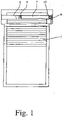
- the proposed solution is shown in the drawing using a blackout device with an adjustable closure element 1 designed as a roller shutter.
- the proposed drive arrangement can be used for many variants of darkening devices or safety devices.
- An exemplary selection was given in the introductory part of the description.
- the drive arrangement has a drive motor 2 and a gear 3 connected downstream of the drive motor 2 for motorized adjustment of the closure element 1 . If necessary, a downstream transmission 3 can also be dispensed with.
- a drive control 4 is assigned to the drive motor 2 , the drive control 4 having a distance measuring arrangement for determining the position of the closure element 1 .
- the path measuring arrangement is equipped with a sensor device 5 and a position counter.
- a sensor device 5 is shown schematically in 4 shown.
- the sensor device 5 consists of at least one sensor element, here and preferably of two sensor elements A, B.
- the sensor device 5 When the closure element 1 is adjusted, the sensor device 5 generates periodic sensor signals that provide counter events for the position counter and when a counter event occurs in the position counter, depending on the direction of adjustment, a high - or effect counting down by one counting step. The count accordingly provides a measure of the rough position.
- the path measuring arrangement also has a time measuring device, with which, triggered by a counting event, the current time interval - time interval - to precisely this counting event can be measured. It is initially assumed that the displacement speed of the closure element 1 is essentially constant, so that the time interval together with the total counter reading provides an exact measure of the displacement path of the closure element 1 .
- the counting events are preferably repeated periodically in accordance with the sensor signals. In principle, however, it is also conceivable for the counting events to be defined in such a way that a counting event occurs only once or twice during a complete adjustment process. An application for this is explained further below.
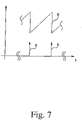
- the principle of measuring the time interval shows 7 by way of example using two counting events E. Shortly before the occurrence of the first counting event E shown, a measurement of the time interval T is already running, which is reset when the counting event E occurs and starts again. This process is repeated when the second counting event E occurs and preferably for all subsequent counting events.
- the representation in 7 illustrates that the respective current time interval, assuming a constant adjustment speed, represents a measure of the adjustment path that the closure element 1 has covered since the last counting event E.
- time-measuring device has a counter to which a clock pulse is applied by a clock generator and which is preferably reset with each counting event and restarts the counting process.
- the sensor device 5 it is sufficient for the sensor device 5 to be equipped with only one sensor element in order to be able to generate the sensor signals providing the counting events. It is advantageous to provide at least two, preferably exactly two, sensor elements A, B, particularly against the background that the adjustment direction of the closure element 1 can also be determined using a plurality of sensor elements. This shows 4 exemplary.
- the - at least one - sensor element A, B is designed so that it generates pulse-like sensor signals during a motorized adjustment of the closure element 1, which preferably have a rising and a falling signal edge within a pulse.
- Such signal edges can be processed well in terms of control technology.
- the sensor signals can be sinusoidal, triangular, sawtooth or similar signals.
- the term "signal edge" is to be understood in a correspondingly broad manner in the present case. In this context, it is particularly advantageous if the sensor signals are rectangular and can only assume a maximum level and a minimum level.
- figure 5 shows the signal curves of the sensor elements A, B when moving upwards.
- 6 shows the signal curves of the sensor elements A, B during downward movement. It can be seen from these representations that the signal curves of the sensor elements A, B are essentially rectangular.
- the respective sensor element A, B is preferably designed as a proximity sensor or as a proximity switch.
- a preferred variant consists in the sensor elements A, B being designed as magnetically activatable sensors, preferably as reed sensors or as Hall sensors.
- the sensor elements A, B are designed as capacitive or inductive sensors.
- a third preferred variant provides that the sensor elements A, B are designed as optical sensors. Of course, this also applies if only one sensor element A should be provided.
- the sensor device 5 may be assigned a triggering element arrangement 5a with at least one triggering element M, preferably with at least one magnet M.
- a triggering element arrangement 5a with at least one triggering element M, preferably with at least one magnet M.
- sensor elements A, B designed as a reed sensor or as a Hall sensor and in 4 shown.
- An adjustment of the closure element 1 here triggers a movement of the triggering element arrangement 5a relative to the sensor device 5, here in a rotation of the magnets M, and thus the generation of the periodic sensor signals.
- the structural design is explained further below.
- the rising signal edges and/or the falling signal edges of the sensor signals each form a counting event for the position counter. It is also conceivable that a counting event is defined by the result of a logical operation between the sensor signals of a sensor element A and the sensor signals of another sensor element B.
- the exemplary embodiment illustrated provides that the falling and rising signal edges of both sensor element A and sensor element B each have a counting event E form.
- the resulting count events E and the respective resulting counter reading Z are shown as an example.
- the representation of the counter reading Z forms a step form whose step width is not constant, which is due to different time intervals between two counting events.
- the reason for this is that the rectangular pulses formed by the sensor elements A, B are not ideally symmetrical. This is again due to the fact that the two sensor elements A, B are not arranged exactly in the center of the movement of the rotating magnets M. However, this arrangement was chosen in order to produce a phase shift between the sensor signals, which is still to be explained.
- control output is to be understood broadly.
- this control output can provide a signal that goes back to the actuation of a direction switch by the user.
- it can also be the output of a memory in which the current direction information is stored.
- the above preferred variant for detecting the adjustment direction can be implemented easily and inexpensively. This is not least due to the fact that only a single sensor element is required.
- a disadvantage, however, is the fact that the direction of an adjustment of the closure element 1 that has taken place when the drive motor 2 is switched off cannot be immediately recognized.
- the additional sensor element B can be used to identify the current direction of adjustment, so that the direction of adjustment can be determined without recourse to the drive controller 4 .
- the sensor signals of the two sensor elements A, B are preferably phase-shifted relative to one another by approximately 25% of a signal period. With a suitable pulse width, such a phase shift allows the counting direction to be determined from a signal edge of sensor element A, which forms a counting event, and the corresponding signal value of sensor element B.
- the signal level of sensor element B makes it easy to see whether a rising or falling signal edge of sensor element A, which here and preferably forms a counting event E for the position counter, should trigger counting up or down in the position counter.
- the counting event formed by a signal edge of the sensor pulse of one sensor element A, B causes the position counter to count up or down by one counting step depending on the current sensor signal of the other sensor element B, A.
- the counting events generated by the sensor device 5 not only bring about a counting process in the position counter. As already indicated, they also serve to trigger the measurement of the time interval in the time-measuring device.
- each individual counting event triggers the measurement of the time interval.
- the latter variant goes back to the consideration that determining the exact position of the closure element 1 is not required in the entire adjustment range of the closure element 1 . For example, it is not necessary to approach an intermediate layer with millimeter precision.
- the closure element 1 is preferably adjustable between a lower end position and an upper end position, with the two end positions having a lower counter reading and a lower time interval or an upper counter reading and an upper time interval are assigned.
- the above determination of the position of the closure element 1 is primarily used for the automatic operation of the closure element 1 with a corresponding automatic switch-off of the drive motor 2.
- the drive controller 4 has a position memory for storing the position of the closure element 1 in end positions and/or has in intermediate layers and that a counter reading can be stored in the position memory, if necessary with a time interval. Whether the time interval is also saved depends on the accuracy with which the respective positions are to be approached. In order to save storage space, provision can be made, for example, for the time interval to be stored only when the end positions are stored and not when intermediate positions are stored.
- the position memory is preferably filled with data using the teach-in process.
- a desired position of the closure element 1 is approached manually via appropriate input keys.
- the corresponding counter reading and/or time interval values are transferred to the position memory.
- the drive controller 4 compares the current counter reading with the stored counter reading and, if they match, switches off the drive motor 2 subject to a possibly provided check of the time interval. In particular when approaching an end position, preferably only when approaching an end position, it is provided that the drive controller 4 only switches off the drive motor 2 when the current time interval also matches the stored time interval.
- a braking distance can advantageously also be taken into account. This means that the drive motor 2 is switched off shortly before the stored time interval is reached. This can lead to a significant increase in positioning accuracy.
- the drive controller 4 has a buffer store and always or cyclically stores the respective current counter reading and, if applicable, the current time interval. Furthermore, it can also preferably be provided that the buffer store additionally stores the current sensor signal or the current sensor signals of the sensor device 5 . In terms of hardware, the intermediate memory can also coincide with the position memory.
- the drive controller 4 compares sensor signal or the current sensor signals of the sensor device 5 with the sensor signal stored in the buffer store or with the sensor signals stored in the buffer store when the drive motor 2 is restarted after it has been switched off or after a power failure Compares sensor signals and, in the event of a deviation due to an adjustment during the switched-off state, triggers a correction routine for the correction of the counter reading, if necessary.
- the drive control 4 in the correction routine checks the current sensor signal or the current sensor signals, possibly as a signal sequence together with the sensor signal stored in the buffer memory or with the sensor signals stored in the buffer memory for the occurrence of a counting event and accordingly in the counter counting up or down by one count catches up. It is assumed here that the values for the sensor signals present in the intermediate memory immediately precede the current sensor signals and correspondingly form a signal sequence with the current sensor signals.
- a position P is shown by a broken line. If the drive motor 2 stops in this position due to a power failure, the counter reading, possibly the time interval and the signal values of the sensor elements A, B for the position P are preferably available in the buffer when restarting. In this example, the maximum level is stored for sensor element A and the maximum level for sensor element B as well. If the closure element 1 has dropped slightly due to its weight during the power failure, the maximum level is still measured for the sensor element A when restarting, but the minimum level for the sensor element B is now measured.
- the counter reading can be made up for in the correct direction with some probability when the vehicle starts up again. It is initially provided that each counting event, which is formed by a falling and rising edge of the—single—sensor signal, triggers the measurement of the time interval in the time-measuring device. In addition to the meter reading and the sensor signal, the time interval is also stored in the buffer and the last direction of adjustment.
- the drive controller 4 If the drive controller 4 now determines that the sensor signal has changed in the switched-off state, the drive controller 4 starts a correction routine again.
- the correction routine the time interval present in the intermediate memory is used to determine whether the arrangement is closer to the next counting event or closer to the last counting event before it is switched off. It is now assumed that, during the switched-off state, an adjustment has taken place in the direction of the next counting event and a corresponding counting process in the position counter has been carried out. With some probability, this leads to the correct result, provided that the counting events are sufficiently far apart from one another, viewed over the displacement of the closure element 1 .
- the measurement of the time interval explained above has another advantage in general. This is because it can also be used in order to detect any undesired braking or stopping of the closure element 1 . Such a braking or stopping of the closure element 1 can occur, for example, in the event of pinching. Another case that is relevant here is explained below in connection with the realization of a freewheel in the drive train between the drive motor 2 and the closure element 1 .
- the drive controller 4 detects that a limit time interval has been exceeded and then switches off the drive motor 2.
- the limit time interval is a constant value, which is preferably stored in a memory.
- the limit time interval depends on the current adjustment direction and/or on the current adjustment range and/or on the current adjustment speed.
- several limit time intervals can be stored in a memory for this purpose.
- the drive controller 4 determines the limit time interval constantly or at predetermined times.
- closure element 1 can be designed as a roller shutter, as a roller shutter, as an awning or the like.
- closure element 1 can preferably be wound onto a winding shaft 6 by means of the drive arrangement.
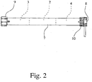
- the drive arrangement is designed as a tubular motor with a tubular housing 7 , the tubular motor being arranged in the winding shaft 6 in the installed state, in particular being pushed into the winding shaft 6 .
- the tubular motor preferably has at one end a tubular motor head 8 for the connection to a stationary counter bearing and at the other end a driver 9 for the drive-related coupling to the winding shaft 6 .
- the tubular motor is further preferably equipped with an adapter ring 10 in the region of the tubular motor head 8, which can also be rotated relative to the tubular motor and via which the winding shaft 6 is rotatably mounted relative to the tubular motor in the assembled state.
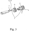
- the sensor device 5 is assigned to a component in the drive train between the drive motor 2 and the closure element 1 .
- the sensor device 5 is assigned to the winding shaft 6 .
- the magnetic ring 11 is here and preferably associated with the trigger element arrangement 5a.
- the triggering elements designed as magnets M are arranged in the magnetic ring 11 and are distributed over the circumference of the magnetic ring 11 .
- the triggering element arrangement 5a can also be arranged on or in the adapter ring 10 . In this case, all explanations for the magnetic ring 11 apply accordingly to the adapter ring 10.
- the sensor device 5 in particular the sensor elements A, B, are essentially surrounded by the magnetic ring 11, so that the magnets M interact optimally with the sensor device 5.
- the sensor elements A, B of the in 4 Sensor device 5 shown are arranged essentially in a central plane of the magnetic ring 11, the axis of the magnetic ring 11 lying in this central plane. In a particularly preferred embodiment, however, it is provided that the sensor elements A, B are offset from the center plane, preferably in a plane that is offset from the center plane. It can thus be achieved that the magnets M each pass closer to the respective sensor element A, B.
- the magnetic ring 11 is in 4 shown schematically. It is equipped with the already explained magnets M assigned to the sensor elements A, B over its circumference. Here and preferably four magnets M are provided. In a particularly preferred embodiment, two magnets M are provided. The magnets M are advantageously distributed evenly over the circumference of the magnet ring 11 . In principle, however, it is also conceivable that an uneven distribution over the circumference of the magnetic ring 11 is provided.
- magnets M in such a way that one pole of a magnet M is located radially inside and the other pole of this magnet M is located radially outside.
- magnets M lying next to one another in particular magnets M lying opposite one another, should have opposite polarity. This means that in the case of a magnet M the north pole is radially inward and the south pole is radially outward and in the respective opposite magnet M the north pole is radially outward and the south pole is radially inward.
- the arrangement shown also shows that the sensor elements A, B are arranged on the same circuit board as the drive controller 4 in other respects. This leads to an assembly-friendly structure.
- drive motor 2 is coupled in terms of drive to the driver 9 via a freewheel.
- This freewheel is preferably a freewheel limited on both sides, which more preferably allows the driver 9 to rotate by about 30° without the drive shaft of the drive motor 2 also rotating.
- the arrangement with a freewheel in connection with the monitoring of the time interval for exceeding a limit time interval is therefore very general, but in particular in the case of a closure element 1 configured as a roller shutter, advantageous.
- a reduction in the adjustment speed of the closure element 1 caused by reaching an end position, being trapped or the like causes the limit time interval to be exceeded and thus the drive motor 2 to be switched off.
- This is advantageously associated with running through the freewheel when running down.
- the proposed drive arrangement can in principle also be designed as a belt winder for a darkening device such as a roller shutter.
- a darkening device such as a roller shutter.
- the belt winder is equipped with a housing and, located therein, a reel for winding up a belt webbing, the reel being drivingly coupled to a drive motor.
- the release element (M) in particular a magnet (M) of the release element arrangement, is arranged on the reel.
- the path measuring arrangement does not require any kind of additional sensor. This is of particular importance for the very compact belt winders.
Landscapes
- Engineering & Computer Science (AREA)
- Structural Engineering (AREA)
- Architecture (AREA)
- Civil Engineering (AREA)
- Human Computer Interaction (AREA)
- Manufacturing & Machinery (AREA)
- Physics & Mathematics (AREA)
- General Physics & Mathematics (AREA)
- Automation & Control Theory (AREA)
- Operating, Guiding And Securing Of Roll- Type Closing Members (AREA)
Claims (10)
- Arrangement d'entraînement pour un système d'occultation ou un système de sécurité comprenant un élément de fermeture (1) positionnable tel qu'un volet roulant ou similaire, un moteur d'entraînement (2) et éventuellement un engrenage (3) monté à la suite du moteur d'entraînement (2) étant prévus pour le positionnement motorisé de l'élément de fermeture (1), une commande d'entraînement (4) étant associée au moteur d'entraînement (2) et la commande d'entraînement (4) possédant un arrangement de mesure de course destiné à déterminer la position de l'élément de fermeture (1), l'arrangement de mesure de course possédant un dispositif de détection (5) et un compteur de positions pour la détermination de la position approximative, le dispositif de détection (5) générant des signaux de détecteur périodiques lors d'un positionnement motorisé de l'élément de fermeture (1), lesquels fournissent de préférence des événements de comptage périodiques pour le compteur de positions, et la survenue d'un événement de comptage dans le compteur de positions provoquant une incrémentation ou une décrémentation d'un pas de comptage, suivant le sens du positionnement, l'arrangement de mesure de course possédant un dispositif de mesure du temps pour la détermination de la position précise qui, lorsqu'il est déclenché par un événement de comptage, permet de mesurer l'écart dans le temps - l'intervalle de temps - actuel par rapport à cet événement de comptage, la commande d'entraînement (4) possédant une mémoire temporaire et mémorisant systématiquement ou cycliquement l'état de comptage actuel respectif et éventuellement l'intervalle de temps actuel,
caractérisé
en ce que la mémoire temporaire mémorise en plus le signal de détecteur actuel ou les signaux de détecteur actuels du dispositif de détection (5) et en ce que l'arrangement est affecté de telle sorte que la commande d'entraînement (4), lors d'un redémarrage du moteur d'entraînement (2) après une mise hors circuit ou après une panne électrique, compare le signal de détecteur actuel ou les signaux de détecteur actuels du dispositif de détection (5) avec le signal de détecteur mémorisé dans la mémoire temporaire ou avec les signaux de détecteur mémorisés dans la mémoire temporaire et, en présence d'un écart en raison d'un positionnement pendant l'état hors circuit, déclenche une routine de correction en vue de la correction éventuellement nécessaire de l'état de comptage. - Arrangement d'entraînement selon la revendication 1, caractérisé en ce que le dispositif de détection (5) comprend au moins un élément de détection (A, B), en ce que l'élément de détection (A, B), lors d'un positionnement motorisé de l'élément de fermeture (1), génère des signaux de détecteur de type impulsionnel qui présentent de préférence un front de signal montant et un front de signal descendant à l'intérieur d'une impulsion, et de préférence en ce que les signaux de détecteur présentent un tracé rectangulaire.
- Arrangement d'entraînement selon la revendication 1 ou 2, caractérisé en ce que l'élément de détection (A, B) est configuré sous la forme d'un détecteur pouvant être activé magnétiquement, de préférence sous la forme d'un détecteur Reed ou d'un détecteur à effet Hall, ou en ce que l'élément de détection (A, B) est configuré sous la forme d'un détecteur capacitif ou inductif, ou en ce que l'élément de détection (A, B) est configuré sous la forme d'un détecteur optique.
- Arrangement d'entraînement selon l'une des revendications précédentes, caractérisé en ce qu'un arrangement d'éléments de déclenchement (5a) comprenant au moins un élément de déclenchement (M), comprenant de préférence au moins un aimant (M) est associé au dispositif de détection (5) et en ce qu'un positionnement de l'élément de fermeture (1) déclenche un mouvement de l'arrangement d'éléments de déclenchement (5a) par rapport au dispositif de détection (5) et ainsi la génération des signaux de détecteur périodiques.
- Arrangement d'entraînement selon la revendication 2 et éventuellement selon la revendication 3 ou 4, caractérisé en ce que l'arrangement est affecté de telle sorte que les fronts de signal montants et/ou les fronts de signal descendants des signaux de détecteur forment respectivement un événement de comptage pour le compteur de positions.
- Arrangement d'entraînement selon la revendication 2 et éventuellement selon l'une des revendications 3 à 5, caractérisé en ce que l'arrangement est affecté de telle sorte que l'événement de comptage formé par les signaux de détecteur provoque une incrémentation ou une décrémentation d'un pas de comptage dans le compteur de positions en fonction de l'état d'une sortie de commande de la commande d'entraînement (4) qui forme le sens du positionnement.
- Arrangement d'entraînement selon l'une des revendications précédentes, caractérisé en ce que le dispositif de détection (5) comprend deux éléments de détection (A, B) et en ce que les signaux de détecteur des deux éléments de détection (A, B) sont déphasés l'un par rapport à l'autre lors d'un positionnement de l'élément de fermeture (1), de préférence en ce que l'événement de comptage formé par un front de signal d'une impulsion de détecteur de l'un des éléments de détection (A, B) provoque une incrémentation ou une décrémentation d'un pas de comptage dans le compteur de positions en fonction du signal de détecteur actuel de l'autre élément de détection (B, A).
- Arrangement d'entraînement selon l'une des revendications précédentes, caractérisé en ce que la commande d'entraînement (4) possède une mémoire de position destinée à mémoriser la position de l'élément de fermeture (1) dans les positions finales et/ou dans les positions intermédiaires et en ce qu'un état de comptage peut être mémorisé dans la mémoire de position, éventuellement avec un intervalle de temps.
- Arrangement d'entraînement selon la revendication 8, caractérisé en ce que l'arrangement est affecté de telle sorte que la commande d'entraînement (4), en atteignant une position finale et/ou intermédiaire mémorisée dans la mémoire de position, compare l'état de comptage actuel avec l'état de comptage mémorisé et, en cas de concordance, met le moteur d'entraînement (2) hors circuit sous réserve d'un contrôle éventuellement prévu de l'intervalle de temps, de préférence que la commande d'entraînement (4) ne met le moteur d'entraînement (2) hors circuit, notamment en atteignant une position finale, que si, en plus, l'intervalle de temps actuel coïncide avec l'intervalle de temps mémorisé.
- Arrangement d'entraînement selon l'une des revendications précédentes, caractérisé en ce que l'arrangement est affecté de telle sorte que la commande d'entraînement (4), au cours de la routine de correction, vérifie le signal de détecteur actuel ou les signaux de détecteur actuels éventuellement sous la forme d'une séquence de signaux conjointement avec le signal de détecteur mémorisé dans la mémoire temporaire ou avec les signaux de détecteur mémorisés dans la mémoire temporaire pour y déceler la survenance d'un événement de comptage et rattrape en conséquence une incrémentation ou une décrémentation d'un pas de comptage dans le compteur de positions.
Applications Claiming Priority (2)
| Application Number | Priority Date | Filing Date | Title |
|---|---|---|---|
| DE202007015933 | 2007-11-13 | ||
| DE202007016283U DE202007016283U1 (de) | 2007-11-13 | 2007-11-20 | Antriebsanordnung für eine Verdunkelungsvorrichtung |
Publications (4)
| Publication Number | Publication Date |
|---|---|
| EP2063336A2 EP2063336A2 (fr) | 2009-05-27 |
| EP2063336A3 EP2063336A3 (fr) | 2010-01-06 |
| EP2063336B1 EP2063336B1 (fr) | 2016-02-10 |
| EP2063336B2 true EP2063336B2 (fr) | 2022-06-22 |
Family
ID=40490604
Family Applications (1)
| Application Number | Title | Priority Date | Filing Date |
|---|---|---|---|
| EP08019788.2A Active EP2063336B2 (fr) | 2007-11-13 | 2008-11-12 | Dispositif d'entraînement pour un dispositif d'obscurcissement |
Country Status (2)
| Country | Link |
|---|---|
| EP (1) | EP2063336B2 (fr) |
| DE (1) | DE202007016283U1 (fr) |
Families Citing this family (9)
| Publication number | Priority date | Publication date | Assignee | Title |
|---|---|---|---|---|
| DE202010003095U1 (de) | 2010-03-02 | 2011-11-16 | Arca Beteiligungen Gmbh | Rohrmotoranordnung für eine Verdunkelungsvorrichtung |
| DE202010013746U1 (de) | 2010-09-30 | 2010-12-16 | Arca Beteiligungen Gmbh | Steuerungsanordnung für einen Antrieb einer Verdunkelungsvorrichtung bzw. Sicherungsvorrichtung |
| DE202010015105U1 (de) | 2010-11-08 | 2012-02-09 | Arca Beteiligungen Gmbh | Antrieb für eine Verdunkelungsvorrichtung |
| DE102010050501A1 (de) | 2010-11-08 | 2012-05-10 | Arca Beteiligungen Gmbh | Antrieb für eine Verdunkelungsvorrichtung |
| DE202011105060U1 (de) * | 2011-08-31 | 2011-10-27 | Alfred Schellenberg Gmbh | Adapter für die Abtriebswelle einer rohrförmigen Antriebsvorrichtung zum Auf- und Abwickeln einer Verdunkelungsvorrichtung, insbesondere eines Rollladens o.dgl. |
| CN102409961A (zh) * | 2011-10-29 | 2012-04-11 | 无锡捷阳节能科技有限公司 | 温湿度感应外遮阳节能卷帘窗 |
| DE202011052483U1 (de) * | 2011-12-23 | 2013-03-25 | JOMA Dämmstoffwerk GmbH | Rollladenelement |
| CA3108018C (fr) * | 2018-07-30 | 2023-07-11 | Lutron Technology Company Llc | Suivi d'une position d'un traitement de fenetre motorise |
| CN116752887A (zh) * | 2023-07-20 | 2023-09-15 | 福建安麟智能科技股份有限公司 | 一种卷门限位控制方法 |
Citations (1)
| Publication number | Priority date | Publication date | Assignee | Title |
|---|---|---|---|---|
| US20070039243A1 (en) † | 2005-08-18 | 2007-02-22 | Novoferm Tormatic Gmbh | Drive unit for a door or gate, particularly for a garage door, and method for operating such drive unit |
Family Cites Families (15)
| Publication number | Priority date | Publication date | Assignee | Title |
|---|---|---|---|---|
| US4831509A (en) | 1986-04-16 | 1989-05-16 | Byrne & Davidson Doors (N.S.W.)Pty. Limited | Door operation control apparatus |
| DE9114596U1 (de) | 1991-11-23 | 1992-03-12 | Gretsch-Unitas GmbH Baubeschläge, 7257 Ditzingen | Überlastabschaltung bei Elektromotoren für Stellantriebe |
| DE4201971A1 (de) | 1992-01-22 | 1993-08-05 | Wilhelm Rademacher | Verdunkelungsvorrichtung |
| DE4311267A1 (de) * | 1993-04-06 | 1994-10-20 | Tornado Antriebstech Gmbh | Positionsgeber |
| DE4339565C5 (de) * | 1993-11-19 | 2005-08-18 | Hörmann KG Antriebstechnik | Verfahren und Vorrichtung zur Steuerung eines motorisch betriebenen Torblattes |
| DE4438851C5 (de) * | 1994-11-02 | 2006-02-09 | Becker-Antriebe Gmbh | Vorrichtung zur Steuerung eines motorischen Antriebes |
| ES2214518T5 (es) * | 1995-10-28 | 2011-04-13 | Elero Gmbh | Procedimiento para el accionamiento de marquesinas o similares accionadas con motor eléctrico. |
| FR2780090B1 (fr) * | 1998-06-19 | 2000-08-11 | Deprat Jean Sa | Dispositif d'entrainement d'un organe, notamment tambour de volet roulant, et dispositif de protection d'une ouverture, notamment volet roulant, equipe d'un dispositif d'entrainement |
| DE29921653U1 (de) | 1999-10-06 | 2001-02-15 | Rademacher, Wilhelm, 46414 Rhede | Gurtwickler für einen Rolladengurt o.dgl. |
| AU2003223884A1 (en) * | 2002-03-19 | 2003-09-29 | Hormann Kg Dissen | Roll-type closure comprising a sensor device and monitoring method therefor |
| ITMI20021549A1 (it) | 2002-07-12 | 2004-01-12 | Motus Srl | Sistema di azionamento elettrico e manuale di una tenda o tapparella o oggetto similare |
| US7281565B2 (en) * | 2004-02-09 | 2007-10-16 | Lutron Electronics Co., Inc. | System for controlling roller tube rotational speed for constant linear shade speed |
| FR2869349B1 (fr) * | 2004-04-26 | 2008-01-04 | Jouvence Sarl | Procede de commande du mouvement d'un tablier de volet roulant et dispositif pour la mise en oeuvre du procede |
| DE102004041293A1 (de) * | 2004-08-25 | 2006-03-09 | Provita Gmbh | Vorrichtung zur elektronischen Steuerung der Auf- und Abbewegung eines Rollladens oder dergleichen |
| EP1752606B1 (fr) * | 2005-08-09 | 2007-11-14 | Alcatel Lucent | Unité d'entraînement pour objets enroulés sur ou déroulés d'un tube |
-
2007
- 2007-11-20 DE DE202007016283U patent/DE202007016283U1/de not_active Expired - Lifetime
-
2008
- 2008-11-12 EP EP08019788.2A patent/EP2063336B2/fr active Active
Patent Citations (1)
| Publication number | Priority date | Publication date | Assignee | Title |
|---|---|---|---|---|
| US20070039243A1 (en) † | 2005-08-18 | 2007-02-22 | Novoferm Tormatic Gmbh | Drive unit for a door or gate, particularly for a garage door, and method for operating such drive unit |
Also Published As
| Publication number | Publication date |
|---|---|
| EP2063336A2 (fr) | 2009-05-27 |
| DE202007016283U1 (de) | 2009-03-26 |
| EP2063336B1 (fr) | 2016-02-10 |
| EP2063336A3 (fr) | 2010-01-06 |
Similar Documents
| Publication | Publication Date | Title |
|---|---|---|
| EP2063336B2 (fr) | Dispositif d'entraînement pour un dispositif d'obscurcissement | |
| EP0552459B1 (fr) | Dispositif de sécurité pour volets roulants et similaires | |
| EP0770757B2 (fr) | Méthode pour actionner des vélums ou des choses pareilles par moteur électrique | |
| EP0938646B1 (fr) | Systemes pour detecter un mouvement rotatif ou translatoire | |
| EP2659318B1 (fr) | Procédé et dispositif destinés à fournir une information de déplacement, notamment pour détecter le blocage d'un système de fermeture | |
| EP1879087A2 (fr) | Dispositif de détection de position pour un élément fonctionnel déplaçable et motorisé dans un véhicule | |
| DE4331781C2 (de) | Steuervorrichtung für einen Antriebsmotor zum Bewegen eines entlang einer bestimmten Bahn zwischen zwei Endstellungen geführten Tors, insbesondere eines Garagentors | |
| DE102005047366A1 (de) | Vorrichtung zur Bestimmung der tatsächlichen Drehrichtungsumkehr eines reversierenden Drehantriebs | |
| DE19639501A1 (de) | Tür oder Fenster mit einem motorisch angetriebenen Flügel | |
| EP2363570B1 (fr) | Dispositif de moteur tubulaire pour un dispositif d'obscurcissement | |
| DE10152906A1 (de) | Antrieb für Verschlußelemente | |
| DE102008054973A1 (de) | Umdrehungszähler und Verfahren zum Feststellen der Umdrehungszahl einer Welle | |
| DE19805158C2 (de) | Vorrichtung zur Steuerung der Bewegung einer Verdunkelungsvorrichtung | |
| DE4438851C5 (de) | Vorrichtung zur Steuerung eines motorischen Antriebes | |
| EP0650107A1 (fr) | Système de commande pour entraînements motorisés | |
| EP1956346B2 (fr) | Dispositif de commande à l'arrêt d'un dispositif d'entraînement motorisé | |
| DE102013004098B4 (de) | Vorrichtung zur Steuerung elektromotorischer Antriebe für auf- und abwickelbare Stoffbehänge, Rollladen, Rolltore od. dgl. | |
| DE19610877A1 (de) | Vorrichtung zur Steuerung eines Antriebes für Rolläden, Rolltore o. dgl. | |
| DE102007044645B4 (de) | Vorrichtung zur Erfassung einer Rotationsgröße sowie Verfahren zur Auswertung eines Sensorausgangssignals | |
| DE10239788B3 (de) | Vorrichtung zur Lagebestimmung eines mittels eines Antriebs angetriebenen Stellsystems | |
| EP0808985A2 (fr) | Porte enroulable avec contrÔle du volet roulant | |
| EP4303395B1 (fr) | Entraînement de tuyau pour une installation de protection contre l'incendie | |
| DE19941483A1 (de) | Antriebsvorrichtung für eine durch ein Gurtband angetriebene Verdunkelungsvorrichtung | |
| DE10145126B4 (de) | Torantrieb | |
| DE102009042364B4 (de) | Vorrichtung zur Gesamtfahrstreckenbestimmung durch eine Antriebseinheit sowie ein Verfahren |
Legal Events
| Date | Code | Title | Description |
|---|---|---|---|
| PUAI | Public reference made under article 153(3) epc to a published international application that has entered the european phase |
Free format text: ORIGINAL CODE: 0009012 |
|
| AK | Designated contracting states |
Kind code of ref document: A2 Designated state(s): AT BE BG CH CY CZ DE DK EE ES FI FR GB GR HR HU IE IS IT LI LT LU LV MC MT NL NO PL PT RO SE SI SK TR |
|
| AX | Request for extension of the european patent |
Extension state: AL BA MK RS |
|
| PUAL | Search report despatched |
Free format text: ORIGINAL CODE: 0009013 |
|
| AK | Designated contracting states |
Kind code of ref document: A3 Designated state(s): AT BE BG CH CY CZ DE DK EE ES FI FR GB GR HR HU IE IS IT LI LT LU LV MC MT NL NO PL PT RO SE SI SK TR |
|
| AX | Request for extension of the european patent |
Extension state: AL BA MK RS |
|
| RIC1 | Information provided on ipc code assigned before grant |
Ipc: E06B 9/68 20060101ALN20090317BHEP Ipc: G05B 19/4067 20060101AFI20091130BHEP |
|
| AKX | Designation fees paid |
Designated state(s): AT BE BG CH CY CZ LI |
|
| 17P | Request for examination filed |
Effective date: 20100706 |
|
| RBV | Designated contracting states (corrected) |
Designated state(s): AT BE BG CH CY CZ DE DK EE ES FI FR GB GR HR HU IE IS IT LI LT LU LV MC MT NL NO PL PT RO SE SI SK TR |
|
| 17Q | First examination report despatched |
Effective date: 20100917 |
|
| REG | Reference to a national code |
Ref country code: DE Ref legal event code: 8566 |
|
| GRAP | Despatch of communication of intention to grant a patent |
Free format text: ORIGINAL CODE: EPIDOSNIGR1 |
|
| INTG | Intention to grant announced |
Effective date: 20150805 |
|
| RIN1 | Information on inventor provided before grant (corrected) |
Inventor name: TEPASSE, JOHANNES, DIPL.-ING. Inventor name: KERN, RALF, DIPL.-ING. |
|
| GRAS | Grant fee paid |
Free format text: ORIGINAL CODE: EPIDOSNIGR3 |
|
| GRAA | (expected) grant |
Free format text: ORIGINAL CODE: 0009210 |
|
| AK | Designated contracting states |
Kind code of ref document: B1 Designated state(s): AT BE BG CH CY CZ DE DK EE ES FI FR GB GR HR HU IE IS IT LI LT LU LV MC MT NL NO PL PT RO SE SI SK TR |
|
| REG | Reference to a national code |
Ref country code: GB Ref legal event code: FG4D Free format text: NOT ENGLISH |
|
| REG | Reference to a national code |
Ref country code: AT Ref legal event code: REF Ref document number: 774951 Country of ref document: AT Kind code of ref document: T Effective date: 20160215 Ref country code: CH Ref legal event code: EP |
|
| REG | Reference to a national code |
Ref country code: IE Ref legal event code: FG4D Free format text: LANGUAGE OF EP DOCUMENT: GERMAN |
|
| REG | Reference to a national code |
Ref country code: DE Ref legal event code: R096 Ref document number: 502008013802 Country of ref document: DE |
|
| REG | Reference to a national code |
Ref country code: NL Ref legal event code: FP |
|
| REG | Reference to a national code |
Ref country code: LT Ref legal event code: MG4D |
|
| PG25 | Lapsed in a contracting state [announced via postgrant information from national office to epo] |
Ref country code: IT Free format text: LAPSE BECAUSE OF FAILURE TO SUBMIT A TRANSLATION OF THE DESCRIPTION OR TO PAY THE FEE WITHIN THE PRESCRIBED TIME-LIMIT Effective date: 20160210 Ref country code: ES Free format text: LAPSE BECAUSE OF FAILURE TO SUBMIT A TRANSLATION OF THE DESCRIPTION OR TO PAY THE FEE WITHIN THE PRESCRIBED TIME-LIMIT Effective date: 20160210 Ref country code: FI Free format text: LAPSE BECAUSE OF FAILURE TO SUBMIT A TRANSLATION OF THE DESCRIPTION OR TO PAY THE FEE WITHIN THE PRESCRIBED TIME-LIMIT Effective date: 20160210 Ref country code: HR Free format text: LAPSE BECAUSE OF FAILURE TO SUBMIT A TRANSLATION OF THE DESCRIPTION OR TO PAY THE FEE WITHIN THE PRESCRIBED TIME-LIMIT Effective date: 20160210 Ref country code: NO Free format text: LAPSE BECAUSE OF FAILURE TO SUBMIT A TRANSLATION OF THE DESCRIPTION OR TO PAY THE FEE WITHIN THE PRESCRIBED TIME-LIMIT Effective date: 20160510 Ref country code: GR Free format text: LAPSE BECAUSE OF FAILURE TO SUBMIT A TRANSLATION OF THE DESCRIPTION OR TO PAY THE FEE WITHIN THE PRESCRIBED TIME-LIMIT Effective date: 20160511 |
|
| PG25 | Lapsed in a contracting state [announced via postgrant information from national office to epo] |
Ref country code: LT Free format text: LAPSE BECAUSE OF FAILURE TO SUBMIT A TRANSLATION OF THE DESCRIPTION OR TO PAY THE FEE WITHIN THE PRESCRIBED TIME-LIMIT Effective date: 20160210 Ref country code: PL Free format text: LAPSE BECAUSE OF FAILURE TO SUBMIT A TRANSLATION OF THE DESCRIPTION OR TO PAY THE FEE WITHIN THE PRESCRIBED TIME-LIMIT Effective date: 20160210 Ref country code: LV Free format text: LAPSE BECAUSE OF FAILURE TO SUBMIT A TRANSLATION OF THE DESCRIPTION OR TO PAY THE FEE WITHIN THE PRESCRIBED TIME-LIMIT Effective date: 20160210 Ref country code: IS Free format text: LAPSE BECAUSE OF FAILURE TO SUBMIT A TRANSLATION OF THE DESCRIPTION OR TO PAY THE FEE WITHIN THE PRESCRIBED TIME-LIMIT Effective date: 20160610 Ref country code: PT Free format text: LAPSE BECAUSE OF FAILURE TO SUBMIT A TRANSLATION OF THE DESCRIPTION OR TO PAY THE FEE WITHIN THE PRESCRIBED TIME-LIMIT Effective date: 20160613 Ref country code: SE Free format text: LAPSE BECAUSE OF FAILURE TO SUBMIT A TRANSLATION OF THE DESCRIPTION OR TO PAY THE FEE WITHIN THE PRESCRIBED TIME-LIMIT Effective date: 20160210 |
|
| PG25 | Lapsed in a contracting state [announced via postgrant information from national office to epo] |
Ref country code: EE Free format text: LAPSE BECAUSE OF FAILURE TO SUBMIT A TRANSLATION OF THE DESCRIPTION OR TO PAY THE FEE WITHIN THE PRESCRIBED TIME-LIMIT Effective date: 20160210 Ref country code: DK Free format text: LAPSE BECAUSE OF FAILURE TO SUBMIT A TRANSLATION OF THE DESCRIPTION OR TO PAY THE FEE WITHIN THE PRESCRIBED TIME-LIMIT Effective date: 20160210 |
|
| REG | Reference to a national code |
Ref country code: DE Ref legal event code: R026 Ref document number: 502008013802 Country of ref document: DE |
|
| PLBI | Opposition filed |
Free format text: ORIGINAL CODE: 0009260 |
|
| REG | Reference to a national code |
Ref country code: FR Ref legal event code: PLFP Year of fee payment: 9 |
|
| PG25 | Lapsed in a contracting state [announced via postgrant information from national office to epo] |
Ref country code: CZ Free format text: LAPSE BECAUSE OF FAILURE TO SUBMIT A TRANSLATION OF THE DESCRIPTION OR TO PAY THE FEE WITHIN THE PRESCRIBED TIME-LIMIT Effective date: 20160210 Ref country code: RO Free format text: LAPSE BECAUSE OF FAILURE TO SUBMIT A TRANSLATION OF THE DESCRIPTION OR TO PAY THE FEE WITHIN THE PRESCRIBED TIME-LIMIT Effective date: 20160210 Ref country code: SK Free format text: LAPSE BECAUSE OF FAILURE TO SUBMIT A TRANSLATION OF THE DESCRIPTION OR TO PAY THE FEE WITHIN THE PRESCRIBED TIME-LIMIT Effective date: 20160210 |
|
| 26 | Opposition filed |
Opponent name: SOMFY SAS Effective date: 20161108 |
|
| PLAX | Notice of opposition and request to file observation + time limit sent |
Free format text: ORIGINAL CODE: EPIDOSNOBS2 |
|
| PG25 | Lapsed in a contracting state [announced via postgrant information from national office to epo] |
Ref country code: BG Free format text: LAPSE BECAUSE OF FAILURE TO SUBMIT A TRANSLATION OF THE DESCRIPTION OR TO PAY THE FEE WITHIN THE PRESCRIBED TIME-LIMIT Effective date: 20160510 Ref country code: SI Free format text: LAPSE BECAUSE OF FAILURE TO SUBMIT A TRANSLATION OF THE DESCRIPTION OR TO PAY THE FEE WITHIN THE PRESCRIBED TIME-LIMIT Effective date: 20160210 |
|
| PLBB | Reply of patent proprietor to notice(s) of opposition received |
Free format text: ORIGINAL CODE: EPIDOSNOBS3 |
|
| GBPC | Gb: european patent ceased through non-payment of renewal fee |
Effective date: 20161112 |
|
| REG | Reference to a national code |
Ref country code: IE Ref legal event code: MM4A |
|
| PG25 | Lapsed in a contracting state [announced via postgrant information from national office to epo] |
Ref country code: LU Free format text: LAPSE BECAUSE OF NON-PAYMENT OF DUE FEES Effective date: 20161130 |
|
| REG | Reference to a national code |
Ref country code: FR Ref legal event code: PLFP Year of fee payment: 10 |
|
| PG25 | Lapsed in a contracting state [announced via postgrant information from national office to epo] |
Ref country code: GB Free format text: LAPSE BECAUSE OF NON-PAYMENT OF DUE FEES Effective date: 20161112 Ref country code: IE Free format text: LAPSE BECAUSE OF NON-PAYMENT OF DUE FEES Effective date: 20161112 |
|
| PLAB | Opposition data, opponent's data or that of the opponent's representative modified |
Free format text: ORIGINAL CODE: 0009299OPPO |
|
| R26 | Opposition filed (corrected) |
Opponent name: SOMFY ACTIVITES SA Effective date: 20161108 |
|
| PG25 | Lapsed in a contracting state [announced via postgrant information from national office to epo] |
Ref country code: HU Free format text: LAPSE BECAUSE OF FAILURE TO SUBMIT A TRANSLATION OF THE DESCRIPTION OR TO PAY THE FEE WITHIN THE PRESCRIBED TIME-LIMIT; INVALID AB INITIO Effective date: 20081112 Ref country code: CY Free format text: LAPSE BECAUSE OF FAILURE TO SUBMIT A TRANSLATION OF THE DESCRIPTION OR TO PAY THE FEE WITHIN THE PRESCRIBED TIME-LIMIT Effective date: 20160210 |
|
| PG25 | Lapsed in a contracting state [announced via postgrant information from national office to epo] |
Ref country code: TR Free format text: LAPSE BECAUSE OF FAILURE TO SUBMIT A TRANSLATION OF THE DESCRIPTION OR TO PAY THE FEE WITHIN THE PRESCRIBED TIME-LIMIT Effective date: 20160210 Ref country code: MC Free format text: LAPSE BECAUSE OF FAILURE TO SUBMIT A TRANSLATION OF THE DESCRIPTION OR TO PAY THE FEE WITHIN THE PRESCRIBED TIME-LIMIT Effective date: 20160210 |
|
| REG | Reference to a national code |
Ref country code: CH Ref legal event code: PK Free format text: BERICHTIGUNGEN |
|
| RIC2 | Information provided on ipc code assigned after grant |
Ipc: E06B 9/68 20060101ALN20180622BHEP Ipc: G05B 19/4067 20060101AFI20180622BHEP Ipc: E06B 9/88 20060101ALI20180622BHEP |
|
| RIC2 | Information provided on ipc code assigned after grant |
Ipc: E06B 9/88 20060101ALI20180702BHEP Ipc: G05B 19/4067 20060101AFI20180702BHEP Ipc: E06B 9/68 20060101ALN20180702BHEP |
|
| APBM | Appeal reference recorded |
Free format text: ORIGINAL CODE: EPIDOSNREFNO |
|
| APBP | Date of receipt of notice of appeal recorded |
Free format text: ORIGINAL CODE: EPIDOSNNOA2O |
|
| APAH | Appeal reference modified |
Free format text: ORIGINAL CODE: EPIDOSCREFNO |
|
| PG25 | Lapsed in a contracting state [announced via postgrant information from national office to epo] |
Ref country code: MT Free format text: LAPSE BECAUSE OF FAILURE TO SUBMIT A TRANSLATION OF THE DESCRIPTION OR TO PAY THE FEE WITHIN THE PRESCRIBED TIME-LIMIT Effective date: 20160210 |
|
| APBQ | Date of receipt of statement of grounds of appeal recorded |
Free format text: ORIGINAL CODE: EPIDOSNNOA3O |
|
| APBU | Appeal procedure closed |
Free format text: ORIGINAL CODE: EPIDOSNNOA9O |
|
| PUAH | Patent maintained in amended form |
Free format text: ORIGINAL CODE: 0009272 |
|
| STAA | Information on the status of an ep patent application or granted ep patent |
Free format text: STATUS: PATENT MAINTAINED AS AMENDED |
|
| 27A | Patent maintained in amended form |
Effective date: 20220622 |
|
| AK | Designated contracting states |
Kind code of ref document: B2 Designated state(s): AT BE BG CH CY CZ DE DK EE ES FI FR GB GR HR HU IE IS IT LI LT LU LV MC MT NL NO PL PT RO SE SI SK TR |
|
| REG | Reference to a national code |
Ref country code: DE Ref legal event code: R102 Ref document number: 502008013802 Country of ref document: DE |
|
| REG | Reference to a national code |
Ref country code: NL Ref legal event code: FP |
|
| PGFP | Annual fee paid to national office [announced via postgrant information from national office to epo] |
Ref country code: NL Payment date: 20221118 Year of fee payment: 15 Ref country code: AT Payment date: 20221121 Year of fee payment: 15 |
|
| PGFP | Annual fee paid to national office [announced via postgrant information from national office to epo] |
Ref country code: CH Payment date: 20221121 Year of fee payment: 15 Ref country code: BE Payment date: 20221118 Year of fee payment: 15 |
|
| REG | Reference to a national code |
Ref country code: DE Ref legal event code: R081 Ref document number: 502008013802 Country of ref document: DE Owner name: RADEMACHER GERAETE-ELEKTRONIK GMBH, DE Free format text: FORMER OWNER: ARCA BETEILIGUNGEN GMBH, 46414 RHEDE, DE Ref country code: DE Ref legal event code: R081 Ref document number: 502008013802 Country of ref document: DE Owner name: DELTA DORE RADEMACHER GMBH, DE Free format text: FORMER OWNER: ARCA BETEILIGUNGEN GMBH, 46414 RHEDE, DE |
|
| REG | Reference to a national code |
Ref country code: DE Ref legal event code: R081 Ref document number: 502008013802 Country of ref document: DE Owner name: RADEMACHER GERAETE-ELEKTRONIK GMBH, DE Free format text: FORMER OWNER: RADEMACHER GERAETE-ELEKTRONLK GMBH, 46414 RHEDE, DE Ref country code: DE Ref legal event code: R081 Ref document number: 502008013802 Country of ref document: DE Owner name: DELTA DORE RADEMACHER GMBH, DE Free format text: FORMER OWNER: RADEMACHER GERAETE-ELEKTRONLK GMBH, 46414 RHEDE, DE |
|
| REG | Reference to a national code |
Ref country code: DE Ref legal event code: R081 Ref document number: 502008013802 Country of ref document: DE Owner name: DELTA DORE RADEMACHER GMBH, DE Free format text: FORMER OWNER: RADEMACHER GERAETE-ELEKTRONIK GMBH, 46414 RHEDE, DE |
|
| REG | Reference to a national code |
Ref country code: CH Ref legal event code: PL |
|
| REG | Reference to a national code |
Ref country code: NL Ref legal event code: MM Effective date: 20231201 |
|
| REG | Reference to a national code |
Ref country code: AT Ref legal event code: MM01 Ref document number: 774951 Country of ref document: AT Kind code of ref document: T Effective date: 20231112 |
|
| PG25 | Lapsed in a contracting state [announced via postgrant information from national office to epo] |
Ref country code: CH Free format text: LAPSE BECAUSE OF NON-PAYMENT OF DUE FEES Effective date: 20231130 |
|
| PG25 | Lapsed in a contracting state [announced via postgrant information from national office to epo] |
Ref country code: AT Free format text: LAPSE BECAUSE OF NON-PAYMENT OF DUE FEES Effective date: 20231112 |
|
| PG25 | Lapsed in a contracting state [announced via postgrant information from national office to epo] |
Ref country code: CH Free format text: LAPSE BECAUSE OF NON-PAYMENT OF DUE FEES Effective date: 20231130 Ref country code: AT Free format text: LAPSE BECAUSE OF NON-PAYMENT OF DUE FEES Effective date: 20231112 |
|
| REG | Reference to a national code |
Ref country code: BE Ref legal event code: MM Effective date: 20231130 |
|
| PG25 | Lapsed in a contracting state [announced via postgrant information from national office to epo] |
Ref country code: NL Free format text: LAPSE BECAUSE OF NON-PAYMENT OF DUE FEES Effective date: 20231201 |
|
| PG25 | Lapsed in a contracting state [announced via postgrant information from national office to epo] |
Ref country code: NL Free format text: LAPSE BECAUSE OF NON-PAYMENT OF DUE FEES Effective date: 20231201 |
|
| PG25 | Lapsed in a contracting state [announced via postgrant information from national office to epo] |
Ref country code: BE Free format text: LAPSE BECAUSE OF NON-PAYMENT OF DUE FEES Effective date: 20231130 |
|
| PG25 | Lapsed in a contracting state [announced via postgrant information from national office to epo] |
Ref country code: BE Free format text: LAPSE BECAUSE OF NON-PAYMENT OF DUE FEES Effective date: 20231130 |
|
| PGFP | Annual fee paid to national office [announced via postgrant information from national office to epo] |
Ref country code: DE Payment date: 20251119 Year of fee payment: 18 |
|
| PGFP | Annual fee paid to national office [announced via postgrant information from national office to epo] |
Ref country code: FR Payment date: 20251121 Year of fee payment: 18 |