EP2063337A2 - Procédé de reconnaissance de sources de perturbation pour dispositifs d'automatisation et unité de reconnaissance de sources de perturbation correspondante - Google Patents
Procédé de reconnaissance de sources de perturbation pour dispositifs d'automatisation et unité de reconnaissance de sources de perturbation correspondante Download PDFInfo
- Publication number
- EP2063337A2 EP2063337A2 EP08019453A EP08019453A EP2063337A2 EP 2063337 A2 EP2063337 A2 EP 2063337A2 EP 08019453 A EP08019453 A EP 08019453A EP 08019453 A EP08019453 A EP 08019453A EP 2063337 A2 EP2063337 A2 EP 2063337A2
- Authority
- EP
- European Patent Office
- Prior art keywords
- interference
- channels
- channel
- availability
- radio
- Prior art date
- Legal status (The legal status is an assumption and is not a legal conclusion. Google has not performed a legal analysis and makes no representation as to the accuracy of the status listed.)
- Granted
Links
Images


Classifications
-
- G—PHYSICS
- G05—CONTROLLING; REGULATING
- G05B—CONTROL OR REGULATING SYSTEMS IN GENERAL; FUNCTIONAL ELEMENTS OF SUCH SYSTEMS; MONITORING OR TESTING ARRANGEMENTS FOR SUCH SYSTEMS OR ELEMENTS
- G05B19/00—Program-control systems
- G05B19/02—Program-control systems electric
- G05B19/418—Total factory control, i.e. centrally controlling a plurality of machines, e.g. direct or distributed numerical control [DNC], flexible manufacturing systems [FMS], integrated manufacturing systems [IMS] or computer integrated manufacturing [CIM]
- G05B19/4184—Total factory control, i.e. centrally controlling a plurality of machines, e.g. direct or distributed numerical control [DNC], flexible manufacturing systems [FMS], integrated manufacturing systems [IMS] or computer integrated manufacturing [CIM] characterised by fault tolerance, reliability of production system
-
- H—ELECTRICITY
- H04—ELECTRIC COMMUNICATION TECHNIQUE
- H04W—WIRELESS COMMUNICATION NETWORKS
- H04W16/00—Network planning, e.g. coverage or traffic planning tools; Network deployment, e.g. resource partitioning or cells structures
- H04W16/14—Spectrum sharing arrangements between different networks
-
- Y—GENERAL TAGGING OF NEW TECHNOLOGICAL DEVELOPMENTS; GENERAL TAGGING OF CROSS-SECTIONAL TECHNOLOGIES SPANNING OVER SEVERAL SECTIONS OF THE IPC; TECHNICAL SUBJECTS COVERED BY FORMER USPC CROSS-REFERENCE ART COLLECTIONS [XRACs] AND DIGESTS
- Y02—TECHNOLOGIES OR APPLICATIONS FOR MITIGATION OR ADAPTATION AGAINST CLIMATE CHANGE
- Y02P—CLIMATE CHANGE MITIGATION TECHNOLOGIES IN THE PRODUCTION OR PROCESSING OF GOODS
- Y02P90/00—Enabling technologies with a potential contribution to greenhouse gas [GHG] emissions mitigation
- Y02P90/02—Total factory control, e.g. smart factories, flexible manufacturing systems [FMS] or integrated manufacturing systems [IMS]
Definitions
- the invention relates to a method for detecting sources of interference for automation equipment having a plurality of coupled via a data bus input / output modules, of which at least one is set up as a radio input / output module for radio data communication, said at least one wireless on - / output module constantly checks the availability of transmission channels for radio data transmission repeatedly and stores the availability of a sequence of transmission channels in a channel list.
- the invention further relates to an interference source identification unit having a comparison unit, a data memory and a data bus communication unit which is set up for data communication with radio input / output modules of an automation device via a data bus.
- Radio input / output modules for radio data communication.
- the radio solutions described are very often based on standard consumer technologies.
- Classic standard technologies are IEEE 802.15.1 (Bluetooth) and IEEE 802.11 (WLAN) as well as other proprietary technologies that operate in respective frequency ranges, in particular in the 2.4 GHz ISN frequency band. Accordingly, it can happen that the radio systems interfere with each other as far as they communicate with each other at a short distance.
- the radio data communication is in industrial automation equipment, especially problematic because often parallel to this WLAN wireless networks can be set up and also have module consumer devices, such as PDAs, notebooks, etc., mobile phones, etc., integrated wireless technologies with 2.45 GHz ISN frequency band.
- module consumer devices such as PDAs, notebooks, etc., mobile phones, etc.
- integrated wireless technologies with 2.45 GHz ISN frequency band.
- Such measures can be, for example, the setting of a different frequency channel, the change in the installation position of transmitter and receiver or the use of antennas with directional effects.
- EP 1 449 397 B1 discloses a method of interference measurements on wireless communication systems in which it is monitored whether a carrier is free. A mutual interference of different radio systems should be avoided by a channel is replaced by interference measurements by less disturbed. Interference disturbed channels are detected by a continuous or quasi-continuous interference measurement.
- EP 1 717 997 A1 discloses a method for reducing interference in short-range radio networks by other devices in the same frequency band. Interference-prone channels of the Bluetooth network are excluded from traffic and the remaining channels are split by a channel controller onto multiple Bluetooth networks. Disturbance is detected by means of a channel measuring unit which detects interferences and Interference information transmitted to a channel controller.
- the method makes use of the fact that standard technologies for wireless data communication usually carry out an availability measurement of channels in order to carry out data transmission in a defined frequency band only in the available, undisturbed channels.
- Bluetooth technology uses the so-called "Slow Frequency Hopping Spread Spectrum" (SFHSS) method to reduce the interference of other active sources of interference in the 2.45 GHz ISM frequency band.
- SFHSS Small Frequency Hopping Spread Spectrum
- the 2.45 GHz ISM frequency band is divided into 79 logical channels with a bandwidth of 1 MHz.
- For transmission of each data packet exclusively a logical channel is used. Thereafter, another channel is computed pseudo-randomly from the 79 possible channels used to transmit the subsequent data packet. In this respect, the probability is reduced that data packet collisions occur between coexisting radio solutions, or interfere with other active sources of interference.
- Bluetooth technology incorporates an adaptive frequency hopping technique in which the logical channels are evaluated using spectral noise power in the 2.45 GHz ISM frequency band during active data exchange. If faults are detected in one or more of the 79 channels, the Bluetooth system excludes the at least one faulty channel from the frequency hopping sequence. The communication then continues on the remaining channels.
- the current status of the available channels can be queried from the Bluetooth transceiver via the standardized "Host Controller Interface” (HCl).
- HCl command “Read_AFH_Channel_Map” can be used, which in the form of a bit mask can indicate the existence of channel disturbances.
- a binary "0" at a bit position signals a (unusable) channel that is currently subject to active interference and has been hidden for communication. A binary "1", however, indicates that the channel is undisturbed.
- Such a bit mask for the 79 channels of the 2.45 GHz ISM frequency band can thus be used as a channel list by not only hiding individual channels for data communication, as is known from Bluetooth technology. Rather, the bit masks (channel lists) in the case of the presence of interference sources to characteristic bit patterns, which are evaluated according to the teaching of the present invention for the detection of sources of interference.
- the evaluation of the logical transmission channels by the radio input / output modules of the automation device is preferably carried out on the basis of the spectral interference power in the respective frequency band, for which the radio input / output modules are set up.
- the spectral noise power is evaluated in the 2.45 GHz ISM frequency band.
- the individual channels of the frequency band are then identified with a bit coding as undisturbed or disturbed channel and this bit coding of the channels of a frequency band is then transmitted as a channel pattern to a Störttlenerkennungsaku, which is connected via a radio input / output module.
- the at least one channel pattern preferably a multiplicity of channel patterns of a plurality of radio input / output modules present in the automation device, is then evaluated in the interference source identification unit.
- the type of interference source can be based on the course of the disturbed channels be recognized.
- the characteristic course of the spectrum of a source of interference can be characterized, for example, by interference power at certain, non-adjacent frequency bands.
- the detection of the type of interference source can also be based on the frequency bandwidth of a sequence of contiguous continuously disturbed channels. For example, continuously disturbed frequency ranges of 3 MHz width can shoot at an IEEE 802.15.4 O-QPSK based radio system.
- An IEEE 802.11 BIG WLAN radio system emits interference affecting an approximately 20 MHz wide spectrum.
- microwave systems can be characterized by two spectral signal components, a bandwidth of approximately 10 MHz each. They thus have a characteristic spectral course.
- the object of the present invention is also to provide an improved interference source detection unit, with which a detection of interference sources in an automation device can be carried out in a cost-effective and simple manner.
- the implementation is achieved with the interference source detection unit of the type mentioned above in that the data communication unit is further configured to read channel patterns currently stored in channel lists of connected radio input / output modules, which identify the availability of transmission channels for radio data transmission, and in that the comparison unit for comparing the availability of the sequence of channels with a number of interference source channel patterns stored for a number of different interference sources and detecting a source of interference when the channel pattern defined by the availability of the sequence of channels has a predetermined minimum similarity to one of the stored interference source channel patterns is.
- FIG. 1 allows an automation device 1 recognize that in a conventional manner a plurality of input / output modules 2a, 2b ..., 2n, which are networked together via a data bus 3.
- the sequence of input / output modules 2a, 2b..., 2n can be connected to a field bus 5 via a fieldbus coupler 4 in order to connect it to a higher-order control unit 6.
- the automation device 1 can in this way, for example, 1, 2, 3 or more compilations of fieldbus coupler 4 and input / output modules 2 have.
- Such a sequence of fieldbus coupler 4 and input / output modules 2a, 2b, ..., 2n is, for example, placed adjacent to one another next to a DIN rail.
- a selection of input / output modules 2a, 2b..., 2n can be designed for radio data communication and form a respectively special radio input / output module 6, which with respect to a transmitting / receiving unit 7 and an antenna 8 via radio Participants of the automation device 1 communicates.
- the automation device 1 also has a Störttlenerkennungsaku 9, which may be integrated into the central control unit 6 or may be a separate, connectable to the data bus 3 or the field bus 5 noise source detection module.
- the interference source detection unit 9 can also be integrated in the fieldbus coupler 4 or in an input / output module 2a, 2b, 2n or a radio input / output module 6.
- the interference source identification unit 9 has a data bus communication unit 10 with an interface and an interface controller for data communication with radio input / output modules 6 of the automation device 1 via the data bus 3, 5. Furthermore, the interference source detection unit 9 has a data memory 11 in which characteristic interference source channel patterns of known interference sources are stored. A comparison unit 12 of the interference source identification unit 9 accesses the data memory 11 and the data bus communication unit 10 in order to read out the stored interference source channel patterns from the data memory 11 and channel lists CL from connected radio input / output modules 6 and to compare them with one another. The channel lists CL read from the radio input / output modules 6 contain information about the availability of a sequence of transmission channels of a frequency band. The individual channels of the frequency band are characterized by a bit coding as undisturbed or disturbed channel.
- the comparison unit 12 determines the presence of interference sources and their type in the environment of the automation device, without additional metrological effort and additional hardware being required ,
- the information available on the availability of channels in the radio input / output modules 6 is used in any case.
- the fact that the bit codings of the sequence of channels of a frequency band for certain interferers adopt characteristic patterns is used to detect the presence and type of interference sources.
- FIG. 2 shows a sketch of a diagram of the spectrum of a characteristic spectrum of a WLAN radio system according to IEEE 802.11 b / g.
- a WLAN radio signal in the 2.4 GHz ISM frequency band has a frequency band range of a bandwidth of about 20 MHz.
- the associated channel list CL or interference source channel pattern CP contains a bit pattern in which each channel is binary-coded.
- One of the values "0" signals an unused channel, ie the channel is currently subject to active interference and has been sent out for communication.
- the value "1" indicates that the channel is undisturbed.
- FIG. 3 Fig. 11 shows a diagram and noise source channel pattern CP characteristic of microwave systems.
- microwave systems have a spectrum that can characterize the center frequency of 2.45 GHz through 2 spectral signal components at a bandwidth of 10 MHz each. It is conceivable that other sources of interference mimic microwave emissions with other characteristic signal curves.
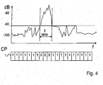
- FIG. 4 shows the sketch of a diagram of a spectrum of an IEEE 802.15.4 O-QPSK signal in the 2.4 GHz ISM frequency range as well as an associated noise source channel pattern CP. It can be seen that the signal has a bandwidth of about 3 MHz, a signal level of more than about -65 dB.
- characteristic spectra of the signal emitted by the interference source and associated binary interference source channel patterns CP can be detected for a large number of interference sources, which can be used for comparison with the bit codes of the read-out channel lists CL.
Landscapes
- Engineering & Computer Science (AREA)
- General Engineering & Computer Science (AREA)
- Manufacturing & Machinery (AREA)
- Quality & Reliability (AREA)
- Physics & Mathematics (AREA)
- General Physics & Mathematics (AREA)
- Automation & Control Theory (AREA)
- Mobile Radio Communication Systems (AREA)
- Monitoring And Testing Of Transmission In General (AREA)
- Noise Elimination (AREA)
Applications Claiming Priority (1)
| Application Number | Priority Date | Filing Date | Title |
|---|---|---|---|
| DE102007054678A DE102007054678B3 (de) | 2007-11-14 | 2007-11-14 | Verfahren zur Erkennung von Störquellen für Automatisierungseinrichtungen und Störquellenerkennungseinheit hierzu |
Publications (3)
| Publication Number | Publication Date |
|---|---|
| EP2063337A2 true EP2063337A2 (fr) | 2009-05-27 |
| EP2063337A3 EP2063337A3 (fr) | 2010-07-21 |
| EP2063337B1 EP2063337B1 (fr) | 2012-02-15 |
Family
ID=40384725
Family Applications (1)
| Application Number | Title | Priority Date | Filing Date |
|---|---|---|---|
| EP08019453A Not-in-force EP2063337B1 (fr) | 2007-11-14 | 2008-11-06 | Procédé de reconnaissance de sources de perturbation pour dispositifs d'automatisation et unité de reconnaissance de sources de perturbation correspondante |
Country Status (6)
| Country | Link |
|---|---|
| US (1) | US8331870B2 (fr) |
| EP (1) | EP2063337B1 (fr) |
| JP (1) | JP5305197B2 (fr) |
| CN (1) | CN101437237B (fr) |
| AT (1) | ATE545897T1 (fr) |
| DE (1) | DE102007054678B3 (fr) |
Families Citing this family (5)
| Publication number | Priority date | Publication date | Assignee | Title |
|---|---|---|---|---|
| JP6176629B2 (ja) * | 2013-12-03 | 2017-08-09 | インターナショナル・ビジネス・マシーンズ・コーポレーションInternational Business Machines Corporation | 特定装置、特定方法、及び、プログラム |
| CN103686793A (zh) * | 2013-12-23 | 2014-03-26 | 大唐移动通信设备有限公司 | 一种干扰源确定方法及装置 |
| CN106877947B (zh) * | 2017-01-20 | 2020-03-27 | 浙江大学 | 一种无人机的射频信道并行检测装置及方法 |
| US10816588B2 (en) * | 2018-07-12 | 2020-10-27 | Fanuc Corporation | Noise source monitoring apparatus and noise source monitoring method |
| CN111009109B (zh) * | 2019-12-26 | 2020-10-27 | 深圳市创仁科技有限公司 | M-bus接收电路和基于m-bus的4g水表采集器 |
Citations (3)
| Publication number | Priority date | Publication date | Assignee | Title |
|---|---|---|---|---|
| EP1449397B1 (fr) | 2001-11-30 | 2005-06-15 | Telefonaktiebolaget LM Ericsson (publ) | Mesures de brouillage dans un systeme de communications sans fil |
| EP1717997A1 (fr) | 2005-04-25 | 2006-11-02 | Nokia Corporation | Réduction de l'interférence mutuelle entre multiples piconets par le contrôle de l'utilisation de canal à l'aide de procédés de sauts de fréquences adaptifs |
| DE102006009979A1 (de) | 2006-03-03 | 2007-09-06 | Siemens Ag | Einrichtung zur drahtlosen Kommunikation mit einem Feldgerät |
Family Cites Families (17)
| Publication number | Priority date | Publication date | Assignee | Title |
|---|---|---|---|---|
| JPH0799482A (ja) * | 1993-04-19 | 1995-04-11 | Nippon Telegr & Teleph Corp <Ntt> | 光通信方式の判定装置および光通信装置の試験装置 |
| DE4402002B4 (de) * | 1994-01-18 | 2005-10-27 | Wago Verwaltungsgesellschaft Mbh | E/A-Module/ für einen Datenbus |
| DE19511655A1 (de) | 1995-03-30 | 1996-10-02 | Vossloh Schwabe Gmbh | Anschlußelement für elektrische Geräte |
| DE50007910D1 (de) * | 1999-04-21 | 2004-10-28 | Siemens Ag | Steuervorrichtung für stellantriebe einer brennkraftmaschine |
| DE19949387B4 (de) | 1999-10-13 | 2012-12-20 | Adels-Contact Elektrotechnische Fabrik Gmbh & Co. Kg | Kontaktteil für Anschlussklemme |
| DE20013439U1 (de) | 2000-05-05 | 2001-09-13 | Weidmüller Interface GmbH & Co, 32760 Detmold | Verbindungsklemme mit Blattklemmfeder |
| DE60119567T2 (de) * | 2000-11-16 | 2007-05-03 | Broadcom Corp., Irvine | Verfahren und vorrichtung zur erkennung und klassifikation von störungen in einem rf-modulierten netzwerk |
| US7454222B2 (en) * | 2000-11-22 | 2008-11-18 | Dragonwave, Inc. | Apparatus and method for controlling wireless communication signals |
| US7236511B2 (en) * | 2001-01-16 | 2007-06-26 | Texas Instruments Incorporated | Structured adaptive frequency hopping |
| JP4678808B2 (ja) * | 2001-03-27 | 2011-04-27 | ハイテクリサーチ株式会社 | ノイズ環境適応型無線lanシステム |
| JP4067821B2 (ja) * | 2001-12-21 | 2008-03-26 | 日立建機株式会社 | 油圧ショベルの遠隔操作システム |
| US7152025B2 (en) * | 2002-02-28 | 2006-12-19 | Texas Instruments Incorporated | Noise identification in a communication system |
| DE10350063A1 (de) * | 2003-10-27 | 2005-05-25 | Rohde & Schwarz Gmbh & Co. Kg | Verfahren und Vorrichtung zur Messung von Funkstörpegeln mit Frequenznachführung |
| FR2873859B1 (fr) | 2004-07-30 | 2006-12-08 | Legrand Sa | Appareil electrique comportant une borne a connexion automatique |
| US20060171327A1 (en) * | 2005-02-03 | 2006-08-03 | Autocell Laboratories, Inc. | Interference source recognition for wireless LANs |
| DE202005014510U1 (de) | 2005-09-14 | 2005-12-01 | Wago Verwaltungsgesellschaft Mbh | Anschlussklemme für elektrische Leiter |
| WO2007083782A1 (fr) * | 2006-01-18 | 2007-07-26 | Hitachi Kokusai Electric Inc. | Dispositif de communication |
-
2007
- 2007-11-14 DE DE102007054678A patent/DE102007054678B3/de not_active Expired - Fee Related
-
2008
- 2008-11-05 US US12/265,400 patent/US8331870B2/en not_active Expired - Fee Related
- 2008-11-06 EP EP08019453A patent/EP2063337B1/fr not_active Not-in-force
- 2008-11-06 AT AT08019453T patent/ATE545897T1/de active
- 2008-11-13 JP JP2008313718A patent/JP5305197B2/ja not_active Expired - Fee Related
- 2008-11-14 CN CN2008101842124A patent/CN101437237B/zh not_active Expired - Fee Related
Patent Citations (3)
| Publication number | Priority date | Publication date | Assignee | Title |
|---|---|---|---|---|
| EP1449397B1 (fr) | 2001-11-30 | 2005-06-15 | Telefonaktiebolaget LM Ericsson (publ) | Mesures de brouillage dans un systeme de communications sans fil |
| EP1717997A1 (fr) | 2005-04-25 | 2006-11-02 | Nokia Corporation | Réduction de l'interférence mutuelle entre multiples piconets par le contrôle de l'utilisation de canal à l'aide de procédés de sauts de fréquences adaptifs |
| DE102006009979A1 (de) | 2006-03-03 | 2007-09-06 | Siemens Ag | Einrichtung zur drahtlosen Kommunikation mit einem Feldgerät |
Also Published As
| Publication number | Publication date |
|---|---|
| CN101437237A (zh) | 2009-05-20 |
| DE102007054678B3 (de) | 2009-04-02 |
| ATE545897T1 (de) | 2012-03-15 |
| JP5305197B2 (ja) | 2013-10-02 |
| CN101437237B (zh) | 2013-04-03 |
| US20090129453A1 (en) | 2009-05-21 |
| EP2063337B1 (fr) | 2012-02-15 |
| JP2009124713A (ja) | 2009-06-04 |
| US8331870B2 (en) | 2012-12-11 |
| EP2063337A3 (fr) | 2010-07-21 |
Similar Documents
| Publication | Publication Date | Title |
|---|---|---|
| DE10147916C1 (de) | Verfahren und Übertragungseinrichtung zum Erkennen des Sendezustandes von an Energieversorgungsleitungen angeschlossenen Übertragungseinrichtungen | |
| DE10358650A1 (de) | System und Verfahren zum Identifizieren von Störungen in einem Kommunikationsspektrum | |
| EP2759814A1 (fr) | Armoire à micro-ondes et procédé de détection d'un objet dans un chemin de micro-ondes | |
| EP2063337B1 (fr) | Procédé de reconnaissance de sources de perturbation pour dispositifs d'automatisation et unité de reconnaissance de sources de perturbation correspondante | |
| DE112016004033B4 (de) | Verfahren zum Übertragen eines Signals und Sendegerät zum Senden eines Signals | |
| EP3146355B1 (fr) | Système d'appareils médicaux et procédé pour localiser des appareils médicaux et des unités de commande mobiles de ce système d'appareils médicaux | |
| EP3269184B1 (fr) | Dispositif et procédé d'adaptation de puissance d'un réseau wlan | |
| DE102013219083A1 (de) | Verfahren zur Frequenzzuweisung eines drahtlosen Funk-Audioübertragungssystems sowie drahtloses Funk-Audioübertragungssystem | |
| EP2136582B1 (fr) | Procédé et système informatique de planification de champ RF | |
| EP3357283B1 (fr) | Procédé et dispositif pour améliorer la qualité de signal d'au moins un service de communication dans la zone d'un véhicule | |
| DE102014211237A1 (de) | Verfahren und System zum Erfassen mindestens eines Zustands eines Raums | |
| EP3282740B1 (fr) | Dispositif de surveillance de bande pour un système de radiocommunication | |
| DE102010032369B4 (de) | Anmeldeverfahren für Funkkommunikationssysteme | |
| DE10004421A1 (de) | Funk-Identifikationssystem und -verfahren | |
| EP1681581B1 (fr) | Système de mesure de distance pour déterminer une zone de distances | |
| DE10359898A1 (de) | Verfahren zum Steuern und Überwachen von Maschinen | |
| EP2362553B1 (fr) | Procédé de détermination d'un canal d'émission pour un système RFID | |
| DE102008047212A1 (de) | Verfahren zur rechnergestützten Lokalisation eines mobilen Objekts | |
| WO2013013706A1 (fr) | Procédé d'échange sans fil de données ainsi qu'appareil d'accès pour accéder à une mémoire de données | |
| EP2381389B1 (fr) | Procédé de fonctionnement simultané d'une station d'écriture/lecture d'un système RFID et d'un système en duplex de fréquence | |
| DE102007014997B4 (de) | Redundante Signalübertragung | |
| EP1648191A2 (fr) | Dispositif de transmission de données de consommation à l'aide d'un système de communication à bande ultra-large | |
| DE102022109948A1 (de) | Batteriebetriebener Schwingungssensor für die Automatisierungstechnik | |
| EP3357298B1 (fr) | Procédé et dispositif pour améliorer la qualité de signal d'au moins un service de communication dans la zone d'une unité émettrice mobile | |
| DE102015211825A1 (de) | Verfahren und System zum Prüfen der Authentizität empfangener Daten |
Legal Events
| Date | Code | Title | Description |
|---|---|---|---|
| PUAI | Public reference made under article 153(3) epc to a published international application that has entered the european phase |
Free format text: ORIGINAL CODE: 0009012 |
|
| AK | Designated contracting states |
Kind code of ref document: A2 Designated state(s): AT BE BG CH CY CZ DE DK EE ES FI FR GB GR HR HU IE IS IT LI LT LU LV MC MT NL NO PL PT RO SE SI SK TR |
|
| AX | Request for extension of the european patent |
Extension state: AL BA MK RS |
|
| PUAL | Search report despatched |
Free format text: ORIGINAL CODE: 0009013 |
|
| AK | Designated contracting states |
Kind code of ref document: A3 Designated state(s): AT BE BG CH CY CZ DE DK EE ES FI FR GB GR HR HU IE IS IT LI LT LU LV MC MT NL NO PL PT RO SE SI SK TR |
|
| AX | Request for extension of the european patent |
Extension state: AL BA MK RS |
|
| RIC1 | Information provided on ipc code assigned before grant |
Ipc: H04W 16/14 20090101ALI20100617BHEP Ipc: G05B 19/418 20060101AFI20090401BHEP |
|
| 17P | Request for examination filed |
Effective date: 20100804 |
|
| AKX | Designation fees paid |
Designated state(s): AT BE BG CH CY CZ DE DK EE ES FI FR GB GR HR HU IE IS IT LI LT LU LV MC MT NL NO PL PT RO SE SI SK TR |
|
| GRAP | Despatch of communication of intention to grant a patent |
Free format text: ORIGINAL CODE: EPIDOSNIGR1 |
|
| RIC1 | Information provided on ipc code assigned before grant |
Ipc: H04W 16/14 20090101ALI20110725BHEP Ipc: G05B 19/418 20060101AFI20110725BHEP |
|
| GRAS | Grant fee paid |
Free format text: ORIGINAL CODE: EPIDOSNIGR3 |
|
| GRAA | (expected) grant |
Free format text: ORIGINAL CODE: 0009210 |
|
| AK | Designated contracting states |
Kind code of ref document: B1 Designated state(s): AT BE BG CH CY CZ DE DK EE ES FI FR GB GR HR HU IE IS IT LI LT LU LV MC MT NL NO PL PT RO SE SI SK TR |
|
| REG | Reference to a national code |
Ref country code: CH Ref legal event code: EP Ref country code: GB Ref legal event code: FG4D Free format text: NOT ENGLISH |
|
| REG | Reference to a national code |
Ref country code: IE Ref legal event code: FG4D Free format text: LANGUAGE OF EP DOCUMENT: GERMAN |
|
| REG | Reference to a national code |
Ref country code: AT Ref legal event code: REF Ref document number: 545897 Country of ref document: AT Kind code of ref document: T Effective date: 20120315 |
|
| REG | Reference to a national code |
Ref country code: CH Ref legal event code: NV Representative=s name: BOHEST AG |
|
| REG | Reference to a national code |
Ref country code: DE Ref legal event code: R096 Ref document number: 502008006392 Country of ref document: DE Effective date: 20120412 |
|
| REG | Reference to a national code |
Ref country code: NL Ref legal event code: VDEP Effective date: 20120215 |
|
| LTIE | Lt: invalidation of european patent or patent extension |
Effective date: 20120215 |
|
| PG25 | Lapsed in a contracting state [announced via postgrant information from national office to epo] |
Ref country code: LT Free format text: LAPSE BECAUSE OF FAILURE TO SUBMIT A TRANSLATION OF THE DESCRIPTION OR TO PAY THE FEE WITHIN THE PRESCRIBED TIME-LIMIT Effective date: 20120215 Ref country code: HR Free format text: LAPSE BECAUSE OF FAILURE TO SUBMIT A TRANSLATION OF THE DESCRIPTION OR TO PAY THE FEE WITHIN THE PRESCRIBED TIME-LIMIT Effective date: 20120215 Ref country code: NL Free format text: LAPSE BECAUSE OF FAILURE TO SUBMIT A TRANSLATION OF THE DESCRIPTION OR TO PAY THE FEE WITHIN THE PRESCRIBED TIME-LIMIT Effective date: 20120215 Ref country code: NO Free format text: LAPSE BECAUSE OF FAILURE TO SUBMIT A TRANSLATION OF THE DESCRIPTION OR TO PAY THE FEE WITHIN THE PRESCRIBED TIME-LIMIT Effective date: 20120515 Ref country code: IS Free format text: LAPSE BECAUSE OF FAILURE TO SUBMIT A TRANSLATION OF THE DESCRIPTION OR TO PAY THE FEE WITHIN THE PRESCRIBED TIME-LIMIT Effective date: 20120615 |
|
| PG25 | Lapsed in a contracting state [announced via postgrant information from national office to epo] |
Ref country code: PT Free format text: LAPSE BECAUSE OF FAILURE TO SUBMIT A TRANSLATION OF THE DESCRIPTION OR TO PAY THE FEE WITHIN THE PRESCRIBED TIME-LIMIT Effective date: 20120615 Ref country code: GR Free format text: LAPSE BECAUSE OF FAILURE TO SUBMIT A TRANSLATION OF THE DESCRIPTION OR TO PAY THE FEE WITHIN THE PRESCRIBED TIME-LIMIT Effective date: 20120516 Ref country code: LV Free format text: LAPSE BECAUSE OF FAILURE TO SUBMIT A TRANSLATION OF THE DESCRIPTION OR TO PAY THE FEE WITHIN THE PRESCRIBED TIME-LIMIT Effective date: 20120215 Ref country code: FI Free format text: LAPSE BECAUSE OF FAILURE TO SUBMIT A TRANSLATION OF THE DESCRIPTION OR TO PAY THE FEE WITHIN THE PRESCRIBED TIME-LIMIT Effective date: 20120215 Ref country code: PL Free format text: LAPSE BECAUSE OF FAILURE TO SUBMIT A TRANSLATION OF THE DESCRIPTION OR TO PAY THE FEE WITHIN THE PRESCRIBED TIME-LIMIT Effective date: 20120215 |
|
| REG | Reference to a national code |
Ref country code: IE Ref legal event code: FD4D |
|
| PG25 | Lapsed in a contracting state [announced via postgrant information from national office to epo] |
Ref country code: CY Free format text: LAPSE BECAUSE OF FAILURE TO SUBMIT A TRANSLATION OF THE DESCRIPTION OR TO PAY THE FEE WITHIN THE PRESCRIBED TIME-LIMIT Effective date: 20120215 |
|
| PG25 | Lapsed in a contracting state [announced via postgrant information from national office to epo] |
Ref country code: CZ Free format text: LAPSE BECAUSE OF FAILURE TO SUBMIT A TRANSLATION OF THE DESCRIPTION OR TO PAY THE FEE WITHIN THE PRESCRIBED TIME-LIMIT Effective date: 20120215 Ref country code: SE Free format text: LAPSE BECAUSE OF FAILURE TO SUBMIT A TRANSLATION OF THE DESCRIPTION OR TO PAY THE FEE WITHIN THE PRESCRIBED TIME-LIMIT Effective date: 20120215 Ref country code: RO Free format text: LAPSE BECAUSE OF FAILURE TO SUBMIT A TRANSLATION OF THE DESCRIPTION OR TO PAY THE FEE WITHIN THE PRESCRIBED TIME-LIMIT Effective date: 20120215 Ref country code: SI Free format text: LAPSE BECAUSE OF FAILURE TO SUBMIT A TRANSLATION OF THE DESCRIPTION OR TO PAY THE FEE WITHIN THE PRESCRIBED TIME-LIMIT Effective date: 20120215 Ref country code: EE Free format text: LAPSE BECAUSE OF FAILURE TO SUBMIT A TRANSLATION OF THE DESCRIPTION OR TO PAY THE FEE WITHIN THE PRESCRIBED TIME-LIMIT Effective date: 20120215 Ref country code: DK Free format text: LAPSE BECAUSE OF FAILURE TO SUBMIT A TRANSLATION OF THE DESCRIPTION OR TO PAY THE FEE WITHIN THE PRESCRIBED TIME-LIMIT Effective date: 20120215 Ref country code: IE Free format text: LAPSE BECAUSE OF FAILURE TO SUBMIT A TRANSLATION OF THE DESCRIPTION OR TO PAY THE FEE WITHIN THE PRESCRIBED TIME-LIMIT Effective date: 20120215 |
|
| PG25 | Lapsed in a contracting state [announced via postgrant information from national office to epo] |
Ref country code: SK Free format text: LAPSE BECAUSE OF FAILURE TO SUBMIT A TRANSLATION OF THE DESCRIPTION OR TO PAY THE FEE WITHIN THE PRESCRIBED TIME-LIMIT Effective date: 20120215 |
|
| PLBE | No opposition filed within time limit |
Free format text: ORIGINAL CODE: 0009261 |
|
| STAA | Information on the status of an ep patent application or granted ep patent |
Free format text: STATUS: NO OPPOSITION FILED WITHIN TIME LIMIT |
|
| 26N | No opposition filed |
Effective date: 20121116 |
|
| REG | Reference to a national code |
Ref country code: DE Ref legal event code: R097 Ref document number: 502008006392 Country of ref document: DE Effective date: 20121116 |
|
| PG25 | Lapsed in a contracting state [announced via postgrant information from national office to epo] |
Ref country code: ES Free format text: LAPSE BECAUSE OF FAILURE TO SUBMIT A TRANSLATION OF THE DESCRIPTION OR TO PAY THE FEE WITHIN THE PRESCRIBED TIME-LIMIT Effective date: 20120526 |
|
| BERE | Be: lapsed |
Owner name: WAGO VERWALTUNGSGESELLSCHAFT MBH Effective date: 20121130 |
|
| GBPC | Gb: european patent ceased through non-payment of renewal fee |
Effective date: 20121106 |
|
| PG25 | Lapsed in a contracting state [announced via postgrant information from national office to epo] |
Ref country code: BG Free format text: LAPSE BECAUSE OF FAILURE TO SUBMIT A TRANSLATION OF THE DESCRIPTION OR TO PAY THE FEE WITHIN THE PRESCRIBED TIME-LIMIT Effective date: 20120515 |
|
| PG25 | Lapsed in a contracting state [announced via postgrant information from national office to epo] |
Ref country code: BE Free format text: LAPSE BECAUSE OF NON-PAYMENT OF DUE FEES Effective date: 20121130 |
|
| PG25 | Lapsed in a contracting state [announced via postgrant information from national office to epo] |
Ref country code: MT Free format text: LAPSE BECAUSE OF FAILURE TO SUBMIT A TRANSLATION OF THE DESCRIPTION OR TO PAY THE FEE WITHIN THE PRESCRIBED TIME-LIMIT Effective date: 20120215 Ref country code: GB Free format text: LAPSE BECAUSE OF NON-PAYMENT OF DUE FEES Effective date: 20121106 |
|
| REG | Reference to a national code |
Ref country code: DE Ref legal event code: R082 Ref document number: 502008006392 Country of ref document: DE Representative=s name: BARDEHLE PAGENBERG PARTNERSCHAFT MBB PATENTANW, DE |
|
| PG25 | Lapsed in a contracting state [announced via postgrant information from national office to epo] |
Ref country code: MC Free format text: LAPSE BECAUSE OF NON-PAYMENT OF DUE FEES Effective date: 20121130 Ref country code: TR Free format text: LAPSE BECAUSE OF FAILURE TO SUBMIT A TRANSLATION OF THE DESCRIPTION OR TO PAY THE FEE WITHIN THE PRESCRIBED TIME-LIMIT Effective date: 20120215 |
|
| PG25 | Lapsed in a contracting state [announced via postgrant information from national office to epo] |
Ref country code: LU Free format text: LAPSE BECAUSE OF NON-PAYMENT OF DUE FEES Effective date: 20121106 |
|
| REG | Reference to a national code |
Ref country code: CH Ref legal event code: PCAR Free format text: NEW ADDRESS: HOLBEINSTRASSE 36-38, 4051 BASEL (CH) |
|
| PG25 | Lapsed in a contracting state [announced via postgrant information from national office to epo] |
Ref country code: HU Free format text: LAPSE BECAUSE OF FAILURE TO SUBMIT A TRANSLATION OF THE DESCRIPTION OR TO PAY THE FEE WITHIN THE PRESCRIBED TIME-LIMIT Effective date: 20081106 |
|
| REG | Reference to a national code |
Ref country code: AT Ref legal event code: MM01 Ref document number: 545897 Country of ref document: AT Kind code of ref document: T Effective date: 20131106 |
|
| PG25 | Lapsed in a contracting state [announced via postgrant information from national office to epo] |
Ref country code: AT Free format text: LAPSE BECAUSE OF NON-PAYMENT OF DUE FEES Effective date: 20131106 |
|
| REG | Reference to a national code |
Ref country code: FR Ref legal event code: PLFP Year of fee payment: 8 |
|
| PGFP | Annual fee paid to national office [announced via postgrant information from national office to epo] |
Ref country code: CH Payment date: 20151123 Year of fee payment: 8 Ref country code: IT Payment date: 20151124 Year of fee payment: 8 |
|
| PGFP | Annual fee paid to national office [announced via postgrant information from national office to epo] |
Ref country code: FR Payment date: 20151124 Year of fee payment: 8 |
|
| REG | Reference to a national code |
Ref country code: CH Ref legal event code: PL |
|
| PG25 | Lapsed in a contracting state [announced via postgrant information from national office to epo] |
Ref country code: CH Free format text: LAPSE BECAUSE OF NON-PAYMENT OF DUE FEES Effective date: 20161130 Ref country code: LI Free format text: LAPSE BECAUSE OF NON-PAYMENT OF DUE FEES Effective date: 20161130 |
|
| REG | Reference to a national code |
Ref country code: FR Ref legal event code: ST Effective date: 20170731 |
|
| PG25 | Lapsed in a contracting state [announced via postgrant information from national office to epo] |
Ref country code: FR Free format text: LAPSE BECAUSE OF NON-PAYMENT OF DUE FEES Effective date: 20161130 Ref country code: IT Free format text: LAPSE BECAUSE OF NON-PAYMENT OF DUE FEES Effective date: 20161106 |
|
| PGFP | Annual fee paid to national office [announced via postgrant information from national office to epo] |
Ref country code: DE Payment date: 20190131 Year of fee payment: 11 |
|
| REG | Reference to a national code |
Ref country code: DE Ref legal event code: R119 Ref document number: 502008006392 Country of ref document: DE |
|
| PG25 | Lapsed in a contracting state [announced via postgrant information from national office to epo] |
Ref country code: DE Free format text: LAPSE BECAUSE OF NON-PAYMENT OF DUE FEES Effective date: 20200603 |