EP2063665A2 - Appareil auditif doté d'un dispositif de commande - Google Patents
Appareil auditif doté d'un dispositif de commande Download PDFInfo
- Publication number
- EP2063665A2 EP2063665A2 EP08166732A EP08166732A EP2063665A2 EP 2063665 A2 EP2063665 A2 EP 2063665A2 EP 08166732 A EP08166732 A EP 08166732A EP 08166732 A EP08166732 A EP 08166732A EP 2063665 A2 EP2063665 A2 EP 2063665A2
- Authority
- EP
- European Patent Office
- Prior art keywords
- operating
- operating function
- activation
- function
- hearing aid
- Prior art date
- Legal status (The legal status is an assumption and is not a legal conclusion. Google has not performed a legal analysis and makes no representation as to the accuracy of the status listed.)
- Withdrawn
Links
Images
Classifications
-
- H—ELECTRICITY
- H04—ELECTRIC COMMUNICATION TECHNIQUE
- H04R—LOUDSPEAKERS, MICROPHONES, GRAMOPHONE PICK-UPS OR LIKE ACOUSTIC ELECTROMECHANICAL TRANSDUCERS; ELECTRIC HEARING AIDS; PUBLIC ADDRESS SYSTEMS
- H04R25/00—Electric hearing aids
-
- H—ELECTRICITY
- H01—ELECTRIC ELEMENTS
- H01H—ELECTRIC SWITCHES; RELAYS; SELECTORS; EMERGENCY PROTECTIVE DEVICES
- H01H25/00—Switches with compound movement of handle or other operating part
- H01H25/06—Operating part movable both angularly and rectilinearly, the rectilinear movement being along the axis of angular movement
-
- H—ELECTRICITY
- H01—ELECTRIC ELEMENTS
- H01H—ELECTRIC SWITCHES; RELAYS; SELECTORS; EMERGENCY PROTECTIVE DEVICES
- H01H2300/00—Orthogonal indexing scheme relating to electric switches, relays, selectors or emergency protective devices covered by H01H
- H01H2300/004—Application hearing aid
-
- H—ELECTRICITY
- H04—ELECTRIC COMMUNICATION TECHNIQUE
- H04R—LOUDSPEAKERS, MICROPHONES, GRAMOPHONE PICK-UPS OR LIKE ACOUSTIC ELECTROMECHANICAL TRANSDUCERS; ELECTRIC HEARING AIDS; PUBLIC ADDRESS SYSTEMS
- H04R2225/00—Details of deaf aids covered by H04R25/00, not provided for in any of its subgroups
- H04R2225/61—Aspects relating to mechanical or electronic switches or control elements, e.g. functioning
-
- H—ELECTRICITY
- H04—ELECTRIC COMMUNICATION TECHNIQUE
- H04R—LOUDSPEAKERS, MICROPHONES, GRAMOPHONE PICK-UPS OR LIKE ACOUSTIC ELECTROMECHANICAL TRANSDUCERS; ELECTRIC HEARING AIDS; PUBLIC ADDRESS SYSTEMS
- H04R25/00—Electric hearing aids
- H04R25/60—Mounting or interconnection of hearing aid parts, e.g. inside tips, housings or to ossicles
- H04R25/603—Mounting or interconnection of hearing aid parts, e.g. inside tips, housings or to ossicles of mechanical or electronic switches or control elements
Definitions
- the invention relates to a hearing aid with an operating device, wherein a first and a second operating function of the hearing aid can be activated via an operating element of the operating device. It is provided to suppress the execution of the first operating function, if the second operating function is activated via the operating element. Furthermore, the invention relates to a corresponding method for operating a hearing aid.
- Modern hearing aids have a variety of different settings, such. B. those for electrical or acoustic parameters. While certain parameters of a hearing aid are set, for example, by an acoustician during a programming session, other settings during operation of the hearing aid can be made independently by the hearing aid wearer. Among the latter settings include z. As the volume setting, the change between different hearing programs or operating modes or switching on and off of the hearing aid. Such adjustments are typically made via controls that are typically located well accessible on the outside of the device. With such controls different degrees of freedom of the control can be exploited. Thus, in an appropriately designed control element in addition to the simple operation of a push-button or z. B. also use a variety of turning, tilting, rocking or sliding movements to activate the device functions.
- Such controls then include, for example, two different input devices, such as a mechanical push button and a rotary switch. Also other combinations of input devices, such as e.g. a pressure switch and a toggle or rocker switch or a pressure switch or pushbutton switch and a slide switch, can be realized in a control element.
- operating functions can also be clearly recognized due to the duration of the manual input and thus distinguished from each other. So can be z.
- various operating functions differ from each other as long as the push-button is operated manually.
- a hearing device has an operating device, which comprises an operating element for activating a first and a second operating function of the hearing device.
- the operating device is designed to perform an operating function of the hearing aid due to or as a result of activation of the corresponding operating function via the operating element.
- the operating device is designed to prevent the execution of the first operating function due to or as a result of the activation of the first operating function via the operating element, provided that the second operating function is activated via the operating element.
- the activation of the first operating function via the control element thus does not directly lead to an execution of this operating function in the hearing aid. Rather, the execution of the first operating function is controlled depending on whether the second operating function has been activated via the common operating element.
- this can effectively prevent inadvertent execution of the first operating function in an intended activation of the second operating function.
- the operating device deletes a first activation signal, which is generated when the first operating function is activated, if the second operating function is activated via the operating element. Deleting the first activation signal resets the activation of the first operating function. Thus, the execution of this operating function can be effectively prevented.
- a further advantageous embodiment of the invention provides that a control device is provided with a logic circuit, wherein the logic circuit serves as input variables the first activation signal generated by the activation of the first operating function and a second activation signal generated by the activation of the second operating function. It is provided that the logic circuit executes the corresponding operating function in the presence of an activation signal, wherein the logic circuit resets the first activation signal, provided that the second activation signal is present at its input.
- the logic circuitry makes it particularly easy to control the operating functions.
- a designed as an electrical circuit logic circuit can be realized particularly easily and inexpensively by logic gates.
- a mechanical control device in which the execution of the first operating function can be blocked by the activation of the second operating function.
- the operating element comprises a push-button or push-button switch, the activation of the first operating function being effected by actuating this switch. It is advantageous if the first operating function is activated only when you release the key switch. In this case, the time between unintentional pressing and releasing the push-button switch can be used for checking whether the second operating function has been activated. If this is the case, the first operating function is not executed. Already using this simple method, unintentional operator actions can be effectively avoided.
- activating the second operating function is done by pressing a rotary or toggle switch comprehensive control.
- a rotary or toggle switch comprehensive control Just by combining such a switch with a push-button switch, multifunctional operating elements can be realized in a particularly small space.
- a further advantageous embodiment of the invention provides that the operating device executes the first operating function delayed after activation of the first operating function via the operating element. This delay makes it possible to detect such activations of the second operating function via the operating element, which are only after the activation of the first operating function.
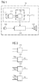
- the z. B. may be formed as an ITE hearing aid.
- an electrical signal provided by an input microphone 140 is processed by a signal processor 141 in accordance with a specification.
- an output converter 142 is driven via an output stage, which generates a corresponding sound signal in the auditory canal of the hearing device wearer.
- the components 140, 141, 142 of the signal processing path are shown by way of example only, with not all components shown.
- a typical hearing aid 100 has various settings, the z. B. concern the signal processing or the operation of the device as such. Depending on the application, certain parameters may already be preset during manufacture or a subsequent configuration. Other settings, such as As the selection of the operating mode, can also be made independently by the hearing aid wearer.
- the various setting options are implemented as operating functions in the hearing device 100, which are called via an operating device 110 of the hearing aid 100.
- the operating device 110 has at least one operating element 111 that is accessible to the hearing aid wearer, via which an operating function can be selected or activated.
- the operating element 111 is designed as a multifunctional operating element, via which at least two different operating functions can be activated independently of one another.
- the operating element 111 can be designed as a mechanical operating element. As a rule, such an operating element must be mechanically actuated in a manner predetermined by its design in order to activate a specific operating function. In order to clearly determine the input or activation of an operating function via the operating element, the various operating functions of the respective operating element are generally associated with different movement sequences. Thus, in a hearing aid frequently the two operating functions volume adjustment (volume control, VC) and program change (push button, PB) can be activated via a common control element 111, wherein the change of programs or operating modes z. B. can be selected via a push-button and the volume control via a rotary switch. The switches are combined in the common control element 111.
- volume control volume control
- PB program change
- switch combinations such as a touch or push switch and a tilt, rocker or slide switch can also be used.
- a touch or push switch and a tilt, rocker or slide switch can also be used.
- such have multifunctional controls and non-mechanical input devices in which the activation of the respective operating function z. B. takes place only by touching a correspondingly sensitive surface or by approaching such a surface.
- the operating device 110 also includes a control device 130.
- the control device 130 controls the execution of the operating functions which are activated via the common operating element 111
- the control device 130 as in the present case, a logic circuit 131 include.
- the activation signals S PB , S vc can receive the logic circuit 131 via corresponding signal lines from the operating element 110.
- the logic circuit 131 or the control device 130 controls the execution of the respective operating function PB, VC by means of a corresponding control signal.
- the logic circuit 131 can output the control signal to the component in which the corresponding operating function is executed.
- the logic circuit 131 is connected to the signal processing device 141 via a signal line.
- Both the logic circuit 131 and the controller 130 may be formed as integrated circuits. In such a case, the logic circuit 131 or the entire control device 130 may be accommodated together with the signal processing device 141 or with parts thereof on a chip.
- control device 130 shown here is preferably implemented electronically, it is basically also possible to control the activation via the operating element 111 Operating functions PB, VC mechanically realized.
- the connecting arrows between the components 110, 131, 141 would constitute mechanical active connections.
- the execution of the first operating function PB could then be prevented by a mechanical blocking of the corresponding operative connection.
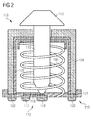
- control element 111 will be described in more detail, which is particularly well suited for use in an ITE hearing aid because of its small footprint.
- FIG. 2 shows by way of example such a multifunctional operating element 111 in a cross-sectional representation.
- the control element 111 in this case comprises a push-button switch 112 and a rotary switch 113. Both switches 112, 113 are actuated by means of a common actuating button 114.
- the key switch 112 consists essentially of a first and a second contact element 117, 119, wherein a contact arm 118 connected to the first contact element 117 is arranged resiliently over the second contact element 119.
- the closing of the key switch 112 is carried out by the operating button 114 is pressed against the spring force of the spring element 116 downward. With its tip, a switching pin 115 connected to the actuating button 114 then presses the contact arm 118 against the second contact 119 in such a way that a circuit is closed via the push-button switch 112.
- the actuating button 114 is released, it is raised again by the spring element 116, so that the contact arm 118 swings upward again.
- the switching contact is interrupted and the key switch 112 is opened again.
- a reverse switching behavior in which the switching contact when depressing the actuating button 114 is opened and closed when you release the actuator button 114 is possible in principle.
- the push-button function PB of the hearing aid 100 is activated only when the actuation button 114 is released.
- the corresponding activation signal S PB is therefore generated in the negative example in the present example, ie only when the key switch 112 is opened.
- the second operating function of the hearing aid 100 is activated in the present case by means of the rotary switch 113 of the operating element 111.
- the rotary switch 113 has a one or more rotationally symmetrical about the switching pin 115 disposed contact pads 121.
- a sleeve-shaped element 120 which is arranged within a sleeve-shaped housing 124 of the actuating element 110, serves as a rotor. The rotor 120 is thereby rotated by the switching pin 115.
- the current switching state can be z. B. by current or voltage measurement via corresponding contacts 122, 123 are determined. It determines the current volume setting of the hearing aid 100.
- the execution of the first operating function PB (change of operating mode or program) already takes place in case of accidental depression of the operating button 114, before the actual intended rotation of the actuating button 114 and the associated activation of the second operating function VC was detected takes place the execution of the first operating function PB preferably not directly by the activation of this operating function on the control element 111. Rather, a certain delay between the activation and the execution of the first operating function PB is provided. If the hearing device 100 or its control device 130 detects in this time that the second operating function VC has been activated by a corresponding actuation of the operating element 111, the execution of the first operating function PB is suppressed.
- the activation of the second operating function VC can also be used for deleting the first activation signal S PB or more generally for resetting the activation state of the first operating function PB. Also in this case, only the second activated operating function VC is executed.
- a delay in that in the FIG. 2 The operating element shown can be achieved, for example, by the fact that the first operating function PB is not activated, as usual, when the push-button 112 is depressed, but only in the negative pulse, that is to say when the push-button 112 is released. This can be achieved relatively easily by an appropriate electronics, which triggers only on the signal edge generated when you release the key switch. Since the time between the depression and the release of the key switch 112 depends strongly on the individual user behavior of the user, additional measures can be provided to obtain a necessary for a fault-free detection of the operation intention delay time.
- the operating device 110 may be designed such that the first operating function PB is not executed immediately after the activation of the corresponding operating function PB already delayed by triggering on the negative pulse, but only after a preferably predeterminable time has elapsed after the key switch 112 has been released ,
- a further, defined delay between activating and executing the first operating function PB can also be implemented electronically in this case.
- a logic circuit 131 which controls the execution of the operating functions PB, VC is explained by means of a table.
- Such a logic circuit can, for example, in the in the in the FIG. 2 implemented operating device 110 may be implemented. It shows the first column of the table, the activation state of the first operating function (here program change PB), which is activated by pressing or releasing the push-button. In the second column, however, the activation state of the second operating function (here volume control VC) is shown, which is activated by the rotation of the operating knob 114 of the control element 111.
- the activated state of an operating function is represented by a plus (+) and the non-active or deactivated state of the corresponding operating function by a minus (-).
- S PB corresponding activation signal
- S VC is generated by activating an operating function PB, VC
- the plus (+) and the minus (-) in the table represents the presence or absence of the respective activation signal at the corresponding input of the logic circuit 131 is.
- the third column shows which control or control function the logic circuit 131 outputs in response to the activation signals applied to its input.
- the control function determines which of the two operating functions VC or PB is actually executed or whether an operating function is to be executed at all.
- PB function VC function Control function - - - + - PB - + VC + + VC
- a signal is present only at the first of the two inputs of the logic circuit 131, namely the first activation signal S PB .
- the logic circuit 131 outputs a control signal for executing the first operation function PB at its output.
- This signal causes the hearing device or the signal processing device 141 of the hearing aid 100 to change the hearing program or the operating mode.
- only this operation function VC is executed.
- both operating functions PB, VC are activated simultaneously, so that at the logic circuit 131, the two activation signals S PB , S VC at the same time, the logic circuit 131 outputs only the signal for executing the second operation function VC.
- the execution of the first operating function PB is suppressed according to the invention.
- the two operating functions PB, VC are activated in quick succession via the control element 111.
- the invention is not limited to the embodiments shown in the figures and the description above. Rather, it extends to any controls and operating functions of a hearing aid. So z. B. also be provided with more than two operating functions, in which the execution of one or more operating functions by activating a priority operating function is prevented.
- the operating device 110 or the control device 130 or its logic circuit 131 performs an operating function PB, VC directly or whether they perform the execution of the corresponding operating function PB, VC z. B. caused by the output of a corresponding signal only.
Landscapes
- Health & Medical Sciences (AREA)
- General Health & Medical Sciences (AREA)
- Neurosurgery (AREA)
- Otolaryngology (AREA)
- Physics & Mathematics (AREA)
- Engineering & Computer Science (AREA)
- Acoustics & Sound (AREA)
- Signal Processing (AREA)
- Switches With Compound Operations (AREA)
- Input From Keyboards Or The Like (AREA)
- Selective Calling Equipment (AREA)
Applications Claiming Priority (1)
| Application Number | Priority Date | Filing Date | Title |
|---|---|---|---|
| DE102007055672A DE102007055672A1 (de) | 2007-11-21 | 2007-11-21 | Hörgerät mit einer Bedieneinrichtung |
Publications (2)
| Publication Number | Publication Date |
|---|---|
| EP2063665A2 true EP2063665A2 (fr) | 2009-05-27 |
| EP2063665A3 EP2063665A3 (fr) | 2014-05-07 |
Family
ID=40351963
Family Applications (1)
| Application Number | Title | Priority Date | Filing Date |
|---|---|---|---|
| EP08166732.1A Withdrawn EP2063665A3 (fr) | 2007-11-21 | 2008-10-16 | Appareil auditif doté d'un dispositif de commande |
Country Status (3)
| Country | Link |
|---|---|
| US (1) | US8284969B2 (fr) |
| EP (1) | EP2063665A3 (fr) |
| DE (1) | DE102007055672A1 (fr) |
Cited By (3)
| Publication number | Priority date | Publication date | Assignee | Title |
|---|---|---|---|---|
| EP1945001A3 (fr) * | 2007-01-12 | 2011-03-09 | Siemens Hearing Instruments, Inc. | Prothèse auditive avec contrôle acoustique multifonction |
| US20220279263A1 (en) * | 2021-02-26 | 2022-09-01 | Apple Inc. | Wireless listening device |
| US12160698B2 (en) | 2021-09-22 | 2024-12-03 | Apple Inc. | Audio device with wingtip anchor |
Families Citing this family (6)
| Publication number | Priority date | Publication date | Assignee | Title |
|---|---|---|---|---|
| EP2489204B1 (fr) | 2009-10-15 | 2013-11-20 | Phonak AG | Système d'écoute avec élément de commande analogique |
| US8582791B2 (en) * | 2010-04-13 | 2013-11-12 | Audiotoniq, Inc. | Hearing aid and circuit for detecting a connector |
| US8520874B1 (en) | 2011-07-26 | 2013-08-27 | Gary Beutler | Hearing aid with an operational based switch |
| US9236203B2 (en) * | 2013-08-13 | 2016-01-12 | Audina Hearing Instruments Inc. | Pushbutton pullstring adapter for hearing aid |
| US20200075272A1 (en) * | 2018-08-29 | 2020-03-05 | Soniphi Llc | Earbud With Rotary Switch |
| EP3771202B1 (fr) * | 2019-07-23 | 2023-08-30 | Top Victory Investments Limited | Procédé et système de commande automatique de sortie audio d'un dispositif de télévision sur la base du bruit ambiant |
Family Cites Families (7)
| Publication number | Priority date | Publication date | Assignee | Title |
|---|---|---|---|---|
| NL1016684C2 (nl) * | 2000-11-22 | 2002-05-23 | Beltone Netherlands B V | Hoorapparaat. |
| US20030094353A1 (en) * | 2001-10-10 | 2003-05-22 | Soren Ravnkilde | Multifunctional switch |
| US7106875B2 (en) * | 2003-09-09 | 2006-09-12 | King James T | Dual boundary pressure zone three dimensional microphone and hearing aid |
| DE502004011569D1 (de) * | 2004-04-13 | 2010-10-07 | Phonak Ag | Bedienelement für Hörgeräte und Hörhilfen |
| DE102004019353B3 (de) * | 2004-04-21 | 2005-09-15 | Siemens Audiologische Technik Gmbh | Hörhilfegerät mit einer Bedieneinrichtung |
| DE102004054927A1 (de) * | 2004-11-13 | 2006-06-01 | Hansaton Akustik Gmbh | Hörgerät mit Lautstärkestellrad |
| US20060171550A1 (en) * | 2006-03-17 | 2006-08-03 | Audina Hearing Instruments, Inc. | BTE hearing aid component and hearing aid comprising same |
-
2007
- 2007-11-21 DE DE102007055672A patent/DE102007055672A1/de not_active Withdrawn
-
2008
- 2008-10-16 EP EP08166732.1A patent/EP2063665A3/fr not_active Withdrawn
- 2008-11-21 US US12/275,505 patent/US8284969B2/en active Active
Non-Patent Citations (1)
| Title |
|---|
| None * |
Cited By (4)
| Publication number | Priority date | Publication date | Assignee | Title |
|---|---|---|---|---|
| EP1945001A3 (fr) * | 2007-01-12 | 2011-03-09 | Siemens Hearing Instruments, Inc. | Prothèse auditive avec contrôle acoustique multifonction |
| US20220279263A1 (en) * | 2021-02-26 | 2022-09-01 | Apple Inc. | Wireless listening device |
| US11606637B2 (en) * | 2021-02-26 | 2023-03-14 | Apple Inc. | Wireless listening device |
| US12160698B2 (en) | 2021-09-22 | 2024-12-03 | Apple Inc. | Audio device with wingtip anchor |
Also Published As
| Publication number | Publication date |
|---|---|
| US20090129618A1 (en) | 2009-05-21 |
| DE102007055672A1 (de) | 2009-05-28 |
| US8284969B2 (en) | 2012-10-09 |
| EP2063665A3 (fr) | 2014-05-07 |
Similar Documents
| Publication | Publication Date | Title |
|---|---|---|
| EP2063665A2 (fr) | Appareil auditif doté d'un dispositif de commande | |
| EP1589784B1 (fr) | Prothèse auditive avec dispositif de commande | |
| DE69408418T2 (de) | Hebelschaltervorrichtung, Verfahren zur Steuerung von Schaltern in solcher Vorrichtung und Verfahren zum Ausgeben von Datensignalen | |
| EP1736354B1 (fr) | Organe de commande à détecteur de proximité | |
| EP0557847A1 (fr) | Appareils portatif à tête pour sourds | |
| DE29905172U1 (de) | Handprogrammer | |
| WO2010112150A1 (fr) | Circuit modulaire de commutation de puissances électriques et adaptateur associé | |
| EP2095384B1 (fr) | Élément de commutation pour déclencher l'application d'une grandeur de réglage | |
| DE10196251B3 (de) | Unterdrückung unzulässiger Tastatureingaben während des Einschaltvorgangs | |
| DE10163194A1 (de) | Elektromechanische Stufenschaltvorrichtung mit zeitgesteuerten Zusatzfunktionen | |
| DE4142086A1 (de) | Tastensteuerverfahren und steuervorrichtung fuer einen kassettenrekorder | |
| EP0271740B1 (fr) | Dispositif pour allumer ou éteindre un appareil monté dans un véhicule automobile | |
| EP0589308B1 (fr) | Prothèse auditive | |
| DE10048336C1 (de) | Hinter dem Ohr tragbares Hörhilfegerät | |
| DE60129293T2 (de) | Elektronische Vorrichtung | |
| EP0349835A1 (fr) | Appareil auditif | |
| EP1973377B1 (fr) | Procédé destiné au fonctionnement d'un appareil auditif pendant la mise en marche | |
| DE102023135726B3 (de) | Bedienfläche mit anpassbarer haptischer Rückmeldung und Verfahren zum Anpassen einer haptischen Rückmeldung der Bedienfläche sowie entsprechende Verwendung | |
| WO2003054896A1 (fr) | Commutateur a touches electromecanique presentant des fonctions supplementaires temporisees | |
| DE102024108102A1 (de) | Erkennung von schaltzuständen durch abbildung der schaltzustände auf ein an einem analogen eingang einlesbares potenzial | |
| DE2917100C2 (de) | Ein-/Ausblendschaltung für einen NF-Verstärker | |
| DE102016223499B4 (de) | Signalerfassungseinrichtung, Feldgerät, Prozessventilbaueinheit und Verfahren zum Erfassen eines Eingangssignals | |
| EP2224595A1 (fr) | Dispositif de commande | |
| EP1715497A2 (fr) | Dispositif de commande pourvu d'un tapis sensible | |
| DD233784A1 (de) | Schaltungsanordnung zur erzeugung von klick-impulsen |
Legal Events
| Date | Code | Title | Description |
|---|---|---|---|
| PUAI | Public reference made under article 153(3) epc to a published international application that has entered the european phase |
Free format text: ORIGINAL CODE: 0009012 |
|
| AK | Designated contracting states |
Kind code of ref document: A2 Designated state(s): AT BE BG CH CY CZ DE DK EE ES FI FR GB GR HR HU IE IS IT LI LT LU LV MC MT NL NO PL PT RO SE SI SK TR |
|
| AX | Request for extension of the european patent |
Extension state: AL BA MK RS |
|
| PUAL | Search report despatched |
Free format text: ORIGINAL CODE: 0009013 |
|
| AK | Designated contracting states |
Kind code of ref document: A3 Designated state(s): AT BE BG CH CY CZ DE DK EE ES FI FR GB GR HR HU IE IS IT LI LT LU LV MC MT NL NO PL PT RO SE SI SK TR |
|
| AX | Request for extension of the european patent |
Extension state: AL BA MK RS |
|
| RIC1 | Information provided on ipc code assigned before grant |
Ipc: H04R 25/00 20060101AFI20140328BHEP |
|
| 17P | Request for examination filed |
Effective date: 20141106 |
|
| RBV | Designated contracting states (corrected) |
Designated state(s): AT BE BG CH CY CZ DE DK EE ES FI FR GB GR HR HU IE IS IT LI LT LU LV MC MT NL NO PL PT RO SE SI SK TR |
|
| AKX | Designation fees paid |
Designated state(s): AT BE BG CH CY CZ DE DK EE ES FI FR GB GR HR HU IE IS IT LI LT LU LV MC MT NL NO PL PT RO SE SI SK TR |
|
| AXX | Extension fees paid |
Extension state: RS Extension state: AL Extension state: BA Extension state: MK |
|
| RAP1 | Party data changed (applicant data changed or rights of an application transferred) |
Owner name: SIVANTOS PTE. LTD. |
|
| 17Q | First examination report despatched |
Effective date: 20151117 |
|
| GRAP | Despatch of communication of intention to grant a patent |
Free format text: ORIGINAL CODE: EPIDOSNIGR1 |
|
| INTG | Intention to grant announced |
Effective date: 20170213 |
|
| STAA | Information on the status of an ep patent application or granted ep patent |
Free format text: STATUS: THE APPLICATION HAS BEEN WITHDRAWN |
|
| 18W | Application withdrawn |
Effective date: 20170313 |