EP2063796B1 - Lumbarzwischenwirbelprothese und ihre anwendungen - Google Patents
Lumbarzwischenwirbelprothese und ihre anwendungen Download PDFInfo
- Publication number
- EP2063796B1 EP2063796B1 EP07823833A EP07823833A EP2063796B1 EP 2063796 B1 EP2063796 B1 EP 2063796B1 EP 07823833 A EP07823833 A EP 07823833A EP 07823833 A EP07823833 A EP 07823833A EP 2063796 B1 EP2063796 B1 EP 2063796B1
- Authority
- EP
- European Patent Office
- Prior art keywords
- spring
- branches
- prosthesis according
- apophyses
- interspinous
- Prior art date
- Legal status (The legal status is an assumption and is not a legal conclusion. Google has not performed a legal analysis and makes no representation as to the accuracy of the status listed.)
- Not-in-force
Links
Images

Classifications
-
- A—HUMAN NECESSITIES
- A61—MEDICAL OR VETERINARY SCIENCE; HYGIENE
- A61B—DIAGNOSIS; SURGERY; IDENTIFICATION
- A61B17/00—Surgical instruments, devices or methods
- A61B17/56—Surgical instruments or methods for treatment of bones or joints; Devices specially adapted therefor
- A61B17/58—Surgical instruments or methods for treatment of bones or joints; Devices specially adapted therefor for osteosynthesis, e.g. bone plates, screws or setting implements
- A61B17/68—Internal fixation devices, including fasteners and spinal fixators, even if a part thereof projects from the skin
- A61B17/70—Spinal positioners or stabilisers, e.g. stabilisers comprising fluid filler in an implant
-
- A—HUMAN NECESSITIES
- A61—MEDICAL OR VETERINARY SCIENCE; HYGIENE
- A61B—DIAGNOSIS; SURGERY; IDENTIFICATION
- A61B17/00—Surgical instruments, devices or methods
- A61B17/56—Surgical instruments or methods for treatment of bones or joints; Devices specially adapted therefor
- A61B17/58—Surgical instruments or methods for treatment of bones or joints; Devices specially adapted therefor for osteosynthesis, e.g. bone plates, screws or setting implements
- A61B17/68—Internal fixation devices, including fasteners and spinal fixators, even if a part thereof projects from the skin
- A61B17/70—Spinal positioners or stabilisers, e.g. stabilisers comprising fluid filler in an implant
- A61B17/7062—Devices acting on, attached to, or simulating the effect of, vertebral processes, vertebral facets or ribs ; Tools for such devices
-
- A—HUMAN NECESSITIES
- A61—MEDICAL OR VETERINARY SCIENCE; HYGIENE
- A61F—FILTERS IMPLANTABLE INTO BLOOD VESSELS; PROSTHESES; DEVICES PROVIDING PATENCY TO, OR PREVENTING COLLAPSING OF, TUBULAR STRUCTURES OF THE BODY, e.g. STENTS; ORTHOPAEDIC, NURSING OR CONTRACEPTIVE DEVICES; FOMENTATION; TREATMENT OR PROTECTION OF EYES OR EARS; BANDAGES, DRESSINGS OR ABSORBENT PADS; FIRST-AID KITS
- A61F2/00—Filters implantable into blood vessels; Prostheses, i.e. artificial substitutes or replacements for parts of the body; Appliances for connecting them with the body; Devices providing patency to, or preventing collapsing of, tubular structures of the body, e.g. stents
- A61F2/02—Prostheses implantable into the body
- A61F2/30—Joints
- A61F2/44—Joints for the spine, e.g. vertebrae, spinal discs
Definitions
- the present invention relates to a lumbar interspinous prosthesis and its applications.
- interspinous wedges are marketed by the Abbottspine company under the Wallis ® name or by Medtronic under the name Diam ®.
- a U-shaped titanium interspinous wedge is already known. (See patent FR-A-2,722,980 ). This wedge makes it possible to stabilize the intervertebral space and thus to lessen the aging of the disc. However, this system has a stiffness too important to restore harmoniously the movement of the lumbar spine.
- the anchoring is unilateral on the thorn, resulting in less efficient operation in bending and precarious stability in space.
- the present application relates to a lumbar interspinous prosthesis characterized in that it comprises a torsion spring comprising two branches, each end of which comprises a system for attachment to an apophysis of a vertebra.
- the spring used may have non-contiguous turns, but the turns are preferably contiguous.
- the branches of the torsion spring are intended to be fixed on apophyses of two adjacent vertebrae, in particular spinous processes, in particular lumbar vertebrae, the axis of the spring being offset with respect to the line joining the midpoints of the fixation systems on the apophyses.
- the ends of the branches of the spring can be hooked directly to the apophyses or in particular indirectly through a piece itself attaching to the apophyses.
- the ends of the branches of the spring can be simply provided with a loop.
- the end of each branch folds in a loop to form a hook (or clamp).
- the loop can cooperate with a screw installed in the process.
- the ends are provided with an attachment piece at the apophysis without drilling.
- This attachment piece is in particular a staple.
- the clip comprises for example a generally flat elongate blade whose ends are curved on the same side to form a clamp to hang on the apophysis for which it is intended.
- the spacing between the bent parts is adapted to the size of the process.
- the elongate blade is Y-shaped to form two hooks on one side and one on the other.
- the blade may consist of several pieces. In particular it comprises two sliding parts, one located on the side of the turns of the spring and called “internal” and one located on the opposite side to the turns of the spring and named “external”
- the outer sliding portion may comprise an elongate longitudinal lumen
- the inner sliding portion may comprise a threaded bolt to guide and lock the clamp on the process with a nut or a thread formed in the internal sliding part, or vice versa.
- One branch can also constitute a slide for the other branch. For this, its longitudinal edges can be bent to form an open channel for the other branch.
- the face of the elongated blade opposite to that forming a hook comprises a pin allowing the fixing of the end of a branch of the spring, for example thanks to a loop provided at this level, leaving free the rotation.
- the stud is advantageously provided with a shoulder for sandwiching a branch of the spring between said shoulder and the elongate blade.
- the nipple may be provided with a groove in which is installed a loop provided at the end of a branch of the spring.
- one of the branches of the spring is folded a first time parallel to the axis of the spring, at the exit of the turns, and a second time at the other end of the turns , at right angles, so that the two branches are in the same plane and that the axis of the spring is perpendicular to this plane.
- the two branches are bent over more than 50% of their length as illustrated in FIG. figure 1 or else are curved hairpin as illustrated on the figure 2 .
- the spring will be made of round wire. It will also be made in particular metal material suitable for implantation. It is preferably made of titanium or titanium alloy. The possible other elements of the inter-spinous prosthesis are advantageously made in the same materials.
- the outer diameter of the spring is preferably 3 to 13, preferably 4 to 12, especially 5 to 11, most preferably 6 to 10 mm.
- the diameter of the constituent wire of the spring is advantageously 1.0 to 4.5, preferably 1.0 to 4.0, especially 1.5 to 3.5, most preferably 2 to 3 mm.
- the axis of the spring is shifted relative to the line joining the middle of the external anchoring hooks on the apophyses preferably from 3 to 18, in particular from 4 to 16, in particular from 5 to 14 mm at rest.
- inter-spinous prostheses that are the subject of the present invention possess very interesting properties and qualities.
- they are capable of restoring to the segment of the instrumented spine a kinetics close to physiology, that is to say a center of rotation situated a little below the vertebral plateau of the lower vertebra of the instrumented segment, and at its posterior part.
- the hooks When the spring is compressed, the hooks can be placed between the spinous processes by a unilateral approach. The surgical gesture is thus facilitated. In addition, this avoids the surgeon to approach the column on both sides of the thorn to limit the destabilization of the segment and leave intact a healthy area.
- the movement of the spring has an instantaneous center of rotation close to that of a healthy person (under the lower vertebrae plate, in the posterior third).
- Optional hook-and-loop fasteners allow for reliable anchoring as well as extension and bending operation.
- the present application also relates to a method of stabilizing a lumbar joint characterized in that is installed between two vertebrae, preferably lumbar, an interspinous prosthesis above.
- branches of the spring are brought together with the aid of an appropriate ancillary instrument, the ends of the branches are fixed on the particularly spinous processes of two adjacent vertebrae and the branches are released.
- inter-spinous prostheses described above also apply to the other objects of the invention referred to above, in particular to stabilization processes of a lumbar joint.
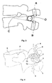
- an interspinous prosthesis according to the invention provided with staples is observed and mounted on the spinous process 1 of a lumbar vertebra 2.
- the interspinous prosthesis shown comprises a torsion spring having two branches 3 and 4.
- the spring used has contiguous turns.
- Each of the ends of the two branches 3 and 4 comprises a fixation system to an apophysis of a vertebra which is a staple 5.
- the staple 5 comprises a generally flat elongated blade whose ends are curved on the same side to form a hook 6 , 7 to hang on the apophysis 1.
- the spacing between the curved parts 6,7 is adapted to the size of the process.
- the elongate blade is Y-shaped to form two hooks 7 on one side and a single hook 6 on the other.
- the upper branch 4 of the spring is folded a first time parallel to the axis of the spring, to the left, at the exit of the turns, and a second time at the other end of the turns, on the right side and at right angles, so that the two branches 3,4 are essentially located in the same plane and that the axis of the spring is perpendicular to this plane.
- the face of the elongate blade opposite that forming a hook comprises a pin 8 for fixing the end of a branch 3.4 of the spring, through a loop provided at this level. This leaves free the relative rotation between the two parts.
- the axis of the spring is spaced from the line joining the center of the hooks 6 (offset relative thereto).
- the two branches 3,4 are curved in an arc, almost from the turns of the spring, over more than 50% of their length.
- the interspinous prosthesis of the invention has a center of rotation located a little below the vertebral plate 9 of the vertebra lower 2 of the instrumented segment, and at its rear part (the upper vertebra on which attaches the second clip is not shown).
- the nipples 8 are provided with a shoulder towards the front of the figure to sandwich the branches 3,4 of the spring between said shoulder and the elongate blade of the clip 5.
- the elongate blade, on the side opposite to that comprising the nipple 8 is folded to the right to form hooks 6,7, a hook 6 located upwards and two hooks 7 located downwards for the upper staple and the reverse for the lower staple.
- the figure 2 represents a variant of the invention.
- the clip 5 also comprises a generally flat elongate blade whose ends are curved on the same side to form a hook 6,7 to hang on the apophysis 1, but the blade consists of several pieces.
- the outer sliding portion 12 comprises an elongated longitudinal lumen 13 while the inner portion 11 comprises a threaded bolt for guiding and locking the clamp on the apophysis 1 by cooperation with a thread provided in the inner portion 11 of the blade.
- the screwing of the threaded bolt in the inner part 11 of the blade blocks the sliding and makes the clip 5 integral with the process 1.
- the two branches 3 and 4 of the spring are welded to the inner part 11 of the clip 5.
- the spring has an instantaneous center of rotation C close to that of a healthy person (under the lower vertebrae plate, in the posterior third).
- the axis O of the spring is shifted relative to the line AB joining the centers of the external fixation hooks of the prosthesis on the apophyses.
- the branches 3 and 4 are folded in hairpin and have an elongated bowl-shaped piece serving as the first hook 7, internal.
- this piece has been welded to the branches at the pin.
- the branches continue outwardly forming a first V (thus forming 2 open triangles T1 and T2) whose outer end of the branch is folded in a loop, parallel to the axis of the spring, to form the second hook 6, external.
- the V-shaped portions of the branches are substantially in the same plane, said plane being perpendicular to the axis of the spring.
- the branches 3 and 4 because they are folded in V, have a length which gives them sufficient elasticity to allow to separate from each other the hooks 6 and 7 (as represented by the two vertical arrows).
- a clamp can be used for this purpose. The release of the clamp allows the secure fixation of the prosthesis on the apophyses 1. It goes without saying that a curved shape of the branches 3 and 4, as shown in FIG. figure 1 also suitable.
Landscapes
- Health & Medical Sciences (AREA)
- Orthopedic Medicine & Surgery (AREA)
- Neurology (AREA)
- Life Sciences & Earth Sciences (AREA)
- Surgery (AREA)
- Engineering & Computer Science (AREA)
- Biomedical Technology (AREA)
- General Health & Medical Sciences (AREA)
- Veterinary Medicine (AREA)
- Heart & Thoracic Surgery (AREA)
- Public Health (AREA)
- Animal Behavior & Ethology (AREA)
- Molecular Biology (AREA)
- Nuclear Medicine, Radiotherapy & Molecular Imaging (AREA)
- Medical Informatics (AREA)
- Vascular Medicine (AREA)
- Transplantation (AREA)
- Oral & Maxillofacial Surgery (AREA)
- Cardiology (AREA)
- Prostheses (AREA)
- Surgical Instruments (AREA)
- Diaphragms For Electromechanical Transducers (AREA)
- Curing Cements, Concrete, And Artificial Stone (AREA)
- Devices Affording Protection Of Roads Or Walls For Sound Insulation (AREA)
Claims (11)
- Lumbarzwischenwlrbelprothese dadurch gekennzeichnet, dass sie eine Torsionsfeder umfasst, die zwei Zweige (3,4) beinhaltet, deren Jeweiliges Ende ein Befestigungssystem (5) an einer Apophyse (1) eines Wirbels (2) beinhaltet.
- Lumbarzwischenwirbeiprothese nach Anspruch 1, dadurch gekennzeichnet, dass die Achse (O) der Feder versetzt Ist hinsichtlich der Geraden, die die Mitten der Befestigungssysteme auf den Apophysen verbindet.
- Lumbarzwischenwirbelprothese nach Anspruch 1 oder 2, dadurch gekennzeichnet, dass die Enden der Zweige (3,4) der Feder indirekt an den Apophysen (1) befestigt sind mittels eines Befestigungsstückes (5), das sich selbst an den Apophysen (1) fixiert.
- Lumbarzwischenwirbelprothese nach Anspruch 3, dadurch gekennzeichnet, dass das Befestigungsstück (5) eine Klammer ist, die eine im Allgemeinen flache langgestreckte Platte umfasst, deren Enden von derselben Seite aus umgebogen werden, um einen Haken (6,7) zu bilden, um sich auf der Apophyse (1) zu befestigen, für die sie bestimmt Ist.
- Lumbarzwischenwirbelprothese nach Anspruch 4, dadurch gekennzeichnet, dass die langgestreckte Platte eine Y-Form hat, um zwei Haken (7) auf einer Seite und einen einzigen Haken (6) auf der anderen zu bilden.
- Lumbarzwischenwlrbelprothese nach einem der Ansprüche 4 und 5, dadurch gekennzeichnet, dass die Platte zwei Schiebetelle umfasst.
- Lumbarzwischenwirbeiprothese nach einem der Ansprüche 1 oder 2, dadurch gekennzeichnet, dass die Enden der Zweige (3,4) der Feder direkt an den Apophysen (1) befestigt werden.
- Lumbarzwischenwirbeiprothese nach einem der Ansprüche 1 oder 2, dadurch gekennzeichnet, dass die Enden der Zweige (3,4) der Feder direkt an den Apophysen (1) befestigt werden und dadurch dass das Ende jedes Zweiges (3,4) sich zu einer Schleife biegt, um einen Haken (6) zu bilden.
- Lumbarzwischenwirbeiprothese nach einem der Ansprüche 1 bis 8, dadurch gekennzeichnet, dass der Außendurchmesser der Feder von 3 bis 13 mm beiträgt.
- Lumbarzwischenwirbeiprothese nach einem der Ansprüche 1 bis 9, dadurch gekennzeichnet, dass der Durchmesser des konstitutiven Drahtes der Feder von 1 bis 4 mm beträgt.
- Lumbarzwischenwirbeiprothese nach einem der Ansprüche 1 bis 10, dadurch gekennzeichnet, dass die Achse (0) der Feder von 4 bis 18 mm Im Ruhezustand versetzt Ist hinsichtlich der Geraden, die die Mitten der Befestigungssysteme auf den Apophysen (1) verbindet.
Applications Claiming Priority (2)
| Application Number | Priority Date | Filing Date | Title |
|---|---|---|---|
| FR0608155A FR2905848B1 (fr) | 2006-09-18 | 2006-09-18 | Prothese inter-epineuse lombaire et ses applications. |
| PCT/FR2007/051938 WO2008034996A1 (fr) | 2006-09-18 | 2007-09-14 | Prothese inter-epineuse lombaire et ses applications |
Publications (2)
| Publication Number | Publication Date |
|---|---|
| EP2063796A1 EP2063796A1 (de) | 2009-06-03 |
| EP2063796B1 true EP2063796B1 (de) | 2009-12-23 |
Family
ID=37891878
Family Applications (1)
| Application Number | Title | Priority Date | Filing Date |
|---|---|---|---|
| EP07823833A Not-in-force EP2063796B1 (de) | 2006-09-18 | 2007-09-14 | Lumbarzwischenwirbelprothese und ihre anwendungen |
Country Status (13)
| Country | Link |
|---|---|
| US (1) | US20090292314A1 (de) |
| EP (1) | EP2063796B1 (de) |
| JP (1) | JP5000719B2 (de) |
| KR (1) | KR101218809B1 (de) |
| CN (1) | CN101626732B (de) |
| AT (1) | ATE452589T1 (de) |
| BR (1) | BRPI0718489A2 (de) |
| CA (1) | CA2663510A1 (de) |
| DE (1) | DE602007004000D1 (de) |
| ES (1) | ES2338719T3 (de) |
| FR (1) | FR2905848B1 (de) |
| MX (1) | MX2009002938A (de) |
| WO (1) | WO2008034996A1 (de) |
Families Citing this family (30)
| Publication number | Priority date | Publication date | Assignee | Title |
|---|---|---|---|---|
| US8523904B2 (en) | 2004-03-09 | 2013-09-03 | The Board Of Trustees Of The Leland Stanford Junior University | Methods and systems for constraint of spinous processes with attachment |
| US8241330B2 (en) | 2007-01-11 | 2012-08-14 | Lanx, Inc. | Spinous process implants and associated methods |
| US9055981B2 (en) | 2004-10-25 | 2015-06-16 | Lanx, Inc. | Spinal implants and methods |
| KR100817788B1 (ko) * | 2006-09-07 | 2008-03-31 | 박경우 | 척추경 고정용 로드의 제조장치 및 방법과 상기 장치를통해 제조된 로드 |
| US8029541B2 (en) * | 2006-10-19 | 2011-10-04 | Simpirica Spine, Inc. | Methods and systems for laterally stabilized constraint of spinous processes |
| US9265532B2 (en) | 2007-01-11 | 2016-02-23 | Lanx, Inc. | Interspinous implants and methods |
| US20110172708A1 (en) * | 2007-06-22 | 2011-07-14 | Simpirica Spine, Inc. | Methods and systems for increasing the bending stiffness of a spinal segment with elongation limit |
| US20090248078A1 (en) * | 2008-04-01 | 2009-10-01 | Zimmer Spine, Inc. | Spinal stabilization device |
| US9301788B2 (en) * | 2008-04-10 | 2016-04-05 | Life Spine, Inc. | Adjustable spine distraction implant |
| EP2413825A4 (de) | 2009-03-31 | 2013-12-11 | Lanx Inc | Dornfortsatzimplantate und zugehörige verfahren |
| AR073636A1 (es) * | 2009-05-04 | 2010-11-24 | Pixis S A | Implante distractor interespinoso |
| US8114132B2 (en) | 2010-01-13 | 2012-02-14 | Kyphon Sarl | Dynamic interspinous process device |
| US20110257748A1 (en) * | 2010-04-15 | 2011-10-20 | Jung-Tung Liu | Artificial spinal implant |
| EP2722013B1 (de) * | 2011-06-20 | 2016-10-26 | Akita University | Instrument zur immobilisierung der wirbelsäule |
| FR2977139B1 (fr) | 2011-06-30 | 2014-08-22 | Ldr Medical | Implant inter-epineux et instrument d’implantation |
| US11812923B2 (en) | 2011-10-07 | 2023-11-14 | Alan Villavicencio | Spinal fixation device |
| US20140316467A1 (en) * | 2011-10-31 | 2014-10-23 | Nlt Spine Ltd. | Bony structure fixation clamp |
| KR101121667B1 (ko) * | 2012-01-17 | 2012-03-09 | 김창국 | 척추 극돌기 고정장치 |
| US20150305779A1 (en) * | 2012-08-21 | 2015-10-29 | Pierre M. Montavon | Spring and device for stabilizing human or animal bone |
| AU2013308332B2 (en) | 2012-08-31 | 2017-01-19 | Newsouth Innovations Pty Limited | Bone stabilization device and methods of use |
| US9510872B2 (en) * | 2013-03-15 | 2016-12-06 | Jcbd, Llc | Spinal stabilization system |
| ES2526101B1 (es) * | 2013-05-28 | 2015-11-30 | Technology Of Prosthesis S.L | Prótesis interespinosa flexible |
| US9592083B2 (en) * | 2013-08-30 | 2017-03-14 | New South Innovations Pty Limited | Spine stabilization device |
| CN104644253A (zh) * | 2013-11-20 | 2015-05-27 | 杨春 | 拉伸式腰椎后路非融合固定系统 |
| CN105476671B (zh) * | 2014-09-19 | 2018-04-03 | 北京纳通科技集团有限公司 | 撑开器和用于持送撑开器的器械 |
| DE102015104784B4 (de) * | 2015-03-27 | 2018-09-13 | Gert Stephanus Becker | Vorrichtung zur Abstützung einer Wirbelsäule beziehungsweise zur Spreizung zweier benachbarter Rippen |
| KR101686641B1 (ko) * | 2015-05-11 | 2016-12-14 | 부산대학교 산학협력단 | 척추 요추부 극돌기 고정장치 |
| JP6771554B2 (ja) * | 2015-10-21 | 2020-10-21 | 佰奥達生物科技(武漢)股▲ふん▼有限公司 | 棘間ユニバーサル動的ホルダー |
| CN108451618B (zh) * | 2017-02-22 | 2020-10-16 | 医晟有限公司 | 脊椎椎板稳定器 |
| TWI616182B (zh) * | 2016-10-21 | 2018-03-01 | Wang hong zhen | 可伸縮脊椎椎板穩定器 |
Family Cites Families (20)
| Publication number | Priority date | Publication date | Assignee | Title |
|---|---|---|---|---|
| US1920821A (en) * | 1931-09-22 | 1933-08-01 | Wassenaar Jan Jacob Stephanus | Distraction bone forceps |
| US4961743A (en) * | 1989-01-03 | 1990-10-09 | Codman & Shurtleff, Inc. | Torsion spring |
| US5209751A (en) * | 1992-02-19 | 1993-05-11 | Danek Medical, Inc. | Spinal fixation system |
| US5496318A (en) * | 1993-01-08 | 1996-03-05 | Advanced Spine Fixation Systems, Inc. | Interspinous segmental spine fixation device |
| FR2722980B1 (fr) * | 1994-07-26 | 1996-09-27 | Samani Jacques | Implant vertebral inter-epineux |
| EP0743045A2 (de) * | 1995-04-28 | 1996-11-20 | Gazzani, Romolo Igino | Vorrichtungen zur Osteosynthese |
| US5752955A (en) * | 1995-10-30 | 1998-05-19 | Fastenetix, L.L.C. | Sliding shaft variable length cross-link device for use with dual rod apparatus |
| FR2743712B1 (fr) * | 1996-01-19 | 1998-04-30 | Louis Rene | Dispositif d'ancrage d'osteosynthese vertebrale posterieure |
| FR2763236B1 (fr) * | 1997-05-16 | 1999-10-15 | Scient X | Implant pour dispositif d'osteosynthese vertebral du type a crochet |
| FR2774581B1 (fr) * | 1998-02-10 | 2000-08-11 | Dimso Sa | Stabilisateur interepineux a fixer a des apophyses epineuses de deux vertebres |
| US6652527B2 (en) * | 1998-10-20 | 2003-11-25 | St. Francis Medical Technologies, Inc. | Supplemental spine fixation device and method |
| US7674293B2 (en) * | 2004-04-22 | 2010-03-09 | Facet Solutions, Inc. | Crossbar spinal prosthesis having a modular design and related implantation methods |
| TW411838U (en) * | 1999-12-10 | 2000-11-11 | Ye Jung Chiuan | Fastening hook for spine and reposition device for fastening spine |
| US6503281B1 (en) * | 2000-08-25 | 2003-01-07 | Thomas H. Mallory | Total hip replacement |
| DE10236691B4 (de) * | 2002-08-09 | 2005-12-01 | Biedermann Motech Gmbh | Dynamische Stabilisierungseinrichtung für Knochen, insbesondere für Wirbel |
| US20060064165A1 (en) * | 2004-09-23 | 2006-03-23 | St. Francis Medical Technologies, Inc. | Interspinous process implant including a binder and method of implantation |
| DE50311984D1 (de) * | 2003-03-24 | 2009-11-12 | Synthes Gmbh | Bandscheiben- oder zwischenwirbelprothese |
| CN101217917B (zh) * | 2005-04-08 | 2013-07-17 | 帕拉迪格脊骨有限责任公司 | 棘突间脊椎和腰骶稳定装置及使用方法 |
| US7883532B2 (en) * | 2005-04-25 | 2011-02-08 | Spineco, Inc. | Vertebral pars interarticularis clamp a new spine fixation device, instrumentation, and methodology |
| US7922745B2 (en) * | 2006-01-09 | 2011-04-12 | Zimmer Spine, Inc. | Posterior dynamic stabilization of the spine |
-
2006
- 2006-09-18 FR FR0608155A patent/FR2905848B1/fr not_active Expired - Fee Related
-
2007
- 2007-09-14 US US12/441,623 patent/US20090292314A1/en not_active Abandoned
- 2007-09-14 AT AT07823833T patent/ATE452589T1/de not_active IP Right Cessation
- 2007-09-14 JP JP2009527872A patent/JP5000719B2/ja not_active Expired - Fee Related
- 2007-09-14 CA CA002663510A patent/CA2663510A1/fr not_active Abandoned
- 2007-09-14 CN CN2007800344002A patent/CN101626732B/zh not_active Expired - Fee Related
- 2007-09-14 EP EP07823833A patent/EP2063796B1/de not_active Not-in-force
- 2007-09-14 MX MX2009002938A patent/MX2009002938A/es active IP Right Grant
- 2007-09-14 WO PCT/FR2007/051938 patent/WO2008034996A1/fr not_active Ceased
- 2007-09-14 DE DE602007004000T patent/DE602007004000D1/de active Active
- 2007-09-14 BR BRPI0718489-1A patent/BRPI0718489A2/pt not_active Application Discontinuation
- 2007-09-14 ES ES07823833T patent/ES2338719T3/es active Active
- 2007-09-14 KR KR1020097007488A patent/KR101218809B1/ko not_active Expired - Fee Related
Also Published As
| Publication number | Publication date |
|---|---|
| FR2905848B1 (fr) | 2008-12-05 |
| JP5000719B2 (ja) | 2012-08-15 |
| DE602007004000D1 (de) | 2010-02-04 |
| CN101626732B (zh) | 2011-04-06 |
| US20090292314A1 (en) | 2009-11-26 |
| EP2063796A1 (de) | 2009-06-03 |
| WO2008034996A1 (fr) | 2008-03-27 |
| CN101626732A (zh) | 2010-01-13 |
| MX2009002938A (es) | 2009-05-11 |
| BRPI0718489A2 (pt) | 2013-12-03 |
| ES2338719T3 (es) | 2010-05-11 |
| CA2663510A1 (fr) | 2008-03-27 |
| KR20090069292A (ko) | 2009-06-30 |
| FR2905848A1 (fr) | 2008-03-21 |
| ATE452589T1 (de) | 2010-01-15 |
| KR101218809B1 (ko) | 2013-01-18 |
| JP2010503445A (ja) | 2010-02-04 |
Similar Documents
| Publication | Publication Date | Title |
|---|---|---|
| WO2008034996A1 (fr) | Prothese inter-epineuse lombaire et ses applications | |
| EP2521500B1 (de) | Vertebrale befestigungsvorrichtung | |
| EP1113758B1 (de) | Vorrichtung zur posterioren wirbelsäulenosteosynthese | |
| EP1439790B9 (de) | Wirbelsäulenstützvorrichtung, die mit klemmen zusammengesetzt ist | |
| EP2725993B1 (de) | Vorrichtung für wirbelfixierung | |
| EP1865863B1 (de) | Intervertebrales implantat für das lumbrosakralgelenk | |
| EP0596788B1 (de) | Osteosynthesevorrichtung zur Wirbelsäulenverfestigung | |
| EP2392277B1 (de) | Wirbelsäulen-Fixierungsvorrichtung | |
| EP1924210B1 (de) | Zwischenwirbelimplantat für das lumbosakralgelenk | |
| EP2858580B1 (de) | Befestigungssystem für gelenkige facetten und anwendungen davon | |
| EP2833810B1 (de) | Chirurgisches instrument und system zur wirbelfixation | |
| EP2555697B1 (de) | Querlaufendes verbindungssystem und vorrichtung für die wirbelsäule | |
| FR2545350A1 (fr) | Dispositif pour l'etaiement du rachis | |
| FR2918555A1 (fr) | Dispositif et systeme de liaison rachidienne transverse | |
| FR2788958A1 (fr) | Retracteur de tissus pour la chirurgie rachidienne par voie posterieure | |
| WO2013083811A1 (fr) | Systeme de pincement osseux | |
| EP2609882B1 (de) | Wirbelbefestigungsvorrichtung | |
| EP3082630B1 (de) | Wirbelfixiervorrichtung mit doppelter befestigung, system zur blockierung einer schleife mit solch einer vorrichtung | |
| EP4149376B1 (de) | Implantierbare vorrichtung, insbesondere vom typ eines zwischenwirbel-spacers | |
| FR2831419A1 (fr) | Appareil de maintien du rachis a assemblage a rotule | |
| WO2010136665A1 (fr) | Système pour relier deux processus épineux | |
| FR2835733A1 (fr) | Patte pour fixer au moins deux portions d'os l'une par rapport a l'autre | |
| FR2779936A1 (fr) | Element stabilisateur pour dispositif chirurgical, notamment d'osteosynthese rachidienne |
Legal Events
| Date | Code | Title | Description |
|---|---|---|---|
| PUAI | Public reference made under article 153(3) epc to a published international application that has entered the european phase |
Free format text: ORIGINAL CODE: 0009012 |
|
| 17P | Request for examination filed |
Effective date: 20090310 |
|
| AK | Designated contracting states |
Kind code of ref document: A1 Designated state(s): AT BE BG CH CY CZ DE DK EE ES FI FR GB GR HU IE IS IT LI LT LU LV MC MT NL PL PT RO SE SI SK TR |
|
| AX | Request for extension of the european patent |
Extension state: AL BA HR MK RS |
|
| GRAP | Despatch of communication of intention to grant a patent |
Free format text: ORIGINAL CODE: EPIDOSNIGR1 |
|
| GRAS | Grant fee paid |
Free format text: ORIGINAL CODE: EPIDOSNIGR3 |
|
| GRAA | (expected) grant |
Free format text: ORIGINAL CODE: 0009210 |
|
| AK | Designated contracting states |
Kind code of ref document: B1 Designated state(s): AT BE BG CH CY CZ DE DK EE ES FI FR GB GR HU IE IS IT LI LT LU LV MC MT NL PL PT RO SE SI SK TR |
|
| REG | Reference to a national code |
Ref country code: GB Ref legal event code: FG4D Free format text: NOT ENGLISH |
|
| REG | Reference to a national code |
Ref country code: CH Ref legal event code: EP |
|
| REG | Reference to a national code |
Ref country code: IE Ref legal event code: FG4D |
|
| REF | Corresponds to: |
Ref document number: 602007004000 Country of ref document: DE Date of ref document: 20100204 Kind code of ref document: P |
|
| REG | Reference to a national code |
Ref country code: CH Ref legal event code: NV Representative=s name: ISLER & PEDRAZZINI AG |
|
| REG | Reference to a national code |
Ref country code: NL Ref legal event code: VDEP Effective date: 20091223 |
|
| PG25 | Lapsed in a contracting state [announced via postgrant information from national office to epo] |
Ref country code: FI Free format text: LAPSE BECAUSE OF FAILURE TO SUBMIT A TRANSLATION OF THE DESCRIPTION OR TO PAY THE FEE WITHIN THE PRESCRIBED TIME-LIMIT Effective date: 20091223 Ref country code: LT Free format text: LAPSE BECAUSE OF FAILURE TO SUBMIT A TRANSLATION OF THE DESCRIPTION OR TO PAY THE FEE WITHIN THE PRESCRIBED TIME-LIMIT Effective date: 20091223 Ref country code: SE Free format text: LAPSE BECAUSE OF FAILURE TO SUBMIT A TRANSLATION OF THE DESCRIPTION OR TO PAY THE FEE WITHIN THE PRESCRIBED TIME-LIMIT Effective date: 20091223 |
|
| REG | Reference to a national code |
Ref country code: ES Ref legal event code: FG2A Ref document number: 2338719 Country of ref document: ES Kind code of ref document: T3 |
|
| LTIE | Lt: invalidation of european patent or patent extension |
Effective date: 20091223 |
|
| PG25 | Lapsed in a contracting state [announced via postgrant information from national office to epo] |
Ref country code: PL Free format text: LAPSE BECAUSE OF FAILURE TO SUBMIT A TRANSLATION OF THE DESCRIPTION OR TO PAY THE FEE WITHIN THE PRESCRIBED TIME-LIMIT Effective date: 20091223 Ref country code: SI Free format text: LAPSE BECAUSE OF FAILURE TO SUBMIT A TRANSLATION OF THE DESCRIPTION OR TO PAY THE FEE WITHIN THE PRESCRIBED TIME-LIMIT Effective date: 20091223 Ref country code: LV Free format text: LAPSE BECAUSE OF FAILURE TO SUBMIT A TRANSLATION OF THE DESCRIPTION OR TO PAY THE FEE WITHIN THE PRESCRIBED TIME-LIMIT Effective date: 20091223 |
|
| PG25 | Lapsed in a contracting state [announced via postgrant information from national office to epo] |
Ref country code: AT Free format text: LAPSE BECAUSE OF FAILURE TO SUBMIT A TRANSLATION OF THE DESCRIPTION OR TO PAY THE FEE WITHIN THE PRESCRIBED TIME-LIMIT Effective date: 20091223 |
|
| REG | Reference to a national code |
Ref country code: IE Ref legal event code: FD4D |
|
| PG25 | Lapsed in a contracting state [announced via postgrant information from national office to epo] |
Ref country code: IS Free format text: LAPSE BECAUSE OF FAILURE TO SUBMIT A TRANSLATION OF THE DESCRIPTION OR TO PAY THE FEE WITHIN THE PRESCRIBED TIME-LIMIT Effective date: 20100423 Ref country code: EE Free format text: LAPSE BECAUSE OF FAILURE TO SUBMIT A TRANSLATION OF THE DESCRIPTION OR TO PAY THE FEE WITHIN THE PRESCRIBED TIME-LIMIT Effective date: 20091223 Ref country code: RO Free format text: LAPSE BECAUSE OF FAILURE TO SUBMIT A TRANSLATION OF THE DESCRIPTION OR TO PAY THE FEE WITHIN THE PRESCRIBED TIME-LIMIT Effective date: 20091223 Ref country code: NL Free format text: LAPSE BECAUSE OF FAILURE TO SUBMIT A TRANSLATION OF THE DESCRIPTION OR TO PAY THE FEE WITHIN THE PRESCRIBED TIME-LIMIT Effective date: 20091223 Ref country code: PT Free format text: LAPSE BECAUSE OF FAILURE TO SUBMIT A TRANSLATION OF THE DESCRIPTION OR TO PAY THE FEE WITHIN THE PRESCRIBED TIME-LIMIT Effective date: 20100423 Ref country code: BG Free format text: LAPSE BECAUSE OF FAILURE TO SUBMIT A TRANSLATION OF THE DESCRIPTION OR TO PAY THE FEE WITHIN THE PRESCRIBED TIME-LIMIT Effective date: 20100323 |
|
| PG25 | Lapsed in a contracting state [announced via postgrant information from national office to epo] |
Ref country code: SK Free format text: LAPSE BECAUSE OF FAILURE TO SUBMIT A TRANSLATION OF THE DESCRIPTION OR TO PAY THE FEE WITHIN THE PRESCRIBED TIME-LIMIT Effective date: 20091223 Ref country code: CZ Free format text: LAPSE BECAUSE OF FAILURE TO SUBMIT A TRANSLATION OF THE DESCRIPTION OR TO PAY THE FEE WITHIN THE PRESCRIBED TIME-LIMIT Effective date: 20091223 |
|
| PG25 | Lapsed in a contracting state [announced via postgrant information from national office to epo] |
Ref country code: IE Free format text: LAPSE BECAUSE OF FAILURE TO SUBMIT A TRANSLATION OF THE DESCRIPTION OR TO PAY THE FEE WITHIN THE PRESCRIBED TIME-LIMIT Effective date: 20091223 Ref country code: GR Free format text: LAPSE BECAUSE OF FAILURE TO SUBMIT A TRANSLATION OF THE DESCRIPTION OR TO PAY THE FEE WITHIN THE PRESCRIBED TIME-LIMIT Effective date: 20100324 Ref country code: CY Free format text: LAPSE BECAUSE OF FAILURE TO SUBMIT A TRANSLATION OF THE DESCRIPTION OR TO PAY THE FEE WITHIN THE PRESCRIBED TIME-LIMIT Effective date: 20091223 |
|
| PLBE | No opposition filed within time limit |
Free format text: ORIGINAL CODE: 0009261 |
|
| STAA | Information on the status of an ep patent application or granted ep patent |
Free format text: STATUS: NO OPPOSITION FILED WITHIN TIME LIMIT |
|
| 26N | No opposition filed |
Effective date: 20100924 |
|
| PG25 | Lapsed in a contracting state [announced via postgrant information from national office to epo] |
Ref country code: DK Free format text: LAPSE BECAUSE OF FAILURE TO SUBMIT A TRANSLATION OF THE DESCRIPTION OR TO PAY THE FEE WITHIN THE PRESCRIBED TIME-LIMIT Effective date: 20091223 |
|
| PG25 | Lapsed in a contracting state [announced via postgrant information from national office to epo] |
Ref country code: MC Free format text: LAPSE BECAUSE OF NON-PAYMENT OF DUE FEES Effective date: 20100930 |
|
| PG25 | Lapsed in a contracting state [announced via postgrant information from national office to epo] |
Ref country code: MT Free format text: LAPSE BECAUSE OF FAILURE TO SUBMIT A TRANSLATION OF THE DESCRIPTION OR TO PAY THE FEE WITHIN THE PRESCRIBED TIME-LIMIT Effective date: 20091223 |
|
| PG25 | Lapsed in a contracting state [announced via postgrant information from national office to epo] |
Ref country code: HU Free format text: LAPSE BECAUSE OF FAILURE TO SUBMIT A TRANSLATION OF THE DESCRIPTION OR TO PAY THE FEE WITHIN THE PRESCRIBED TIME-LIMIT Effective date: 20100624 Ref country code: LU Free format text: LAPSE BECAUSE OF NON-PAYMENT OF DUE FEES Effective date: 20100914 |
|
| PG25 | Lapsed in a contracting state [announced via postgrant information from national office to epo] |
Ref country code: TR Free format text: LAPSE BECAUSE OF FAILURE TO SUBMIT A TRANSLATION OF THE DESCRIPTION OR TO PAY THE FEE WITHIN THE PRESCRIBED TIME-LIMIT Effective date: 20091223 |
|
| REG | Reference to a national code |
Ref country code: FR Ref legal event code: PLFP Year of fee payment: 9 |
|
| REG | Reference to a national code |
Ref country code: FR Ref legal event code: PLFP Year of fee payment: 10 |
|
| REG | Reference to a national code |
Ref country code: FR Ref legal event code: PLFP Year of fee payment: 11 |
|
| REG | Reference to a national code |
Ref country code: FR Ref legal event code: PLFP Year of fee payment: 12 |
|
| PGFP | Annual fee paid to national office [announced via postgrant information from national office to epo] |
Ref country code: IT Payment date: 20210910 Year of fee payment: 15 Ref country code: FR Payment date: 20210824 Year of fee payment: 15 Ref country code: CH Payment date: 20210920 Year of fee payment: 15 |
|
| PGFP | Annual fee paid to national office [announced via postgrant information from national office to epo] |
Ref country code: GB Payment date: 20210928 Year of fee payment: 15 Ref country code: DE Payment date: 20210908 Year of fee payment: 15 Ref country code: BE Payment date: 20210927 Year of fee payment: 15 |
|
| PGFP | Annual fee paid to national office [announced via postgrant information from national office to epo] |
Ref country code: ES Payment date: 20211005 Year of fee payment: 15 |
|
| REG | Reference to a national code |
Ref country code: DE Ref legal event code: R119 Ref document number: 602007004000 Country of ref document: DE |
|
| REG | Reference to a national code |
Ref country code: CH Ref legal event code: PL |
|
| GBPC | Gb: european patent ceased through non-payment of renewal fee |
Effective date: 20220914 |
|
| REG | Reference to a national code |
Ref country code: BE Ref legal event code: MM Effective date: 20220930 |
|
| PG25 | Lapsed in a contracting state [announced via postgrant information from national office to epo] |
Ref country code: LI Free format text: LAPSE BECAUSE OF NON-PAYMENT OF DUE FEES Effective date: 20220930 Ref country code: FR Free format text: LAPSE BECAUSE OF NON-PAYMENT OF DUE FEES Effective date: 20220930 Ref country code: DE Free format text: LAPSE BECAUSE OF NON-PAYMENT OF DUE FEES Effective date: 20230401 Ref country code: CH Free format text: LAPSE BECAUSE OF NON-PAYMENT OF DUE FEES Effective date: 20220930 |
|
| PG25 | Lapsed in a contracting state [announced via postgrant information from national office to epo] |
Ref country code: BE Free format text: LAPSE BECAUSE OF NON-PAYMENT OF DUE FEES Effective date: 20220930 |
|
| REG | Reference to a national code |
Ref country code: ES Ref legal event code: FD2A Effective date: 20231027 |
|
| PG25 | Lapsed in a contracting state [announced via postgrant information from national office to epo] |
Ref country code: GB Free format text: LAPSE BECAUSE OF NON-PAYMENT OF DUE FEES Effective date: 20220914 |
|
| PG25 | Lapsed in a contracting state [announced via postgrant information from national office to epo] |
Ref country code: ES Free format text: LAPSE BECAUSE OF NON-PAYMENT OF DUE FEES Effective date: 20220915 |
|
| PG25 | Lapsed in a contracting state [announced via postgrant information from national office to epo] |
Ref country code: ES Free format text: LAPSE BECAUSE OF NON-PAYMENT OF DUE FEES Effective date: 20220915 |
|
| PG25 | Lapsed in a contracting state [announced via postgrant information from national office to epo] |
Ref country code: IT Free format text: LAPSE BECAUSE OF NON-PAYMENT OF DUE FEES Effective date: 20220914 |