EP2064530B1 - Multisensormessanordnung für füllstandsmessgerät an bord eines flugzeuges - Google Patents
Multisensormessanordnung für füllstandsmessgerät an bord eines flugzeuges Download PDFInfo
- Publication number
- EP2064530B1 EP2064530B1 EP07823843.3A EP07823843A EP2064530B1 EP 2064530 B1 EP2064530 B1 EP 2064530B1 EP 07823843 A EP07823843 A EP 07823843A EP 2064530 B1 EP2064530 B1 EP 2064530B1
- Authority
- EP
- European Patent Office
- Prior art keywords
- measuring device
- sensors
- sensor
- holding means
- fuel
- Prior art date
- Legal status (The legal status is an assumption and is not a legal conclusion. Google has not performed a legal analysis and makes no representation as to the accuracy of the status listed.)
- Active
Links
- 239000000523 sample Substances 0.000 title claims description 39
- 239000000446 fuel Substances 0.000 claims description 28
- 238000005259 measurement Methods 0.000 claims description 28
- XLYOFNOQVPJJNP-UHFFFAOYSA-N water Substances O XLYOFNOQVPJJNP-UHFFFAOYSA-N 0.000 claims description 7
- 239000000463 material Substances 0.000 claims description 5
- 238000012545 processing Methods 0.000 claims description 4
- 229920000515 polycarbonate Polymers 0.000 claims description 3
- 239000004417 polycarbonate Substances 0.000 claims description 3
- 239000002828 fuel tank Substances 0.000 claims description 2
- 239000011810 insulating material Substances 0.000 claims description 2
- 239000003990 capacitor Substances 0.000 description 3
- 238000009434 installation Methods 0.000 description 3
- 238000012423 maintenance Methods 0.000 description 3
- 230000007257 malfunction Effects 0.000 description 2
- 238000000034 method Methods 0.000 description 2
- 238000012935 Averaging Methods 0.000 description 1
- 238000009530 blood pressure measurement Methods 0.000 description 1
- 238000004891 communication Methods 0.000 description 1
- 238000011109 contamination Methods 0.000 description 1
- 238000001739 density measurement Methods 0.000 description 1
- 230000006866 deterioration Effects 0.000 description 1
- 239000012530 fluid Substances 0.000 description 1
- 230000004907 flux Effects 0.000 description 1
- 238000007689 inspection Methods 0.000 description 1
- 239000003350 kerosene Substances 0.000 description 1
- 238000004377 microelectronic Methods 0.000 description 1
- 238000005086 pumping Methods 0.000 description 1
- 230000002787 reinforcement Effects 0.000 description 1
- 230000000284 resting effect Effects 0.000 description 1
- 125000006850 spacer group Chemical group 0.000 description 1
- 239000000126 substance Substances 0.000 description 1
- 230000026676 system process Effects 0.000 description 1
- 239000012815 thermoplastic material Substances 0.000 description 1
Images



Classifications
-
- G—PHYSICS
- G01—MEASURING; TESTING
- G01F—MEASURING VOLUME, VOLUME FLOW, MASS FLOW OR LIQUID LEVEL; METERING BY VOLUME
- G01F23/00—Indicating or measuring liquid level or level of fluent solid material, e.g. indicating in terms of volume or indicating by means of an alarm
- G01F23/22—Indicating or measuring liquid level or level of fluent solid material, e.g. indicating in terms of volume or indicating by means of an alarm by measuring physical variables, other than linear dimensions, pressure or weight, dependent on the level to be measured, e.g. by difference of heat transfer of steam or water
- G01F23/26—Indicating or measuring liquid level or level of fluent solid material, e.g. indicating in terms of volume or indicating by means of an alarm by measuring physical variables, other than linear dimensions, pressure or weight, dependent on the level to be measured, e.g. by difference of heat transfer of steam or water by measuring variations of capacity or inductance of capacitors or inductors arising from the presence of liquid or fluent solid material in the electric or electromagnetic fields
- G01F23/263—Indicating or measuring liquid level or level of fluent solid material, e.g. indicating in terms of volume or indicating by means of an alarm by measuring physical variables, other than linear dimensions, pressure or weight, dependent on the level to be measured, e.g. by difference of heat transfer of steam or water by measuring variations of capacity or inductance of capacitors or inductors arising from the presence of liquid or fluent solid material in the electric or electromagnetic fields by measuring variations in capacitance of capacitors
- G01F23/268—Indicating or measuring liquid level or level of fluent solid material, e.g. indicating in terms of volume or indicating by means of an alarm by measuring physical variables, other than linear dimensions, pressure or weight, dependent on the level to be measured, e.g. by difference of heat transfer of steam or water by measuring variations of capacity or inductance of capacitors or inductors arising from the presence of liquid or fluent solid material in the electric or electromagnetic fields by measuring variations in capacitance of capacitors mounting arrangements of probes
Definitions
- the present invention relates to the field of fuel gauging systems, in particular for application in aeronautics.
- a capacitive type gauging probe comprising two electrodes in the form of cylindrical tubes arranged one inside the other in a coaxial manner. The probe is open at both ends so that the fuel freely enters the space between the electrodes. The capacity of the capacitor formed by the two electrodes depends linearly on the height of the fuel column between the two tubes. A description of such a capacitive probe can be found for example in the patent application FR-A-2582396 .
- the capacitive probes are not entirely satisfactory, however. Indeed, the value of the measured capacity is a function of the dielectric coefficient of the fuel. However, the latter varies according to the quality of the fuel and its rate of possible contamination by water, depending on the refueling.
- this system comprises a plurality of capacitive probes, called primary probes, high level detectors, low level detectors, sensors for measuring permittivity, density, temperature, etc.
- secondary a second type of gauging probe, which can be used on the ground in the event of failure of the primary probes.
- Patent documents US 4,434,657 A1 , US 5 187 979 A1 and US 4,420,976 A1 also describe measuring devices for a fuel gauging system.
- the primary purpose of the present invention is to provide a fuel gauging system for easy installation and maintenance which does not require perforation of the tank.
- a second aim of the invention is to propose a measuring device with microelectromechanical sensors (MEMS) which can be easily integrated into existing gauging systems.
- MEMS microelectromechanical sensors
- the present invention is defined by a multisensor measuring device for a fuel gauging system according to claim 1.
- Said plurality of sensors preferably comprises at least one pressure sensor and one density sensor. It can also include at least one permittivity sensor.
- said plurality of sensors comprises sensors of identical nature.
- the insert has an annular shape and has a threaded axial bore.
- the first holding means preferably consist of a first cylindrical part, coaxial with the insert, and ending at its upper part by a threaded tubular head intended to be screwed into said bore, said cylindrical part being pierced by an axial hole , from side to side.
- the second holding means are preferably constituted by a second cylindrical part, coaxial with the first, and pierced by an axial hole, right through.
- connection interface common to the various sensors can be mounted on the exterior surface of the annular film, the connection wires between said sensors and said interface then being embedded in the material of said film.
- the material of said film is advantageously polycarbonate.
- said quick fixing means comprise, on the one hand, pins mounted on one of the first and second cylindrical parts, and, on the other hand, corresponding bores in the other part, said pins being sized to forcefully engage in said corresponding bores.
- said quick fixing means comprise, on the one hand, snap-on fingers forming an integral part of one of the first and second cylindrical parts, and on the other hand, a corresponding groove in the other part , said fingers being adapted to snap into said corresponding groove.
- the gauging system may further comprise a plurality of auxiliary sensors installed in said plurality of tanks, each auxiliary sensor belonging to an assembly consisting of a high level detector, a low level detector, a water presence detector and a temperature sensor, each auxiliary sensor being connected to one of said local processors, the latter being adapted to process the measurement data coming from said auxiliary sensor.
- the auxiliary sensors are MEMS sensors.
- each MEMS sensor is advantageously mounted on the interior surface of a stirrup, the legs of which are bolted to the internal structure of the aircraft.
- the idea underlying the present invention is to use the primary capacitive probes to integrate a multi-sensor measurement device, in particular with MEMS sensors.
- the Fig. 1 shows schematically a capacitive probe 100 of the prior art which has been equipped with the multisensor measuring device 150 according to the invention.
- the capacitive probe comprises two coaxial metallic cylindrical tubes 110, 120, the outer tube 120 being fixed by means of insulating flanges 130, 140 on an internal frame of the tank at a predetermined height.
- the inner tube 110 does not descend to the lower end of the outer tube 120, so that free space is available at the base of the capacitive probe.
- the multisensor measuring device 150 advantageously engages in this available space, as will be seen more clearly below.
- the capacitive probe 100 and the multisensor measuring device 150 each have their own connector, designated by 135 and 145, respectively.
- the connection wires 141 carry low voltage signals and are preferably shielded to provide protection against electromagnetic interference, in particular against that generated by the signals passing through the connection wires 131.
- the signals from the capacitive probe 100 and the sensors of the measurement device 150 are processed by a local processor, advantageously but not necessarily installed in the measurement device itself, before being transmitted via a data bus to the central processor of the gauging system.
- the Fig. 2 represents an exploded view showing the lower part of the capacitive probe as well as the detail of the structure of the measuring device 150.
- the multi-sensor measuring device mainly comprises an insert 160, a first cylindrical part 180 and a second cylindrical part 190.
- the insert 160 is in the form of an annular part with an outside diameter substantially equal to the inside diameter of the cylindrical tube 120, and mounted forcefully inside the latter without however, distort it. Once the insert is in place, its base is flush with the lower end of the tube. The position of the insert along the axis of the capacitive probe is thus perfectly determined.
- the insert is housed under the inner cylindrical tube 110, so that the capacitive measurement is not affected by its presence. It has a threaded axial bore 161 into which a threaded tubular head 181 is screwed, forming an integral part of the first cylindrical part 180.
- the external diameter of the first cylindrical part 180 is substantially equal to the external diameter of the tube 120. It comprises at its upper part the threaded tubular head 181, intended to be screwed into the insert.
- the assembly constituted by the insert and the tube comes to rest on a shoulder 182 when the first cylindrical part is in the screwed position.
- a seal 170 can be placed, as indicated, on the shoulder 182 so as to avoid any deterioration of the tube 120 during tightening.
- the insert may have at its base a shoulder of diameter equal to or greater than the outside diameter of the tube, the base of the tube then resting directly on said shoulder.
- the outer surface of the cylindrical part 180 is preferably knurled over at least part 183 of its height in order to facilitate its tightening. As will be detailed below, this part comprises at its lower part first rapid fixing means 185 (not visible in this figure).
- the second cylindrical part 190 is also of outside diameter substantially equal to that of the tube 120 and is advantageously knurled over at least part 191 of its height.
- Second quick fixing means 195 are an integral part of the part 190 or are fixed to the upper part of the latter. The first and second quick fixing means 185 and 195 cooperate to secure the first and second cylindrical parts 180 and 190.
- the second quick fixing means 195 consist of pins arranged parallel to the axis of revolution of the second cylindrical part 190 and mounted in the upper part of the latter.
- the first quick fixing means are then constituted by bores 185 in the lower part of the first cylindrical part 180.
- the pins are dimensioned so as to be able to engage in force in the corresponding bores.
- the pins can be provided on the first cylindrical part and the bores in the second cylindrical part.
- the corresponding pins and bores are arranged in a uniform angular distribution in order to distribute the mechanical stresses during tightening.
- the second quick fixing means consist of snap-in fingers, elastically deformable, extending in one or more directions substantially parallel to the axis of revolution of the second cylindrical part.
- Each finger ends with an inclined ramp end which can engage in a circular groove arranged in the lower part of the first cylindrical part 180.
- the latching fingers can be provided on the first cylindrical part and the groove in the second cylindrical part.
- the fingers are arranged in a uniform angular distribution.
- the two cylindrical parts and, where appropriate, the rapid fixing means are advantageously made of thermoplastic material.
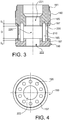
- the Fig. 3 shows an axial section of the two cylindrical parts assembled by the quick fastening means, produced here by pins 195 and corresponding bores 185.
- the first and second quick fixing means also act as spacers between the two cylindrical parts 180 and 190, so that a predetermined distance D is maintained between them.
- Circular grooves 187 and 197 are respectively arranged in the lower surface of the first cylindrical part and the upper surface of the second cylindrical part. These grooves are opposite when the two parts are secured by locking the quick fixing means.
- An annular film 200 carrying MEMS sensors 210, is mounted prisoner between the two cylindrical parts. Its thickness is chosen to be less than the width of the grooves 187 and 197 and its height is chosen to be slightly less than D + g 1 + g 2 where g 1 and g 2 are the respective depths of the two grooves. Thanks to these games, the film retains freedom of rotation inside these grooves even though it is trapped between the two cylindrical parts 180 and 190. In addition, the distance measured on a vertical axis, between the support 200 and the base of the insert 160, is perfectly determined. Thus, once the capacitive probe is installed in a tank at a predetermined height, the height of the sensors is itself perfectly known.
- the first and second cylindrical parts 180, 190 are respectively drilled by axial holes 221, 222 of sufficiently large diameters so that the fuel can freely circulate between the first and the second cylindrical parts, on the one hand, and between the first cylindrical part and the tube 120, on the other hand.
- the number and the angular extension of the rapid fixing means are chosen to be sufficiently small so that the fuel flows freely between the zone 220 and the annular film 200.
- the Fig. 4 shows in top view the second cylindrical part 190.
- the second quick fixing means (constituted here by pins), the circular groove 197 as well as the fuel circulation hole 220.
- the annular film 200 is made of an insulating material, preferably polycarbonate.
- the sensors 210 are mounted on the inner surface of the annular film so that an operator can handle the film without damaging them.
- a connection interface 213, common to the various sensors, is also mounted on the exterior surface of the annular film. It is advantageously connected to the sensors by means of wires embedded in the material of the film.
- a connector 215 can be coupled to the connection interface to connect the sensors to the local processor or to the central processor. The free rotation of the annular film 200 in the grooves 187 and 197 allows an easy connection operation between the interface 213 and the connector 215, regardless of the position of the latter.
- the second cylindrical part can be easily removed and the annular film replaced.
- the sensors 210 advantageously comprise one, and preferably several, MEMS sensor (s). Some of these sensors have the function of measuring the physico-chemical properties of the fuel, in particular its density, its viscosity or its permittivity.
- MEMS sensor a type of MEMS sensor capable of measuring the density and viscosity of a fluid.
- the permittivity measurement can be obtained from the capacitance measurement of a capacitor whose inter-armature distance or the surface is mechanically varied.
- More conventional microelectronic sensors can also be added to the annular film 200, in particular permittivity or pressure sensors.
- permittivity can be carried out from the measurement of the capacity of a standard capacitor and the measurement of pressure can be obtained from the measurement of voltage of a piezoelectric transducer.
- the sensors will be identical in nature, in other words the same sensor may be provided in several copies, for reasons of security or noise reduction by averaging the measurements.
- the primary fuel height measurement will be obtained from the capacity measurements, provided by the capacitive probe, and the permittivity measurements, provided by the multisensor device.
- the secondary measurement of fuel height will, for example, be obtained from pressure and density measurements provided by the multisensor device. This eliminates the installation of secondary MFLI probes and the disadvantages associated with them.
- the measurement data from the various sensors is transmitted over a data bus to a local processor or, failing this, to the central processor of the gauging system.
- the measurements of capacity, permittivity, pressure and density can be processed by a local processor, advantageously installed or embedded in the body of the second cylindrical part 190.
- the local processor can be deported outside this room in order to process measurement data from a plurality of capacitive probes and their associated multisensor devices.
- the local processor can simply filter and multiplex the data it receives. Alternatively, it performs the calculations for obtaining the primary and / or secondary fuel height measurements and transmits them to the central processor. Communication between the local processor and the central processor will be carried out if necessary by means of a wireless link.
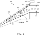
- the Fig. 5 schematically represents a fuel gauging system 300 on board an aircraft. It includes a central processor 310, possibly one or more data concentrator (s) 315, local processors 320, capacitive probes 100 on which multisensor measurement devices 150, denoted P, have been installed, as well as detailed auxiliary sensors 350 further.
- a central processor 310 possibly one or more data concentrator (s) 315, local processors 320, capacitive probes 100 on which multisensor measurement devices 150, denoted P, have been installed, as well as detailed auxiliary sensors 350 further.
- Each local processor 320 is connected to a plurality of capacitive probes (equipped with multisensor devices) as well as to the auxiliary sensors 350 located near it.
- the data processed by the local processors is possibly grouped by a data concentrator before being transmitted to the central processor.
- the central processor calculates in particular the quantity of fuel as a function, on the one hand, of the primary and / or secondary measurements, respectively supplied by the capacitive probes and the multisensor devices, and, on the other hand, of the geometry of the tanks.
- the central processor of the gauging system processes the measurements from the auxiliary sensors and transmits, if necessary, the corresponding alarms to the alarm system in flight.
- auxiliary sensors 350 are temperature sensors 351, low level detectors 352, high level detectors 353 and water presence sensors 354.
- the temperature sensors 351 are notably installed in the external tanks which are more particularly exposed to significant temperature variations. It is indeed important to warn the cockpit when the fuel temperature becomes too low or too high, this situation can affect the proper functioning of the aircraft: a too low temperature increases the viscosity of the fuel and risks leading to pumping difficulties while too high a temperature can cause vapor pockets in the engine supply system.
- low level detectors are placed in the lowest positions of the various tanks and high level detectors are arranged in positions above which an overflow occurs in the balancing tank.
- the water presence detectors are preferably placed in low positions of the tank where the water, because of its higher density than that of kerosene, is likely to accumulate. They can also advantageously be placed near certain capacitive probes, so as to allow identification of a fault in the gauging system.
- the temperature sensors, the high and low level sensors, the water presence detectors are advantageously MEMS sensors.
- the Fig. 6 illustrates one of these sensors 350, mounted on the interior surface of a stirrup 410.
- the legs 411 of the stirrup are bolted, by means of bolts 412 and anchor nuts 413, to the internal structure of the aircraft , for example, as shown on a wing span 420.
- the sensor 350 is placed sheltered from impacts between the structure of the aircraft and the stirrup 410, which considerably reduces the risk of damage during an inspection or maintenance operation.
- the connection of the sensor can be done easily by means of a multi-pin connector 415.
Landscapes
- Physics & Mathematics (AREA)
- Engineering & Computer Science (AREA)
- Power Engineering (AREA)
- Electromagnetism (AREA)
- Thermal Sciences (AREA)
- Fluid Mechanics (AREA)
- General Physics & Mathematics (AREA)
- Measurement Of Levels Of Liquids Or Fluent Solid Materials (AREA)
- Testing Or Calibration Of Command Recording Devices (AREA)
- Investigating Or Analyzing Materials By The Use Of Electric Means (AREA)
- Measurement Of Length, Angles, Or The Like Using Electric Or Magnetic Means (AREA)
Claims (15)
- Multisensor-Messvorrichtung für ein Treibstoffmesssystem, dadurch gekennzeichnet, dass sie enthält:- einen Einsatz (160), der dazu bestimmt ist, gemäß einer Achse an der Basis einer kapazitiven Sonde (100) eingeführt zu werden, die zwei gemäß dieser Achse koaxiale Metallrohre (110, 120) enthält, um eine bezüglich der Sonde vorbestimmte axiale Stellung einzunehmen;- einen ringförmigen Träger (200) aus Isoliermaterial, auf den eine Vielzahl von Sensoren (210) montiert ist, die mindestens einen mikroelektromechanischen Sensor enthält;- Halteeinrichtungen (180, 185, 190, 195), um den ringförmigen Träger gemäß der Achse in einem vorbestimmten Abstand zum Einsatz zu halten, wobei die Halteeinrichtungen erste Halteeinrichtungen (180), die auf den Einsatz montiert sind, und zweite Halteeinrichtungen (190) aufweisen, die mit Hilfe von Schnellbefestigungseinrichtungen (185, 195) auf die ersten montiert sind, wobei der Träger (200) zwischen den ersten und den zweiten Halteeinrichtungen eingeschlossen ist, wenn die Schnellbefestigungseinrichtungen verriegelt sind, wobei die ersten und zweiten Halteeinrichtungen (180) erste bzw. zweite zylindrische Bauteile enthalten,
und dass eine erste und eine zweite Kreisnut (187, 197) in der unteren Fläche des ersten zylindrischen Bauteils bzw. in der oberen Fläche des zweiten zylindrischen Bauteils einander gegenüber angeordnet sind, wobei der Träger (200) aus einer ringförmigen Folie besteht, deren oberer Teil frei in die erste Nut (187) eingesetzt und der untere Teil frei in die zweite Nut (197) eingesetzt ist. - Messvorrichtung nach Anspruch 1, dadurch gekennzeichnet, dass die Vielzahl von Sensoren mindestens einen Drucksensor und einen Dichtesensor enthält.
- Messvorrichtung nach einem der vorhergehenden Ansprüche, dadurch gekennzeichnet, dass sie mindestens einen Permittivitätssensor enthält.
- Messvorrichtung nach einem der vorhergehenden Ansprüche, dadurch gekennzeichnet, dass der Einsatz (160) eine axiale Gewindebohrung (161) aufweist.
- Messvorrichtung nach Anspruch 4, dadurch gekennzeichnet, dass die ersten Halteeinrichtungen (180) aus dem ersten zylindrischen Bauteil bestehen, das mit dem Einsatz koaxial ist und an seinem oberen Teil in einem rohrförmigen Gewindekopf (181) endet, der dazu bestimmt ist, in die Bohrung geschraubt zu werden, wobei das zylindrische Bauteil von einer Seite zur anderen von einem axialen Loch (221) durchbohrt ist.
- Messvorrichtung nach Anspruch 5, dadurch gekennzeichnet, dass die zweiten Halteeinrichtungen (190) aus dem zweiten zylindrischen Bauteil bestehen, das mit dem ersten koaxial ist und das von einer Seite zur anderen von einem axialen Loch (222) durchbohrt ist.
- Messvorrichtung nach Anspruch 6, dadurch gekennzeichnet, dass eine den verschiedenen Sensoren (210) gemeinsame Verbindungsschnittstelle (213) an die Außenfläche der ringförmigen Folie (200) montiert ist, wobei die Verbindungsdrähte zwischen den Sensoren und der Schnittstelle in das Material der Folie eingebettet sind.
- Messvorrichtung nach Anspruch 7, dadurch gekennzeichnet, dass das Material der Folie Polycarbonat ist.
- Messvorrichtung nach einem der Ansprüche 6 bis 8, dadurch gekennzeichnet, dass die Sensoren an die Innenfläche der ringförmigen Folie montiert sind.
- Messvorrichtung nach Anspruch 6, dadurch gekennzeichnet, dass die Befestigungseinrichtungen einerseits Stifte, die auf eines der ersten und zweiten zylindrischen Bauteile montiert sind, und andererseits entsprechende Bohrungen im anderen Bauteil enthalten, wobei die Stifte bemessen sind, um in die entsprechenden Bohrungen presseingepasst zu werden.
- Messvorrichtung nach Anspruch 6, dadurch gekennzeichnet, dass die Schnellbefestigungseinrichtungen einerseits Einrastfinger, die integrierender Bestandteil eines der ersten und zweiten zylindrischen Bauteile sind, und andererseits eine entsprechende Rille im anderen Bauteil enthalten, wobei die Finger geeignet sind, in die entsprechende Rille einzurasten.
- Kapazitive Sonde, die eine Messvorrichtung nach einem der vorhergehenden Ansprüche aufweist.
- Treibstoffmesssystem an Bord eines Luftfahrzeugs, das enthält:- eine Vielzahl kapazitiver Sonden (100), die auf vorbestimmten Höhen in eine Vielzahl von Treibstofftanks eingebaut sind;- eine Vielzahl von Multisensor-Messvorrichtungen (150) nach einem der Ansprüche 1 bis 11, wobei die Vorrichtungen je auf die kapazitiven Sonden montiert sind;- eine Vielzahl lokaler Prozessoren (320), wobei jeder lokale Prozessor geeignet ist, eine Verarbeitung an den von den kapazitiven Sonden der Multisensor-Messvorrichtungen, mit denen er verbunden ist, stammenden Messdaten auszuführen;- einen zentralen Prozessor, der geeignet ist, ausgehend von den so verarbeiteten Daten und den geometrischen Merkmalen der Vielzahl von Tanks die Treibstoffmenge zu berechnen, die diese enthalten.
- Messsystem nach Anspruch 13, dadurch gekennzeichnet, dass es außerdem eine Vielzahl von Hilfssensoren (350) enthält, die in die Vielzahl von Tanks eingebaut sind, wobei jeder Hilfssensor zu einer Einheit gehört, die aus einem Detektor des oberen Pegels, einem Detektor des unteren Pegels, einem Detektor des Vorhandenseins von Wasser und einem Temperaturfühler besteht, wobei jeder Hilfssensor mit einem der lokalen Prozessoren verbunden ist, wobei letzterer geeignet ist, die vom Hilfssensor, mit dem er verbunden ist, stammenden Messdaten zu verarbeiten.
- Messsystem nach Anspruch 14, dadurch gekennzeichnet, dass die Hilfssensoren mikroelektromechanische Sensoren sind.
Applications Claiming Priority (2)
| Application Number | Priority Date | Filing Date | Title |
|---|---|---|---|
| FR0653831A FR2906027B1 (fr) | 2006-09-20 | 2006-09-20 | Dispositif de mesure multicapteur pour sonde de jaugeage embarquee |
| PCT/FR2007/051948 WO2008035002A2 (fr) | 2006-09-20 | 2007-09-17 | Dispositif de mesure multicapteur pour sonde de jaugeage embarquee a bord d ' un avion |
Publications (2)
| Publication Number | Publication Date |
|---|---|
| EP2064530A2 EP2064530A2 (de) | 2009-06-03 |
| EP2064530B1 true EP2064530B1 (de) | 2020-02-26 |
Family
ID=37781777
Family Applications (1)
| Application Number | Title | Priority Date | Filing Date |
|---|---|---|---|
| EP07823843.3A Active EP2064530B1 (de) | 2006-09-20 | 2007-09-17 | Multisensormessanordnung für füllstandsmessgerät an bord eines flugzeuges |
Country Status (9)
| Country | Link |
|---|---|
| US (1) | US8191419B2 (de) |
| EP (1) | EP2064530B1 (de) |
| JP (1) | JP5161224B2 (de) |
| CN (1) | CN101535781B (de) |
| BR (1) | BRPI0716737A2 (de) |
| CA (1) | CA2663702C (de) |
| FR (1) | FR2906027B1 (de) |
| RU (1) | RU2450248C2 (de) |
| WO (1) | WO2008035002A2 (de) |
Families Citing this family (12)
| Publication number | Priority date | Publication date | Assignee | Title |
|---|---|---|---|---|
| DE102005042060A1 (de) * | 2005-05-24 | 2006-11-30 | Continental Teves Ag & Co. Ohg | Rückwirkungsfreie Auskopplung von CAN-Bus-Signalen |
| BR112016001787A2 (pt) * | 2013-08-28 | 2017-08-01 | Sulzer Management Ag | sonda para monitorar o nível de superfície de um fluido em um receptáculo e método para instalar a sonda no receptáculo |
| RU2678760C2 (ru) * | 2014-08-07 | 2019-01-31 | Зе Боинг Компани | Система беспроводных топливных датчиков |
| US9910025B2 (en) | 2015-06-23 | 2018-03-06 | Simmonds Precision Products, Inc. | Integrated active fuel characteristic sensor |
| JP6881705B2 (ja) * | 2016-05-11 | 2021-06-02 | シーメンス・ヘルスケア・ダイアグノスティックス・インコーポレーテッドSiemens Healthcare Diagnostics Inc. | 液面検出機能付き計測プローブのクイック接続構造 |
| US10126158B2 (en) * | 2016-08-22 | 2018-11-13 | The Boeing Company | Systems and methods for determining a fuel level measurement of a fuel tank using optical sensor |
| US10302598B2 (en) | 2016-10-24 | 2019-05-28 | General Electric Company | Corrosion and crack detection for fastener nuts |
| US10627280B2 (en) * | 2017-04-17 | 2020-04-21 | Simmonds Precision Products | Integrated sensor unit for fuel gauging |
| CA3066724C (en) * | 2017-06-07 | 2022-02-22 | Stratosphere, S.A. | Fuel tank with integrated level sensors, in particular for aerial vehicles |
| CN108732223B (zh) * | 2018-05-28 | 2020-05-01 | 山东博远数据服务有限公司 | 一种生物传感装置 |
| CN110307075B (zh) * | 2019-07-19 | 2024-06-04 | 昌谷汽车科技(宁波)有限公司 | 一种汽车水箱温度压强测量系统 |
| FR3164785A1 (fr) * | 2024-07-17 | 2026-01-23 | Safran Aerosystems | Jauge et système de jaugeage de carburant dans un réservoir d’aéronef |
Family Cites Families (8)
| Publication number | Priority date | Publication date | Assignee | Title |
|---|---|---|---|---|
| IT1123980B (it) * | 1979-02-07 | 1986-05-07 | Nira Spa | Dispositivo universale per misure di livello protata e pressione su fluidi pericolosi |
| US4383444A (en) * | 1980-04-21 | 1983-05-17 | Robertshaw Controls Company | Microprocessor based capacitance level detection system |
| US4420976A (en) * | 1981-09-09 | 1983-12-20 | Mcdonnell Douglas Corporation | Multiplexed true mass gaging system |
| JPS5852520A (ja) * | 1981-09-25 | 1983-03-28 | Tatsuno:Kk | 液量測定装置 |
| US5187979A (en) * | 1991-04-26 | 1993-02-23 | Edmark Iii Karl W | Multi-sensor probe assembly and method for fuel storage system including overflow protection means |
| JPH10115536A (ja) * | 1996-10-14 | 1998-05-06 | Denso Corp | 複合センサ |
| NO310322B1 (no) * | 1999-01-11 | 2001-06-18 | Flowsys As | Maling av flerfasestromning i ror |
| JP4188087B2 (ja) * | 2001-03-23 | 2008-11-26 | シュルンベルジェ ホールディングス リミテッド | 流体特性センサー |
-
2006
- 2006-09-20 FR FR0653831A patent/FR2906027B1/fr not_active Expired - Fee Related
-
2007
- 2007-09-17 JP JP2009528766A patent/JP5161224B2/ja not_active Expired - Fee Related
- 2007-09-17 WO PCT/FR2007/051948 patent/WO2008035002A2/fr not_active Ceased
- 2007-09-17 BR BRPI0716737-7A2A patent/BRPI0716737A2/pt not_active IP Right Cessation
- 2007-09-17 US US12/441,486 patent/US8191419B2/en active Active
- 2007-09-17 EP EP07823843.3A patent/EP2064530B1/de active Active
- 2007-09-17 CA CA2663702A patent/CA2663702C/en not_active Expired - Fee Related
- 2007-09-17 RU RU2009114819/28A patent/RU2450248C2/ru not_active IP Right Cessation
- 2007-09-17 CN CN2007800341447A patent/CN101535781B/zh not_active Expired - Fee Related
Non-Patent Citations (1)
| Title |
|---|
| None * |
Also Published As
| Publication number | Publication date |
|---|---|
| US20090234597A1 (en) | 2009-09-17 |
| RU2450248C2 (ru) | 2012-05-10 |
| CN101535781B (zh) | 2012-08-29 |
| CA2663702A1 (en) | 2008-03-27 |
| CA2663702C (en) | 2016-01-19 |
| BRPI0716737A2 (pt) | 2014-11-11 |
| US8191419B2 (en) | 2012-06-05 |
| FR2906027A1 (fr) | 2008-03-21 |
| FR2906027B1 (fr) | 2009-02-20 |
| RU2009114819A (ru) | 2010-10-27 |
| CN101535781A (zh) | 2009-09-16 |
| JP5161224B2 (ja) | 2013-03-13 |
| WO2008035002A2 (fr) | 2008-03-27 |
| EP2064530A2 (de) | 2009-06-03 |
| WO2008035002A3 (fr) | 2008-05-29 |
| JP2010504512A (ja) | 2010-02-12 |
Similar Documents
| Publication | Publication Date | Title |
|---|---|---|
| EP2064530B1 (de) | Multisensormessanordnung für füllstandsmessgerät an bord eines flugzeuges | |
| WO2016193484A1 (fr) | Dispositif de mesure de pression à fiabilité améliorée et procédé de calibrage associé | |
| FR3035209A1 (fr) | Sonde multifonctions de references primaires pour aeronef, systeme de mesure, aeronef et procede d'obtention de grandeurs physiques associes | |
| WO2011134799A1 (fr) | Dispositif de detection de la rupture d'une voie primaire dans un actionneur de commande de vol | |
| FR2896587A1 (fr) | Capteur de detection d'etat d'un liquide. | |
| EP3286529B1 (de) | Ventil mit einem durchflussmesser zur messung eines durchflusses eines fluids im inneren davon | |
| FR3027389A1 (fr) | Systeme de mesure de force tangentielle appliquee par un fluide a sensibilite augmentee | |
| FR2966503A1 (fr) | Montage de capteur pour moteur a turbine | |
| FR2966500A1 (fr) | Systeme de communication pour moteur a turbine | |
| FR3009281A1 (fr) | Aeronef comprenant un systeme de mesure de pression et procede associe | |
| WO2016071635A1 (fr) | Ensemble de mesure capacitive du taux de gaz dans un ecoulement fluide | |
| EP3203198B1 (de) | Tauchdetektor und luftfahrzeug | |
| EP2216633A1 (de) | Anordnung zur Messung eines Füllstandes einer Flüssigkeit in einem Behälter und entsprechendes Fahrzeug | |
| EP3839457B1 (de) | Flugzeugtriebwerk mit einem lufteinlass, an dessen wand ein von einem flexiblen gehäuse umgebenes messgerät mit optischem sensor befestigt ist, und verfahren zur installation des geräts | |
| EP3388808B1 (de) | Druckerfassungsvorrichtung mit mechanischer entkoppelung | |
| EP2939015B1 (de) | Automatisiertes zerstörungsfreies kontrollgerät für versteifer einer flugzeugkompositkomponente | |
| FR2966501A1 (fr) | Capteur a epaulement pour l'absorption de charges gravitationnelles | |
| FR2853069A3 (fr) | Debitmetre selon le principe du vortex | |
| FR3104708A1 (fr) | Capteur de niveau de liquide du type analogique | |
| WO2015091418A1 (fr) | Dispositif de mesure de différences de potentiels électriques pour structure métallique sous-marine équipée d'un système de protection cathodique, et procédé associé | |
| FR3104253A1 (fr) | Capteur, système et procédé de détection d’un niveau de liquide dans un réservoir | |
| EP0605298B1 (de) | Verfahren und Sensor zur Erfassung der Dichte einer Flüssigkeit und Gerät zur Massenbestimmung unter Verwendung eines solchen Sensors | |
| FR3157931A1 (fr) | Dispositif de mesure capacitive d’une quantité de fluide se trouvant dans un réservoir. | |
| EP4632344A1 (de) | Vorrichtung zur steuerung der spannung einer befestigung und steuerungsverfahren dafür | |
| EP3887776A1 (de) | Gedruckte vorrichtung zur erfassung des mindestpegels eines fluids in einem reservoir |
Legal Events
| Date | Code | Title | Description |
|---|---|---|---|
| PUAI | Public reference made under article 153(3) epc to a published international application that has entered the european phase |
Free format text: ORIGINAL CODE: 0009012 |
|
| 17P | Request for examination filed |
Effective date: 20090316 |
|
| AK | Designated contracting states |
Kind code of ref document: A2 Designated state(s): AT BE BG CH CY CZ DE DK EE ES FI FR GB GR HU IE IS IT LI LT LU LV MC MT NL PL PT RO SE SI SK TR |
|
| DAX | Request for extension of the european patent (deleted) | ||
| 17Q | First examination report despatched |
Effective date: 20140409 |
|
| STAA | Information on the status of an ep patent application or granted ep patent |
Free format text: STATUS: EXAMINATION IS IN PROGRESS |
|
| GRAP | Despatch of communication of intention to grant a patent |
Free format text: ORIGINAL CODE: EPIDOSNIGR1 |
|
| STAA | Information on the status of an ep patent application or granted ep patent |
Free format text: STATUS: GRANT OF PATENT IS INTENDED |
|
| INTG | Intention to grant announced |
Effective date: 20190927 |
|
| GRAS | Grant fee paid |
Free format text: ORIGINAL CODE: EPIDOSNIGR3 |
|
| GRAA | (expected) grant |
Free format text: ORIGINAL CODE: 0009210 |
|
| STAA | Information on the status of an ep patent application or granted ep patent |
Free format text: STATUS: THE PATENT HAS BEEN GRANTED |
|
| AK | Designated contracting states |
Kind code of ref document: B1 Designated state(s): AT BE BG CH CY CZ DE DK EE ES FI FR GB GR HU IE IS IT LI LT LU LV MC MT NL PL PT RO SE SI SK TR |
|
| REG | Reference to a national code |
Ref country code: GB Ref legal event code: FG4D Free format text: NOT ENGLISH |
|
| REG | Reference to a national code |
Ref country code: CH Ref legal event code: EP |
|
| REG | Reference to a national code |
Ref country code: DE Ref legal event code: R096 Ref document number: 602007059911 Country of ref document: DE |
|
| REG | Reference to a national code |
Ref country code: AT Ref legal event code: REF Ref document number: 1238206 Country of ref document: AT Kind code of ref document: T Effective date: 20200315 |
|
| REG | Reference to a national code |
Ref country code: IE Ref legal event code: FG4D Free format text: LANGUAGE OF EP DOCUMENT: FRENCH |
|
| PG25 | Lapsed in a contracting state [announced via postgrant information from national office to epo] |
Ref country code: FI Free format text: LAPSE BECAUSE OF FAILURE TO SUBMIT A TRANSLATION OF THE DESCRIPTION OR TO PAY THE FEE WITHIN THE PRESCRIBED TIME-LIMIT Effective date: 20200226 |
|
| REG | Reference to a national code |
Ref country code: NL Ref legal event code: MP Effective date: 20200226 |
|
| REG | Reference to a national code |
Ref country code: LT Ref legal event code: MG4D |
|
| PG25 | Lapsed in a contracting state [announced via postgrant information from national office to epo] |
Ref country code: SE Free format text: LAPSE BECAUSE OF FAILURE TO SUBMIT A TRANSLATION OF THE DESCRIPTION OR TO PAY THE FEE WITHIN THE PRESCRIBED TIME-LIMIT Effective date: 20200226 Ref country code: BG Free format text: LAPSE BECAUSE OF FAILURE TO SUBMIT A TRANSLATION OF THE DESCRIPTION OR TO PAY THE FEE WITHIN THE PRESCRIBED TIME-LIMIT Effective date: 20200526 Ref country code: IS Free format text: LAPSE BECAUSE OF FAILURE TO SUBMIT A TRANSLATION OF THE DESCRIPTION OR TO PAY THE FEE WITHIN THE PRESCRIBED TIME-LIMIT Effective date: 20200626 Ref country code: GR Free format text: LAPSE BECAUSE OF FAILURE TO SUBMIT A TRANSLATION OF THE DESCRIPTION OR TO PAY THE FEE WITHIN THE PRESCRIBED TIME-LIMIT Effective date: 20200527 Ref country code: LV Free format text: LAPSE BECAUSE OF FAILURE TO SUBMIT A TRANSLATION OF THE DESCRIPTION OR TO PAY THE FEE WITHIN THE PRESCRIBED TIME-LIMIT Effective date: 20200226 |
|
| PG25 | Lapsed in a contracting state [announced via postgrant information from national office to epo] |
Ref country code: NL Free format text: LAPSE BECAUSE OF FAILURE TO SUBMIT A TRANSLATION OF THE DESCRIPTION OR TO PAY THE FEE WITHIN THE PRESCRIBED TIME-LIMIT Effective date: 20200226 |
|
| PG25 | Lapsed in a contracting state [announced via postgrant information from national office to epo] |
Ref country code: CZ Free format text: LAPSE BECAUSE OF FAILURE TO SUBMIT A TRANSLATION OF THE DESCRIPTION OR TO PAY THE FEE WITHIN THE PRESCRIBED TIME-LIMIT Effective date: 20200226 Ref country code: RO Free format text: LAPSE BECAUSE OF FAILURE TO SUBMIT A TRANSLATION OF THE DESCRIPTION OR TO PAY THE FEE WITHIN THE PRESCRIBED TIME-LIMIT Effective date: 20200226 Ref country code: SK Free format text: LAPSE BECAUSE OF FAILURE TO SUBMIT A TRANSLATION OF THE DESCRIPTION OR TO PAY THE FEE WITHIN THE PRESCRIBED TIME-LIMIT Effective date: 20200226 Ref country code: DK Free format text: LAPSE BECAUSE OF FAILURE TO SUBMIT A TRANSLATION OF THE DESCRIPTION OR TO PAY THE FEE WITHIN THE PRESCRIBED TIME-LIMIT Effective date: 20200226 Ref country code: EE Free format text: LAPSE BECAUSE OF FAILURE TO SUBMIT A TRANSLATION OF THE DESCRIPTION OR TO PAY THE FEE WITHIN THE PRESCRIBED TIME-LIMIT Effective date: 20200226 Ref country code: ES Free format text: LAPSE BECAUSE OF FAILURE TO SUBMIT A TRANSLATION OF THE DESCRIPTION OR TO PAY THE FEE WITHIN THE PRESCRIBED TIME-LIMIT Effective date: 20200226 Ref country code: PT Free format text: LAPSE BECAUSE OF FAILURE TO SUBMIT A TRANSLATION OF THE DESCRIPTION OR TO PAY THE FEE WITHIN THE PRESCRIBED TIME-LIMIT Effective date: 20200719 Ref country code: LT Free format text: LAPSE BECAUSE OF FAILURE TO SUBMIT A TRANSLATION OF THE DESCRIPTION OR TO PAY THE FEE WITHIN THE PRESCRIBED TIME-LIMIT Effective date: 20200226 |
|
| REG | Reference to a national code |
Ref country code: AT Ref legal event code: MK05 Ref document number: 1238206 Country of ref document: AT Kind code of ref document: T Effective date: 20200226 |
|
| REG | Reference to a national code |
Ref country code: DE Ref legal event code: R097 Ref document number: 602007059911 Country of ref document: DE |
|
| PLBE | No opposition filed within time limit |
Free format text: ORIGINAL CODE: 0009261 |
|
| STAA | Information on the status of an ep patent application or granted ep patent |
Free format text: STATUS: NO OPPOSITION FILED WITHIN TIME LIMIT |
|
| PG25 | Lapsed in a contracting state [announced via postgrant information from national office to epo] |
Ref country code: AT Free format text: LAPSE BECAUSE OF FAILURE TO SUBMIT A TRANSLATION OF THE DESCRIPTION OR TO PAY THE FEE WITHIN THE PRESCRIBED TIME-LIMIT Effective date: 20200226 Ref country code: IT Free format text: LAPSE BECAUSE OF FAILURE TO SUBMIT A TRANSLATION OF THE DESCRIPTION OR TO PAY THE FEE WITHIN THE PRESCRIBED TIME-LIMIT Effective date: 20200226 |
|
| 26N | No opposition filed |
Effective date: 20201127 |
|
| PG25 | Lapsed in a contracting state [announced via postgrant information from national office to epo] |
Ref country code: PL Free format text: LAPSE BECAUSE OF FAILURE TO SUBMIT A TRANSLATION OF THE DESCRIPTION OR TO PAY THE FEE WITHIN THE PRESCRIBED TIME-LIMIT Effective date: 20200226 Ref country code: SI Free format text: LAPSE BECAUSE OF FAILURE TO SUBMIT A TRANSLATION OF THE DESCRIPTION OR TO PAY THE FEE WITHIN THE PRESCRIBED TIME-LIMIT Effective date: 20200226 |
|
| REG | Reference to a national code |
Ref country code: DE Ref legal event code: R119 Ref document number: 602007059911 Country of ref document: DE |
|
| PG25 | Lapsed in a contracting state [announced via postgrant information from national office to epo] |
Ref country code: MC Free format text: LAPSE BECAUSE OF FAILURE TO SUBMIT A TRANSLATION OF THE DESCRIPTION OR TO PAY THE FEE WITHIN THE PRESCRIBED TIME-LIMIT Effective date: 20200226 |
|
| REG | Reference to a national code |
Ref country code: CH Ref legal event code: PL |
|
| GBPC | Gb: european patent ceased through non-payment of renewal fee |
Effective date: 20200917 |
|
| REG | Reference to a national code |
Ref country code: BE Ref legal event code: MM Effective date: 20200930 |
|
| PG25 | Lapsed in a contracting state [announced via postgrant information from national office to epo] |
Ref country code: LU Free format text: LAPSE BECAUSE OF NON-PAYMENT OF DUE FEES Effective date: 20200917 |
|
| PG25 | Lapsed in a contracting state [announced via postgrant information from national office to epo] |
Ref country code: FR Free format text: LAPSE BECAUSE OF NON-PAYMENT OF DUE FEES Effective date: 20200930 Ref country code: DE Free format text: LAPSE BECAUSE OF NON-PAYMENT OF DUE FEES Effective date: 20210401 |
|
| PG25 | Lapsed in a contracting state [announced via postgrant information from national office to epo] |
Ref country code: CH Free format text: LAPSE BECAUSE OF NON-PAYMENT OF DUE FEES Effective date: 20200930 Ref country code: BE Free format text: LAPSE BECAUSE OF NON-PAYMENT OF DUE FEES Effective date: 20200930 Ref country code: LI Free format text: LAPSE BECAUSE OF NON-PAYMENT OF DUE FEES Effective date: 20200930 Ref country code: GB Free format text: LAPSE BECAUSE OF NON-PAYMENT OF DUE FEES Effective date: 20200917 Ref country code: IE Free format text: LAPSE BECAUSE OF NON-PAYMENT OF DUE FEES Effective date: 20200917 |
|
| PG25 | Lapsed in a contracting state [announced via postgrant information from national office to epo] |
Ref country code: TR Free format text: LAPSE BECAUSE OF FAILURE TO SUBMIT A TRANSLATION OF THE DESCRIPTION OR TO PAY THE FEE WITHIN THE PRESCRIBED TIME-LIMIT Effective date: 20200226 Ref country code: MT Free format text: LAPSE BECAUSE OF FAILURE TO SUBMIT A TRANSLATION OF THE DESCRIPTION OR TO PAY THE FEE WITHIN THE PRESCRIBED TIME-LIMIT Effective date: 20200226 Ref country code: CY Free format text: LAPSE BECAUSE OF FAILURE TO SUBMIT A TRANSLATION OF THE DESCRIPTION OR TO PAY THE FEE WITHIN THE PRESCRIBED TIME-LIMIT Effective date: 20200226 |