EP2065146A1 - Dispositif de coupe à vibrations et procédé destiné à la coupe à vibrations - Google Patents
Dispositif de coupe à vibrations et procédé destiné à la coupe à vibrations Download PDFInfo
- Publication number
- EP2065146A1 EP2065146A1 EP20080020238 EP08020238A EP2065146A1 EP 2065146 A1 EP2065146 A1 EP 2065146A1 EP 20080020238 EP20080020238 EP 20080020238 EP 08020238 A EP08020238 A EP 08020238A EP 2065146 A1 EP2065146 A1 EP 2065146A1
- Authority
- EP
- European Patent Office
- Prior art keywords
- cutting
- cutting tool
- cut
- vibration
- oscillating head
- Prior art date
- Legal status (The legal status is an assumption and is not a legal conclusion. Google has not performed a legal analysis and makes no representation as to the accuracy of the status listed.)
- Granted
Links
- 238000005520 cutting process Methods 0.000 title claims abstract description 195
- 238000000034 method Methods 0.000 title claims abstract description 13
- 230000008878 coupling Effects 0.000 claims description 10
- 238000010168 coupling process Methods 0.000 claims description 10
- 238000005859 coupling reaction Methods 0.000 claims description 10
- 230000003213 activating effect Effects 0.000 abstract 1
- XEEYBQQBJWHFJM-UHFFFAOYSA-N Iron Chemical compound [Fe] XEEYBQQBJWHFJM-UHFFFAOYSA-N 0.000 description 20
- 230000033001 locomotion Effects 0.000 description 19
- 229910052742 iron Inorganic materials 0.000 description 10
- 230000010355 oscillation Effects 0.000 description 7
- 230000000712 assembly Effects 0.000 description 6
- 238000000429 assembly Methods 0.000 description 6
- 239000000463 material Substances 0.000 description 5
- 238000010276 construction Methods 0.000 description 4
- 230000004913 activation Effects 0.000 description 1
- 230000002411 adverse Effects 0.000 description 1
- 230000000295 complement effect Effects 0.000 description 1
- 230000001419 dependent effect Effects 0.000 description 1
- 238000013461 design Methods 0.000 description 1
- 238000011161 development Methods 0.000 description 1
- 230000018109 developmental process Effects 0.000 description 1
- 238000009434 installation Methods 0.000 description 1
- 238000012423 maintenance Methods 0.000 description 1
- 238000004023 plastic welding Methods 0.000 description 1
- 230000001360 synchronised effect Effects 0.000 description 1
- 238000012546 transfer Methods 0.000 description 1
- 238000002604 ultrasonography Methods 0.000 description 1
- 238000003466 welding Methods 0.000 description 1
Images

Classifications
-
- B—PERFORMING OPERATIONS; TRANSPORTING
- B26—HAND CUTTING TOOLS; CUTTING; SEVERING
- B26D—CUTTING; DETAILS COMMON TO MACHINES FOR PERFORATING, PUNCHING, CUTTING-OUT, STAMPING-OUT OR SEVERING
- B26D7/00—Details of apparatus for cutting, cutting-out, stamping-out, punching, perforating, or severing by means other than cutting
- B26D7/08—Means for treating work or cutting member to facilitate cutting
- B26D7/086—Means for treating work or cutting member to facilitate cutting by vibrating, e.g. ultrasonically
-
- B—PERFORMING OPERATIONS; TRANSPORTING
- B26—HAND CUTTING TOOLS; CUTTING; SEVERING
- B26D—CUTTING; DETAILS COMMON TO MACHINES FOR PERFORATING, PUNCHING, CUTTING-OUT, STAMPING-OUT OR SEVERING
- B26D1/00—Cutting through work characterised by the nature or movement of the cutting member or particular materials not otherwise provided for; Apparatus or machines therefor; Cutting members therefor
- B26D1/01—Cutting through work characterised by the nature or movement of the cutting member or particular materials not otherwise provided for; Apparatus or machines therefor; Cutting members therefor involving a cutting member which does not travel with the work
- B26D1/04—Cutting through work characterised by the nature or movement of the cutting member or particular materials not otherwise provided for; Apparatus or machines therefor; Cutting members therefor involving a cutting member which does not travel with the work having a linearly-movable cutting member
- B26D1/06—Cutting through work characterised by the nature or movement of the cutting member or particular materials not otherwise provided for; Apparatus or machines therefor; Cutting members therefor involving a cutting member which does not travel with the work having a linearly-movable cutting member wherein the cutting member reciprocates
-
- B—PERFORMING OPERATIONS; TRANSPORTING
- B26—HAND CUTTING TOOLS; CUTTING; SEVERING
- B26D—CUTTING; DETAILS COMMON TO MACHINES FOR PERFORATING, PUNCHING, CUTTING-OUT, STAMPING-OUT OR SEVERING
- B26D1/00—Cutting through work characterised by the nature or movement of the cutting member or particular materials not otherwise provided for; Apparatus or machines therefor; Cutting members therefor
- B26D1/01—Cutting through work characterised by the nature or movement of the cutting member or particular materials not otherwise provided for; Apparatus or machines therefor; Cutting members therefor involving a cutting member which does not travel with the work
- B26D1/547—Cutting through work characterised by the nature or movement of the cutting member or particular materials not otherwise provided for; Apparatus or machines therefor; Cutting members therefor involving a cutting member which does not travel with the work having a wire-like cutting member
- B26D1/553—Cutting through work characterised by the nature or movement of the cutting member or particular materials not otherwise provided for; Apparatus or machines therefor; Cutting members therefor involving a cutting member which does not travel with the work having a wire-like cutting member with a plurality of wire-like cutting members
-
- Y—GENERAL TAGGING OF NEW TECHNOLOGICAL DEVELOPMENTS; GENERAL TAGGING OF CROSS-SECTIONAL TECHNOLOGIES SPANNING OVER SEVERAL SECTIONS OF THE IPC; TECHNICAL SUBJECTS COVERED BY FORMER USPC CROSS-REFERENCE ART COLLECTIONS [XRACs] AND DIGESTS
- Y10—TECHNICAL SUBJECTS COVERED BY FORMER USPC
- Y10T—TECHNICAL SUBJECTS COVERED BY FORMER US CLASSIFICATION
- Y10T83/00—Cutting
- Y10T83/04—Processes
-
- Y—GENERAL TAGGING OF NEW TECHNOLOGICAL DEVELOPMENTS; GENERAL TAGGING OF CROSS-SECTIONAL TECHNOLOGIES SPANNING OVER SEVERAL SECTIONS OF THE IPC; TECHNICAL SUBJECTS COVERED BY FORMER USPC CROSS-REFERENCE ART COLLECTIONS [XRACs] AND DIGESTS
- Y10—TECHNICAL SUBJECTS COVERED BY FORMER USPC
- Y10T—TECHNICAL SUBJECTS COVERED BY FORMER US CLASSIFICATION
- Y10T83/00—Cutting
- Y10T83/707—By endless band or chain knife
- Y10T83/7076—With programming means
-
- Y—GENERAL TAGGING OF NEW TECHNOLOGICAL DEVELOPMENTS; GENERAL TAGGING OF CROSS-SECTIONAL TECHNOLOGIES SPANNING OVER SEVERAL SECTIONS OF THE IPC; TECHNICAL SUBJECTS COVERED BY FORMER USPC CROSS-REFERENCE ART COLLECTIONS [XRACs] AND DIGESTS
- Y10—TECHNICAL SUBJECTS COVERED BY FORMER USPC
- Y10T—TECHNICAL SUBJECTS COVERED BY FORMER US CLASSIFICATION
- Y10T83/00—Cutting
- Y10T83/929—Tool or tool with support
- Y10T83/9292—Wire tool
Definitions
- the present invention relates to a vibration cutting apparatus and a vibration cutting method.
- Ultrasonic cutting is performed by oscillations in the kilohertz range at amplitudes of a micrometer cutting tool. Due to the up and down movement of the cutting sonotrodes, it is therefore more comparable to chopping than to conventional cutting. Ultrasonic cutting is used, for example, in the food industry.
- the disadvantage of ultrasonic cutting is that the amplitudes of the cutting tool in the micrometer range make a toothed structure of the cutting tool ineffective, because the tooth dimension of the cutting tool is greater than the maximum realizable amplitude desselbigen.
- the length of the cutting tool during ultrasonic cutting is less than 30 cm, since the cutting tool would otherwise become unstable during its operation. However, this limited length of the cutting tool adversely limits the scope of ultrasonic cutting.
- almost exclusively vertical and oblique cutting is possible with ultrasound. If you now want to attach a horizontal section using Ultraschallschneidsonotroden, is automatically the upper material to be cut on the cutting sonotrode, but this is not desired.
- the vibration cutting device has the following features: at least one first oscillating head, a controller with which the first oscillating head is selectively electrically excitable to carry out vibrations in a frequency range below the kilohertz range, and a cutting tool arranged between a first and a second holder at least the first holder is connected to the first oscillating head, so that mechanical vibrations of the first oscillating head can be transmitted to the cutting tool.
- the device With the aid of the device according to the invention, mechanical vibrations with a frequency below the ultrasonic range are transmitted to a cutting tool.
- This specifically selected frequency range opens up the possibility of using both the oscillating movement of the cutting tool and a special geometry of the cutting tool, for example saw teeth, in combination.
- the oscillating head used is known for example from the vibration welding of plastics and is characterized by a long service life and less wear. While the cutting tool is attached to the two brackets, the vibrations of the at least one oscillating head are introduced into only one or both brackets. In a vibration introduction in only one holder, for example, the other holder or only the other end of the cutting tool is resiliently mounted to follow the unilaterally introduced vibration.
- the present vibration cutting device whose oscillating head is connected via a spring assembly with the first holder.
- the use of the spring package in combination with one or more oscillating heads Supports the activation and maintenance of the vibrations required for cutting in the cutting tool.
- one, two or a plurality of oscillating heads can be used in combination, which transmit the cutting movement to the cutting tool.
- they are controlled by a common electrical control circuit.
- Based on this electrical coupling of the at least two oscillating heads they are controlled in such a way that the oscillation energy generated by them optimally complements. For example, it is preferable to operate the oscillating heads in the resonance range.
- a mechanical coupling of the at least two oscillating heads applicable. Such a mechanical coupling is realized for example via a rigid connection between the at least two oscillating heads, which supports a synchronous control of the at least two oscillating heads.
- the vibration cutting apparatus it is preferable to operate the vibration cutting apparatus in a frequency range of 50 to 500 Hz, preferably 50 to 60 Hz.
- the cutting tool is deflected with an amplitude of ⁇ 5 mm parallel to the longitudinal axis of the cutting tool.
- cutting tools with a length in the range of 10 to 150 cm, preferably 30 to 100 cm, used. To realize this, find cutting tools application, for example, consist of a smooth blade, a toothed blade, a wire or a rope.
- the vibration cutting device comprises a work table for a product to be cut, while the work table is at least perpendicular to the longitudinal axis of the cutting tool preferably in all three spatial directions, or the cutting tool parallel to the work table, preferably in all three spatial directions, movable.
- a product to be cut is selectively supplied to the vibratory cutting device.
- the product to be cut is held by the work table, attached to it, through it the vibratory cutting device supplied and / or removed by him from the vibration cutting device.
- the attachment and targeted supply and removal of the product to be cut by a movement perpendicular to the longitudinal axis of the cutting tool can be realized. This is done by moving the work table itself.
- the product to be cut is arranged on this conveyor belt, so that the supply and removal of the product to be cut to / from the cutting tool and a controlled movement of the cutting tool through the product to be cut are effected via the conveyor belt.
- the work table is movable in all three spatial directions, so that a product to be cut in relation to the cutting tool is arbitrarily positionable.
- such mobility of the work table ensures that a cut in any direction by the product to be cut is feasible.
- the work table is firmly installed and thus the product to be cut is held in a defined position.
- the cutting tool is movable at least parallel to the upper bearing surface of the work table. It is also advantageous if the cutting tool is movable in all three spatial directions, so that despite the fixed work table any cut can be realized by the product to be cut.
- this comprises a plurality of cutting tools, which are simultaneously movable by a product to be cut. It is preferred to align the plurality of cutting tools with respect to their respective longitudinal axis parallel and / or angularly to one another. Furthermore, it is preferable to arrange the plurality of cutting tools offset parallel to each other and / or perpendicular to their cutting direction.
- the present invention also discloses a method of vibration welding comprising the steps of: exciting at least one first oscillating head to oscillate in a frequency range below Kilohertz range, preferably between 50 and 500 Hz, transferring the vibrations to a cutting tool by a mechanical coupling between the first oscillating head and the cutting tool and moving a work table with a product to be cut perpendicular to the longitudinal axis of the cutting tool so as to cut the product becomes.
- this optionally comprises the following steps: exciting at least the first and a second oscillating head, which are mechanically and / or electrically coupled to one another, and deflecting the cutting tool at a frequency of 50 to 60 Hz and / or an amplitude of ⁇ 5 mm parallel to the longitudinal axis of the cutting tool.
- exciting at least the first and a second oscillating head which are mechanically and / or electrically coupled to one another
- deflecting the cutting tool at a frequency of 50 to 60 Hz and / or an amplitude of ⁇ 5 mm parallel to the longitudinal axis of the cutting tool.
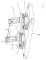
- Fig. 1 shows a first embodiment of the vibration cutting device 1 according to the present invention.
- the vibration cutting device 1 comprises a vibrating head 10 which is connected to a vibrating plate 15.
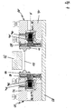
- the oscillating head 10, the example of Fig. 4 is explained in more detail, consists of a mass body and an electromagnetic drive.
- the electromagnetic drive of the oscillating head 10 is connected to a controller, so that with the oscillating head 10 specifically mechanical vibrations of a certain frequency range can be generated.
- This frequency range is between 50 and 500 Hz, ie below the ultrasonic range with frequencies in the kilohertz range.
- the oscillating head (s) of the vibratory cutting device 1 are controlled such that a cutting tool 50 is moved at a frequency of 50 to 500 Hz, preferably 50 to 60 Hz.
- the construction of the oscillating head 10 corresponds to that of the second oscillating head 70, which is arranged opposite the first oscillating head 10.
- the oscillating heads 10, 70 comprise a mass body 12, 72 and an electromagnetic drive 14, 74 consisting of an energizable coil arrangement 14a, 74a and a soft iron arrangement 14b, 74b, which lie on a common drive axis A. Between coil assembly 14a, 74a and soft iron assembly 14b, 74b is an air gap. By energizing the coil assembly 14a, 74a, the soft iron assembly 14b, 74b is vibrated.
- the soft iron arrangement 14b, 74b is connected to the holder 30, 40 for the cutting tool 50 via an optional spring assembly 60 (cf. Fig. 4 ).
- the soft iron assembly (not shown) is connected to the holder 30, 40, while the holder 30, 40 are resiliently mounted on the bridge body 80 via the spring packs 60.
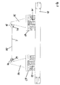
- the spring assembly 60 for example, from plate spring-like spring washers (see. Fig. 4 ) or from a comb-like spring construction according to Fig. 2 , Structure and operation of the vibrating heads 10, 70 described above are also in the DE 10 2006 011 974 and the EP 1 772 253 described.
- the cutting tool 50 is fixed to the first 30 and second bracket 40.
- the brackets 30, 40 are each vibrated by a vibrating head 10, 70 or only by one or more common oscillating heads. It is likewise conceivable to oscillate only one end of the cutting tool 50 or only one holder 30 by coupling to a vibrating head 10.
- the other end of the cutting tool 50 and / or the other holder 40 is resilient, for example.
- a spring assembly and / or mounted in a plain bearing to assist the movements of the cutting tool 50.
- the simplest embodiment of the vibratory cutting device 1 would consist of a spring assembly arranged at one end of the cutting tool 50, the Cutting tool 50 and a arranged at the other end of the cutting tool 50 oscillating head.
- the present vibration cutting device is set by these a plurality of cutting tools 50 in vibration.
- the plurality of cutting tools 50 serve to simultaneously make multiple cuts in the product to be cut. For example, it is conceivable to cut a cake into three parts at the same time with the aid of the vibration cutting device 50.
- two or three cutting tools 50 are attached to the first 30 and second holders 40 in the manner described above.
- the plurality of cutting tools 50 with respect to the cutting direction by the product to be cut offset from one another perpendicular to each other, that is arranged at a certain distance. This distance between the cutting tools 50 defines, for example, the thickness of a layer to be cut out of the product to be cut.
- these are preferably also offset parallel to the cutting direction by the product to be cut offset from one another. Based on this arrangement, it is ensured that the cutting tools 50 successively cut the product to be cut. This prevents the material displaced during cutting from hindering the cutting operation of another cutting tool 50.
- the plurality of cutting tools 50 are offset in relation to each other both in height and in depth.
- the plurality or a part of the cutting tools 50 are not arranged parallel to one another. Angular orientations with respect to one another are also conceivable with respect to the longitudinal axes of the cutting tools 50 in order to achieve specific cutting patterns in the product to be cut.
- the first 30 and second holder 40 are equipped with a clamping device 34, 44 and a clamping device 32, 42 for the cutting tool 50 (see. Fig. 1 . 2 ).
- the clamping device 34, 44 ensures a precise holding and guiding of the cutting tool 50.
- the clamping device 32, 42 allows a biasing and / or retightening of the cutting tool 50.
- the design and necessity of the clamping-34, 44 and clamping device 32, 42 is dependent on the shape and use of the cutting tool 50.
- the cutting tool 50 is formed according to various embodiments by a smooth blade, a toothed blade, a wave-profiled blade, a wire or a rope.
- the cutting tool 50 is about 10 to 150 cm long, preferably 30 to 100 cm.
- the vibrations generated by one or a plurality of oscillating heads 10, 70 are transmitted via the holders 30, 40 to the cutting tool 50 in such a way that the cutting tool 50 is deflected in the direction of its longitudinal axis.
- the oscillations performed by the cutting tool 50 in this way parallel to its longitudinal axis are predetermined in frequency and amplitude by the control of the oscillating heads 10, 70.
- the cutting tool 50 oscillates with amplitudes in the range of 5 to -5 mm. This amplitude range corresponds to the dimensions of, for example, a tooth structure of a toothed blade, so that the tooth structure is moved sawing in the product to be cut.
- the intersecting reciprocating motions and geometry of the cutting tool 50 such as saw teeth, complement each other to achieve optimum cutting action.
- an electrical voltage is applied to the respective coil arrangement 14a, 74a.
- This electrical voltage generates in the coil assembly 14a, 74a an electromagnetic force, which seeks to pull the soft iron assembly 14b, 74b and thus the holder 30, 40 against the restoring force of the spring assemblies 60 toward the coil assembly 14a, 74a.
- the restoring force of the spring assemblies 60 moves the soft iron assembly 14b, 74b and thus the holder 30, 40 back to the rest position.
- energy stored in the spring packs 60 is converted into a movement of the soft iron arrangement 14b, 74b and thus of the holders 30, 40 beyond their rest position.
- the oscillating head 10, 70 operates particularly effectively when the operating frequency for the electrical control of the electromagnetic drive 14, 74 is that frequency which corresponds to the mechanical resonance frequency of the vibratory cutting device 1.
- the mechanical resonance frequency results essentially from the spring rate of the spring assemblies 60 and the involved oscillating masses of the oscillating heads 10, 70.
- 74 corresponds to the electrical resonance frequency of half the mechanical resonance frequency.
- the at least two oscillating heads 10, 70 are not only connected mechanically via the cutting tool 50, but also via the bridge body 80.
- the bridge body 80 connects the mass bodies of the vibrating heads 10, 70 so as to form a unitary mass system.
- the coil assemblies 14a, 74a of the two oscillating heads 10, 70 are alternately electrically driven to produce harmonic vibration of the soft iron assemblies 14b, 74b, the brackets 30, 40, and the cutting tool 50.
- the spring assemblies 60 of the two oscillating heads 10, 70 are thus only needed to return the oscillating head 10, 70 to its rest position or with the oscillating masses for generating a mechanical resonance frequency.
- the deflections of the oscillating head 10, 70 from the rest position in both directions are generated by the two coil arrangements 14a, 74a, which are alternately electrically driven. In this way, a stable and reliable vibration cutting device 1 is provided, in which the cutting tool 50 performs a linear oscillation without superimposed vertical components.
- the bridge body 80 it is conceivable to use the bridge body 80 or omit it. If the bridge body 80 is omitted, the two oscillating heads 10, 70 are mechanically decoupled. A mechanical connection between the two oppositely arranged oscillating heads 10, 70 takes place only via the cutting tool 50. Since, in this embodiment, a common frequency of the oscillations of the two oscillating heads 10, 70 does not automatically occur, a must appropriate electrical coupling or common control of the two oscillating heads are provided. In this control, the frequency and the amplitude of the oscillations of the two oscillating heads 10, 70 are controlled so that the frequency of the two oscillating heads 10, 70 coincides and the amplitudes are in opposite phase.
- a vibratory cutting can thus be carried out, in which first at least one first oscillating head is excited to oscillate in a frequency range below the kilohertz range, preferably between 50 and 500 Hz.
- the excited vibrations are transmitted to the cutting tool 50 through the various constructions described.
- a work table 90 see. Fig. 4
- the product is cut due to the vibrations of the cutting tool 50.
- the mechanical and / or electrical couplings described above are used within the vibration cutting device 1.
- the work table 90 can move parallel to the cutting direction, preferably in all three spatial directions, to make the desired cut, it is also preferred that the cutting tool 50 be moved while the work table 90 is fixedly installed.
- the vibration cutting device 1 is arranged such that it is movable at least in the cutting direction, preferably in all three spatial directions. In this way, any cuts in a product to be cut can be realized. It is too it is conceivable to carry out the movement of work table 90 and / or vibration cutting device 1 in a computer-controlled manner in order to carry out a specific cut. On this basis, both cutting duration, cutting speed and cutting profile can be specified, changeable during cutting and optimally adaptable to different materials to be cut.
- the work table 90 is adjustable only for positioning in two spatial directions, it would be sufficient if the vibration cutting device 1 were movable only in the third remaining spatial direction for cutting. In this way, the degrees of freedom in the movement would be arbitrarily divisible on worktable 90 and vibration cutting device 1.
- the cutting tool 50 in an amplitude range of ⁇ 1 to 10 mm, preferably ⁇ 1 to 5 mm, parallel to its longitudinal axis deflected. In combination or alone, it is also preferable to oscillate the cutting tool 50 at a frequency of 50 to 60 Hz.
Landscapes
- Life Sciences & Earth Sciences (AREA)
- Forests & Forestry (AREA)
- Engineering & Computer Science (AREA)
- Mechanical Engineering (AREA)
- Turning (AREA)
- Perforating, Stamping-Out Or Severing By Means Other Than Cutting (AREA)
- Cutting Tools, Boring Holders, And Turrets (AREA)
Applications Claiming Priority (1)
| Application Number | Priority Date | Filing Date | Title |
|---|---|---|---|
| DE200710057468 DE102007057468B4 (de) | 2007-11-29 | 2007-11-29 | Vibrationsschneidvorrichtung und ein Verfahren zum Vibrationsschneiden |
Publications (2)
| Publication Number | Publication Date |
|---|---|
| EP2065146A1 true EP2065146A1 (fr) | 2009-06-03 |
| EP2065146B1 EP2065146B1 (fr) | 2015-08-26 |
Family
ID=40344786
Family Applications (1)
| Application Number | Title | Priority Date | Filing Date |
|---|---|---|---|
| EP08020238.5A Not-in-force EP2065146B1 (fr) | 2007-11-29 | 2008-11-20 | Dispositif de coupe à vibrations et procédé destiné à la coupe à vibrations |
Country Status (6)
| Country | Link |
|---|---|
| US (1) | US20100288092A1 (fr) |
| EP (1) | EP2065146B1 (fr) |
| JP (1) | JP5442629B2 (fr) |
| CN (1) | CN101909834B (fr) |
| DE (1) | DE102007057468B4 (fr) |
| WO (1) | WO2009068293A1 (fr) |
Cited By (3)
| Publication number | Priority date | Publication date | Assignee | Title |
|---|---|---|---|---|
| EP2554344A1 (fr) * | 2010-08-04 | 2013-02-06 | Deutsches Institut für Lebensmitteltechnik e.V. | Dispositif et procédé pour tenir des denrées alimentaires |
| CN106363683A (zh) * | 2016-09-20 | 2017-02-01 | 深圳市玖品空气净化科技有限公司 | 一种钢线切割装置 |
| FR3057195A1 (fr) * | 2016-10-11 | 2018-04-13 | Sodeva Tds | Dispositif de mise en vibration par ultrasons d’un fil vibrant pour la decoupe de produits industriels, et notamment des produits alimentaires |
Families Citing this family (11)
| Publication number | Priority date | Publication date | Assignee | Title |
|---|---|---|---|---|
| EP2551077A1 (fr) * | 2011-07-26 | 2013-01-30 | A O Schallinox GmbH | Couteau de répartition de produits de processus en utilisant l'énergie à ultrasons et dispositif |
| CN102284970B (zh) * | 2011-08-02 | 2013-03-13 | 浙江大学 | 非金属材料多丝线切割用的旋转超声换能器 |
| DE202013003438U1 (de) | 2013-04-12 | 2013-05-07 | Food Technology Thielemann Ohg | Vorrichtung zum Schneiden von Lebensmitteln, insbesondere Hochleistungs-Slicer |
| EP2803455A1 (fr) * | 2013-05-13 | 2014-11-19 | A O Schallinox GmbH | Dispositif de coupe d'un produit de processus |
| US10252441B2 (en) | 2013-08-28 | 2019-04-09 | Corning Incorporated | System and method for cutting a wet green ceramic article |
| CN107873925A (zh) * | 2017-12-28 | 2018-04-06 | 安徽盼盼食品有限公司 | 一种巧克力切割装置 |
| CN107980834A (zh) * | 2017-12-28 | 2018-05-04 | 安徽盼盼食品有限公司 | 一种用于切割糕点的装置 |
| JP7070311B2 (ja) * | 2018-10-10 | 2022-05-18 | 株式会社デンソー | 切断装置 |
| DE102019100808A1 (de) * | 2018-12-21 | 2020-06-25 | Weber Maschinenbau Gmbh Breidenbach | Käseteiler, Würfelschneider und Verfahren zum Schneiden eines Käseproduktes |
| EP3725500B1 (fr) | 2019-04-16 | 2023-07-12 | Branson Ultraschall Niederlassung der Emerson Technologies GmbH & Co. oHG | Bloc-ressort pour dispositif de soudage par vibrations et dispositif de soudage par vibrations respectif |
| WO2022254621A1 (fr) * | 2021-06-02 | 2022-12-08 | 三菱電機株式会社 | Dispositif de commande numérique, dispositif d'apprentissage, dispositif d'inférence et procédé de commande numérique |
Citations (7)
| Publication number | Priority date | Publication date | Assignee | Title |
|---|---|---|---|---|
| FR2622140A1 (fr) * | 1987-10-27 | 1989-04-28 | Majer Mihaly | Dispositif pour decouper des materiaux |
| DE19511964A1 (de) * | 1995-03-31 | 1996-10-10 | Mertes Gmbh Anneliese | Schneidgerät |
| DE19537826C1 (de) * | 1995-10-11 | 1997-02-27 | Wolf Und Partner Ingenieurbuer | Ultraschallerregtes Schneidsystem, insbesondere zum Schneiden von Lebensmitteln |
| DE29801500U1 (de) * | 1998-01-30 | 1999-06-02 | Kurtz Altaussee Gmbh, Altaussee | Schneidrahmen zum Schneiden von insbesondere durch Erhitzen schneidbarem Material |
| DE10314444A1 (de) * | 2003-03-31 | 2004-10-14 | Robert Bosch Gmbh | Einrichtung zum Schneiden eines Produkts |
| EP1772253A2 (fr) | 2005-10-05 | 2007-04-11 | BRANSON ULTRASCHALL Niederlassung der EMERSON TECHNOLOGIES GmbH & CO. | Dispositif et procédé de soudage par vibration |
| DE102006011974A1 (de) | 2006-03-15 | 2007-09-20 | Siemens Ag | Verfahren zum Transportieren von Werkstückträgern in einer Montagelinie, Werkstückträger und Montageeinheit |
Family Cites Families (24)
| Publication number | Priority date | Publication date | Assignee | Title |
|---|---|---|---|---|
| US2384435A (en) * | 1945-09-11 | Fortable cutting tool | ||
| US2714890A (en) * | 1953-08-06 | 1955-08-09 | Vang Alfred | Vibratory surgical instruments |
| US3664021A (en) * | 1969-10-30 | 1972-05-23 | Vernon D Beeler | Knife |
| US4188952A (en) * | 1973-12-28 | 1980-02-19 | Loschilov Vladimir I | Surgical instrument for ultrasonic separation of biological tissue |
| JPS5459385A (en) * | 1977-10-19 | 1979-05-12 | Ezaki Tetsukoushiyo Kk | Cake cutter |
| JPS5664925A (en) * | 1979-11-01 | 1981-06-02 | Haito Kk | Method and device for dividing body cut into thin piece |
| EP0148250A1 (fr) * | 1983-07-06 | 1985-07-17 | STASZ, Peter | Couteau chirurgical pour electro-cauterisation |
| JPS6127699U (ja) * | 1984-07-24 | 1986-02-19 | 山崎製パン株式会社 | 食品類の切断装置 |
| JPS62166997A (ja) * | 1986-01-14 | 1987-07-23 | 株式会社新潟鐵工所 | ケ−キ等の切断装置 |
| NL8700271A (nl) * | 1987-02-04 | 1988-09-01 | Durox Gasbeton Bv | Werkwijze en inrichting voor het snijden van gasbeton. |
| US5341054A (en) * | 1988-08-31 | 1994-08-23 | Aura Systems, Inc. | Low mass electromagnetic actuator |
| JPH02116498A (ja) * | 1988-10-25 | 1990-05-01 | Toshiba Corp | 切断装置 |
| JPH07100317B2 (ja) * | 1990-03-07 | 1995-11-01 | 株式会社カイジョー | パン類、蓄肉加工品等の超音波切断装置及び切断装置 |
| CN1079315C (zh) * | 1996-03-26 | 2002-02-20 | 松下电工株式会社 | 往复式电动剃刀 |
| JP3128508B2 (ja) * | 1996-04-12 | 2001-01-29 | 株式会社アルテクス | 超音波振動カッター |
| NL1005537C2 (nl) * | 1997-03-14 | 1998-09-15 | Rompa Patent Beheer B V | Inrichting voor het in plakken snijden van broden en dergelijke bakkerijprodukten. |
| JP2001105390A (ja) * | 1999-10-08 | 2001-04-17 | Kaijo Corp | 唸り防止機構を備えた超音波カッター装置 |
| DE10045890A1 (de) * | 2000-09-16 | 2002-04-04 | Bosch Gmbh Robert | Säge mit einem Werkzeugführungsmechanismus |
| JP3486396B2 (ja) * | 2000-10-10 | 2004-01-13 | 株式会社ユーハイム | ケーキ等の切断装置 |
| US6514267B2 (en) * | 2001-03-26 | 2003-02-04 | Iep Pharmaceutical Devices Inc. | Ultrasonic scalpel |
| JP2003061713A (ja) * | 2001-08-27 | 2003-03-04 | Kuraray Co Ltd | 面ファスナー用フィラメントループ部材の切断装置 |
| JP2003231089A (ja) * | 2002-02-07 | 2003-08-19 | Nippon Alex Kk | 超音波切断用共振器 |
| US20050081692A1 (en) * | 2003-10-20 | 2005-04-21 | Kraft Foods Holdings, Inc. | Ultrasonic slitter |
| CN1915614B (zh) * | 2006-09-01 | 2011-05-25 | 东莞市恒生机械制造有限公司 | 刀头震动式切割海绵机构 |
-
2007
- 2007-11-29 DE DE200710057468 patent/DE102007057468B4/de not_active Expired - Fee Related
-
2008
- 2008-11-20 EP EP08020238.5A patent/EP2065146B1/fr not_active Not-in-force
- 2008-11-27 JP JP2010535292A patent/JP5442629B2/ja not_active Expired - Fee Related
- 2008-11-27 CN CN200880124500.9A patent/CN101909834B/zh not_active Expired - Fee Related
- 2008-11-27 WO PCT/EP2008/010091 patent/WO2009068293A1/fr not_active Ceased
- 2008-11-27 US US12/744,101 patent/US20100288092A1/en not_active Abandoned
Patent Citations (7)
| Publication number | Priority date | Publication date | Assignee | Title |
|---|---|---|---|---|
| FR2622140A1 (fr) * | 1987-10-27 | 1989-04-28 | Majer Mihaly | Dispositif pour decouper des materiaux |
| DE19511964A1 (de) * | 1995-03-31 | 1996-10-10 | Mertes Gmbh Anneliese | Schneidgerät |
| DE19537826C1 (de) * | 1995-10-11 | 1997-02-27 | Wolf Und Partner Ingenieurbuer | Ultraschallerregtes Schneidsystem, insbesondere zum Schneiden von Lebensmitteln |
| DE29801500U1 (de) * | 1998-01-30 | 1999-06-02 | Kurtz Altaussee Gmbh, Altaussee | Schneidrahmen zum Schneiden von insbesondere durch Erhitzen schneidbarem Material |
| DE10314444A1 (de) * | 2003-03-31 | 2004-10-14 | Robert Bosch Gmbh | Einrichtung zum Schneiden eines Produkts |
| EP1772253A2 (fr) | 2005-10-05 | 2007-04-11 | BRANSON ULTRASCHALL Niederlassung der EMERSON TECHNOLOGIES GmbH & CO. | Dispositif et procédé de soudage par vibration |
| DE102006011974A1 (de) | 2006-03-15 | 2007-09-20 | Siemens Ag | Verfahren zum Transportieren von Werkstückträgern in einer Montagelinie, Werkstückträger und Montageeinheit |
Cited By (4)
| Publication number | Priority date | Publication date | Assignee | Title |
|---|---|---|---|---|
| EP2554344A1 (fr) * | 2010-08-04 | 2013-02-06 | Deutsches Institut für Lebensmitteltechnik e.V. | Dispositif et procédé pour tenir des denrées alimentaires |
| CN106363683A (zh) * | 2016-09-20 | 2017-02-01 | 深圳市玖品空气净化科技有限公司 | 一种钢线切割装置 |
| CN106363683B (zh) * | 2016-09-20 | 2018-08-10 | 山西天祥机械有限公司 | 一种钢线切割装置 |
| FR3057195A1 (fr) * | 2016-10-11 | 2018-04-13 | Sodeva Tds | Dispositif de mise en vibration par ultrasons d’un fil vibrant pour la decoupe de produits industriels, et notamment des produits alimentaires |
Also Published As
| Publication number | Publication date |
|---|---|
| JP5442629B2 (ja) | 2014-03-12 |
| DE102007057468B4 (de) | 2012-10-04 |
| WO2009068293A1 (fr) | 2009-06-04 |
| DE102007057468A1 (de) | 2009-06-10 |
| US20100288092A1 (en) | 2010-11-18 |
| JP2011504816A (ja) | 2011-02-17 |
| CN101909834B (zh) | 2015-06-17 |
| EP2065146B1 (fr) | 2015-08-26 |
| CN101909834A (zh) | 2010-12-08 |
Similar Documents
| Publication | Publication Date | Title |
|---|---|---|
| EP2065146B1 (fr) | Dispositif de coupe à vibrations et procédé destiné à la coupe à vibrations | |
| DE2721804A1 (de) | Verfahren und vorrichtung zur elektroerosiven bearbeitung | |
| EP2768403B1 (fr) | Sonotrode | |
| DE2532029A1 (de) | Verfahren zur beaufschlagung einer fluessigkeit mit hochfrequenter schallenergie und vorrichtung zur durchfuehrung des verfahrens | |
| DE102013100474A1 (de) | Ultraschallschweißvorrichtung mit schwingungsentkoppeltem Gegenwerkzeug | |
| EP3389912B1 (fr) | Machine de soudage par friction linéaire | |
| DE4223645A1 (de) | Vibrations-bearbeitungsverfahren und schneidvorrichtung zu seiner durchfuehrung | |
| EP2655006A1 (fr) | Dispositif à deux composantes d'oscillation pour l'usinage par enlèvement de copeaux d'une pièce | |
| DE102007016353B4 (de) | Schwingungs-Koppeleinheit | |
| DE1289344B (de) | Arbeitsschwinger | |
| DE4408618B4 (de) | Verstellantrieb aus Bimorphelementen | |
| EP3556540B1 (fr) | Dispositif de soudage par vibrations, procédé de raccordement d'au moins deux pièces de construction allongées au moyen d'un soudage par vibrations ainsi que procédé de fabrication du dispositif de soudage par vibrations | |
| DE19947104C2 (de) | Verfahren und Einrichtung zum Laserschweißen | |
| EP2739428B1 (fr) | Procédé et dispositif d'assemblage par ultrasons au moyen d'au moins un premier et un deuxième transducteur ultrasonique générant des parties d'oscillations harmoniques | |
| DE2047883A1 (de) | Schwingungsubertrager fur Ultraschall | |
| CH676586A5 (fr) | ||
| DE102020208876A1 (de) | Aktor, Werkzeugmaschine und Verfahren zum spanenden Bearbeiten | |
| DE19951288A1 (de) | Präzisionsschwingungsantrieb | |
| EP1834754A2 (fr) | Installation de soudure par vibrations et sa tête vibrante | |
| WO2012095385A2 (fr) | Procédé et dispositif pour conférer un mouvement oscillant à une masse | |
| WO2002087459A2 (fr) | Piece a main conçue pour une commande lineaire, en particulier d'un instrument dentaire | |
| DE102006020429A1 (de) | Vorrichtung zum Bearbeiten von Werkstücken mittels Ultraschall sowie Verfahren zum Betreiben einer derartigen Vorrichtung | |
| EP1514652A2 (fr) | Dispositif pour la coupe de produits alimentaires ayant un moyen de coupe comprenant un générateur de vibrations | |
| EP1917127B1 (fr) | Dispositif pour decouper des produits alimentaires | |
| DE10314444A1 (de) | Einrichtung zum Schneiden eines Produkts |
Legal Events
| Date | Code | Title | Description |
|---|---|---|---|
| PUAI | Public reference made under article 153(3) epc to a published international application that has entered the european phase |
Free format text: ORIGINAL CODE: 0009012 |
|
| AK | Designated contracting states |
Kind code of ref document: A1 Designated state(s): AT BE BG CH CY CZ DE DK EE ES FI FR GB GR HR HU IE IS IT LI LT LU LV MC MT NL NO PL PT RO SE SI SK TR |
|
| AX | Request for extension of the european patent |
Extension state: AL BA MK RS |
|
| 17P | Request for examination filed |
Effective date: 20091202 |
|
| AKX | Designation fees paid |
Designated state(s): AT BE BG CH CY CZ DE DK EE ES FI FR GB GR HR HU IE IS IT LI LT LU LV MC MT NL NO PL PT RO SE SI SK TR |
|
| 17Q | First examination report despatched |
Effective date: 20110419 |
|
| GRAP | Despatch of communication of intention to grant a patent |
Free format text: ORIGINAL CODE: EPIDOSNIGR1 |
|
| INTG | Intention to grant announced |
Effective date: 20150319 |
|
| RAP1 | Party data changed (applicant data changed or rights of an application transferred) |
Owner name: BRANSON ULTRASCHALL NIEDERLASSUNG DER EMERSON TECH |
|
| GRAS | Grant fee paid |
Free format text: ORIGINAL CODE: EPIDOSNIGR3 |
|
| GRAA | (expected) grant |
Free format text: ORIGINAL CODE: 0009210 |
|
| AK | Designated contracting states |
Kind code of ref document: B1 Designated state(s): AT BE BG CH CY CZ DE DK EE ES FI FR GB GR HR HU IE IS IT LI LT LU LV MC MT NL NO PL PT RO SE SI SK TR |
|
| REG | Reference to a national code |
Ref country code: GB Ref legal event code: FG4D Free format text: NOT ENGLISH |
|
| REG | Reference to a national code |
Ref country code: CH Ref legal event code: EP |
|
| REG | Reference to a national code |
Ref country code: AT Ref legal event code: REF Ref document number: 744898 Country of ref document: AT Kind code of ref document: T Effective date: 20150915 |
|
| REG | Reference to a national code |
Ref country code: IE Ref legal event code: FG4D Free format text: LANGUAGE OF EP DOCUMENT: GERMAN |
|
| REG | Reference to a national code |
Ref country code: DE Ref legal event code: R096 Ref document number: 502008013304 Country of ref document: DE |
|
| REG | Reference to a national code |
Ref country code: FR Ref legal event code: PLFP Year of fee payment: 8 |
|
| REG | Reference to a national code |
Ref country code: LT Ref legal event code: MG4D |
|
| PG25 | Lapsed in a contracting state [announced via postgrant information from national office to epo] |
Ref country code: LV Free format text: LAPSE BECAUSE OF FAILURE TO SUBMIT A TRANSLATION OF THE DESCRIPTION OR TO PAY THE FEE WITHIN THE PRESCRIBED TIME-LIMIT Effective date: 20150826 Ref country code: NO Free format text: LAPSE BECAUSE OF FAILURE TO SUBMIT A TRANSLATION OF THE DESCRIPTION OR TO PAY THE FEE WITHIN THE PRESCRIBED TIME-LIMIT Effective date: 20151126 Ref country code: GR Free format text: LAPSE BECAUSE OF FAILURE TO SUBMIT A TRANSLATION OF THE DESCRIPTION OR TO PAY THE FEE WITHIN THE PRESCRIBED TIME-LIMIT Effective date: 20151127 Ref country code: LT Free format text: LAPSE BECAUSE OF FAILURE TO SUBMIT A TRANSLATION OF THE DESCRIPTION OR TO PAY THE FEE WITHIN THE PRESCRIBED TIME-LIMIT Effective date: 20150826 Ref country code: FI Free format text: LAPSE BECAUSE OF FAILURE TO SUBMIT A TRANSLATION OF THE DESCRIPTION OR TO PAY THE FEE WITHIN THE PRESCRIBED TIME-LIMIT Effective date: 20150826 |
|
| REG | Reference to a national code |
Ref country code: NL Ref legal event code: MP Effective date: 20150826 |
|
| PG25 | Lapsed in a contracting state [announced via postgrant information from national office to epo] |
Ref country code: IS Free format text: LAPSE BECAUSE OF FAILURE TO SUBMIT A TRANSLATION OF THE DESCRIPTION OR TO PAY THE FEE WITHIN THE PRESCRIBED TIME-LIMIT Effective date: 20151226 Ref country code: ES Free format text: LAPSE BECAUSE OF FAILURE TO SUBMIT A TRANSLATION OF THE DESCRIPTION OR TO PAY THE FEE WITHIN THE PRESCRIBED TIME-LIMIT Effective date: 20150826 Ref country code: PT Free format text: LAPSE BECAUSE OF FAILURE TO SUBMIT A TRANSLATION OF THE DESCRIPTION OR TO PAY THE FEE WITHIN THE PRESCRIBED TIME-LIMIT Effective date: 20151228 Ref country code: PL Free format text: LAPSE BECAUSE OF FAILURE TO SUBMIT A TRANSLATION OF THE DESCRIPTION OR TO PAY THE FEE WITHIN THE PRESCRIBED TIME-LIMIT Effective date: 20150826 Ref country code: SE Free format text: LAPSE BECAUSE OF FAILURE TO SUBMIT A TRANSLATION OF THE DESCRIPTION OR TO PAY THE FEE WITHIN THE PRESCRIBED TIME-LIMIT Effective date: 20150826 Ref country code: HR Free format text: LAPSE BECAUSE OF FAILURE TO SUBMIT A TRANSLATION OF THE DESCRIPTION OR TO PAY THE FEE WITHIN THE PRESCRIBED TIME-LIMIT Effective date: 20150826 |
|
| PG25 | Lapsed in a contracting state [announced via postgrant information from national office to epo] |
Ref country code: NL Free format text: LAPSE BECAUSE OF FAILURE TO SUBMIT A TRANSLATION OF THE DESCRIPTION OR TO PAY THE FEE WITHIN THE PRESCRIBED TIME-LIMIT Effective date: 20150826 |
|
| PG25 | Lapsed in a contracting state [announced via postgrant information from national office to epo] |
Ref country code: DK Free format text: LAPSE BECAUSE OF FAILURE TO SUBMIT A TRANSLATION OF THE DESCRIPTION OR TO PAY THE FEE WITHIN THE PRESCRIBED TIME-LIMIT Effective date: 20150826 Ref country code: EE Free format text: LAPSE BECAUSE OF FAILURE TO SUBMIT A TRANSLATION OF THE DESCRIPTION OR TO PAY THE FEE WITHIN THE PRESCRIBED TIME-LIMIT Effective date: 20150826 Ref country code: SK Free format text: LAPSE BECAUSE OF FAILURE TO SUBMIT A TRANSLATION OF THE DESCRIPTION OR TO PAY THE FEE WITHIN THE PRESCRIBED TIME-LIMIT Effective date: 20150826 Ref country code: CZ Free format text: LAPSE BECAUSE OF FAILURE TO SUBMIT A TRANSLATION OF THE DESCRIPTION OR TO PAY THE FEE WITHIN THE PRESCRIBED TIME-LIMIT Effective date: 20150826 |
|
| REG | Reference to a national code |
Ref country code: DE Ref legal event code: R097 Ref document number: 502008013304 Country of ref document: DE |
|
| PG25 | Lapsed in a contracting state [announced via postgrant information from national office to epo] |
Ref country code: RO Free format text: LAPSE BECAUSE OF FAILURE TO SUBMIT A TRANSLATION OF THE DESCRIPTION OR TO PAY THE FEE WITHIN THE PRESCRIBED TIME-LIMIT Effective date: 20150826 |
|
| PG25 | Lapsed in a contracting state [announced via postgrant information from national office to epo] |
Ref country code: MC Free format text: LAPSE BECAUSE OF FAILURE TO SUBMIT A TRANSLATION OF THE DESCRIPTION OR TO PAY THE FEE WITHIN THE PRESCRIBED TIME-LIMIT Effective date: 20150826 Ref country code: LU Free format text: LAPSE BECAUSE OF FAILURE TO SUBMIT A TRANSLATION OF THE DESCRIPTION OR TO PAY THE FEE WITHIN THE PRESCRIBED TIME-LIMIT Effective date: 20151120 |
|
| PLBE | No opposition filed within time limit |
Free format text: ORIGINAL CODE: 0009261 |
|
| STAA | Information on the status of an ep patent application or granted ep patent |
Free format text: STATUS: NO OPPOSITION FILED WITHIN TIME LIMIT |
|
| 26N | No opposition filed |
Effective date: 20160530 |
|
| REG | Reference to a national code |
Ref country code: IE Ref legal event code: MM4A |
|
| PG25 | Lapsed in a contracting state [announced via postgrant information from national office to epo] |
Ref country code: SI Free format text: LAPSE BECAUSE OF FAILURE TO SUBMIT A TRANSLATION OF THE DESCRIPTION OR TO PAY THE FEE WITHIN THE PRESCRIBED TIME-LIMIT Effective date: 20150826 |
|
| PG25 | Lapsed in a contracting state [announced via postgrant information from national office to epo] |
Ref country code: IE Free format text: LAPSE BECAUSE OF NON-PAYMENT OF DUE FEES Effective date: 20151120 |
|
| REG | Reference to a national code |
Ref country code: FR Ref legal event code: PLFP Year of fee payment: 9 |
|
| REG | Reference to a national code |
Ref country code: AT Ref legal event code: MM01 Ref document number: 744898 Country of ref document: AT Kind code of ref document: T Effective date: 20151120 |
|
| PGFP | Annual fee paid to national office [announced via postgrant information from national office to epo] |
Ref country code: GB Payment date: 20161124 Year of fee payment: 9 Ref country code: FR Payment date: 20161124 Year of fee payment: 9 |
|
| PG25 | Lapsed in a contracting state [announced via postgrant information from national office to epo] |
Ref country code: AT Free format text: LAPSE BECAUSE OF NON-PAYMENT OF DUE FEES Effective date: 20151120 |
|
| PGFP | Annual fee paid to national office [announced via postgrant information from national office to epo] |
Ref country code: IT Payment date: 20161124 Year of fee payment: 9 |
|
| PG25 | Lapsed in a contracting state [announced via postgrant information from national office to epo] |
Ref country code: BG Free format text: LAPSE BECAUSE OF FAILURE TO SUBMIT A TRANSLATION OF THE DESCRIPTION OR TO PAY THE FEE WITHIN THE PRESCRIBED TIME-LIMIT Effective date: 20150826 Ref country code: HU Free format text: LAPSE BECAUSE OF FAILURE TO SUBMIT A TRANSLATION OF THE DESCRIPTION OR TO PAY THE FEE WITHIN THE PRESCRIBED TIME-LIMIT; INVALID AB INITIO Effective date: 20081120 |
|
| PG25 | Lapsed in a contracting state [announced via postgrant information from national office to epo] |
Ref country code: CY Free format text: LAPSE BECAUSE OF FAILURE TO SUBMIT A TRANSLATION OF THE DESCRIPTION OR TO PAY THE FEE WITHIN THE PRESCRIBED TIME-LIMIT Effective date: 20150826 |
|
| PG25 | Lapsed in a contracting state [announced via postgrant information from national office to epo] |
Ref country code: BE Free format text: LAPSE BECAUSE OF NON-PAYMENT OF DUE FEES Effective date: 20151130 |
|
| PG25 | Lapsed in a contracting state [announced via postgrant information from national office to epo] |
Ref country code: TR Free format text: LAPSE BECAUSE OF FAILURE TO SUBMIT A TRANSLATION OF THE DESCRIPTION OR TO PAY THE FEE WITHIN THE PRESCRIBED TIME-LIMIT Effective date: 20150826 Ref country code: MT Free format text: LAPSE BECAUSE OF FAILURE TO SUBMIT A TRANSLATION OF THE DESCRIPTION OR TO PAY THE FEE WITHIN THE PRESCRIBED TIME-LIMIT Effective date: 20150826 |
|
| GBPC | Gb: european patent ceased through non-payment of renewal fee |
Effective date: 20171120 |
|
| REG | Reference to a national code |
Ref country code: FR Ref legal event code: ST Effective date: 20180731 |
|
| PG25 | Lapsed in a contracting state [announced via postgrant information from national office to epo] |
Ref country code: IT Free format text: LAPSE BECAUSE OF NON-PAYMENT OF DUE FEES Effective date: 20171120 Ref country code: FR Free format text: LAPSE BECAUSE OF NON-PAYMENT OF DUE FEES Effective date: 20171130 |
|
| PG25 | Lapsed in a contracting state [announced via postgrant information from national office to epo] |
Ref country code: GB Free format text: LAPSE BECAUSE OF NON-PAYMENT OF DUE FEES Effective date: 20171120 |
|
| PGFP | Annual fee paid to national office [announced via postgrant information from national office to epo] |
Ref country code: CH Payment date: 20181204 Year of fee payment: 11 |
|
| PGFP | Annual fee paid to national office [announced via postgrant information from national office to epo] |
Ref country code: DE Payment date: 20200122 Year of fee payment: 12 |
|
| REG | Reference to a national code |
Ref country code: CH Ref legal event code: PL |
|
| PG25 | Lapsed in a contracting state [announced via postgrant information from national office to epo] |
Ref country code: CH Free format text: LAPSE BECAUSE OF NON-PAYMENT OF DUE FEES Effective date: 20191130 Ref country code: LI Free format text: LAPSE BECAUSE OF NON-PAYMENT OF DUE FEES Effective date: 20191130 |
|
| REG | Reference to a national code |
Ref country code: DE Ref legal event code: R119 Ref document number: 502008013304 Country of ref document: DE |
|
| PG25 | Lapsed in a contracting state [announced via postgrant information from national office to epo] |
Ref country code: DE Free format text: LAPSE BECAUSE OF NON-PAYMENT OF DUE FEES Effective date: 20210601 |