EP2065149A1 - Procédé et dispositif destinés au marquage d'une pile d'éléments de type plaques, pile dotée d'un marquage ainsi qu'élément de type plaque - Google Patents
Procédé et dispositif destinés au marquage d'une pile d'éléments de type plaques, pile dotée d'un marquage ainsi qu'élément de type plaque Download PDFInfo
- Publication number
- EP2065149A1 EP2065149A1 EP08105709A EP08105709A EP2065149A1 EP 2065149 A1 EP2065149 A1 EP 2065149A1 EP 08105709 A EP08105709 A EP 08105709A EP 08105709 A EP08105709 A EP 08105709A EP 2065149 A1 EP2065149 A1 EP 2065149A1
- Authority
- EP
- European Patent Office
- Prior art keywords
- stack
- plate
- marking
- elements
- mark
- Prior art date
- Legal status (The legal status is an assumption and is not a legal conclusion. Google has not performed a legal analysis and makes no representation as to the accuracy of the status listed.)
- Granted
Links
- 238000000034 method Methods 0.000 title claims abstract description 51
- 239000003550 marker Substances 0.000 claims abstract description 14
- 238000004519 manufacturing process Methods 0.000 claims description 11
- 239000000463 material Substances 0.000 claims description 11
- 239000002023 wood Substances 0.000 claims description 8
- 238000003754 machining Methods 0.000 claims description 6
- 238000002604 ultrasonography Methods 0.000 claims description 6
- 238000004806 packaging method and process Methods 0.000 claims description 5
- 238000003801 milling Methods 0.000 claims description 4
- 208000029154 Narrow face Diseases 0.000 claims 1
- 230000005693 optoelectronics Effects 0.000 abstract description 4
- 230000001070 adhesive effect Effects 0.000 description 17
- 239000000853 adhesive Substances 0.000 description 16
- WSFSSNUMVMOOMR-UHFFFAOYSA-N Formaldehyde Chemical compound O=C WSFSSNUMVMOOMR-UHFFFAOYSA-N 0.000 description 3
- 230000006735 deficit Effects 0.000 description 3
- 239000002657 fibrous material Substances 0.000 description 3
- 239000007789 gas Substances 0.000 description 3
- 238000004904 shortening Methods 0.000 description 3
- 238000005034 decoration Methods 0.000 description 2
- 238000001514 detection method Methods 0.000 description 2
- 239000004033 plastic Substances 0.000 description 2
- 208000036829 Device dislocation Diseases 0.000 description 1
- 239000011230 binding agent Substances 0.000 description 1
- 239000011093 chipboard Substances 0.000 description 1
- 239000003086 colorant Substances 0.000 description 1
- 230000001419 dependent effect Effects 0.000 description 1
- 238000001035 drying Methods 0.000 description 1
- 230000000694 effects Effects 0.000 description 1
- 239000011094 fiberboard Substances 0.000 description 1
- 238000007373 indentation Methods 0.000 description 1
- 238000002372 labelling Methods 0.000 description 1
- 239000002184 metal Substances 0.000 description 1
- 239000000203 mixture Substances 0.000 description 1
- 230000001473 noxious effect Effects 0.000 description 1
Images




Classifications
-
- B—PERFORMING OPERATIONS; TRANSPORTING
- B27—WORKING OR PRESERVING WOOD OR SIMILAR MATERIAL; NAILING OR STAPLING MACHINES IN GENERAL
- B27M—WORKING OF WOOD NOT PROVIDED FOR IN SUBCLASSES B27B - B27L; MANUFACTURE OF SPECIFIC WOODEN ARTICLES
- B27M1/00—Working of wood not provided for in subclasses B27B - B27L, e.g. by stretching
-
- B—PERFORMING OPERATIONS; TRANSPORTING
- B41—PRINTING; LINING MACHINES; TYPEWRITERS; STAMPS
- B41J—TYPEWRITERS; SELECTIVE PRINTING MECHANISMS, i.e. MECHANISMS PRINTING OTHERWISE THAN FROM A FORME; CORRECTION OF TYPOGRAPHICAL ERRORS
- B41J3/00—Typewriters or selective printing or marking mechanisms characterised by the purpose for which they are constructed
- B41J3/01—Typewriters or selective printing or marking mechanisms characterised by the purpose for which they are constructed for special character, e.g. for Chinese characters or barcodes
-
- B—PERFORMING OPERATIONS; TRANSPORTING
- B41—PRINTING; LINING MACHINES; TYPEWRITERS; STAMPS
- B41J—TYPEWRITERS; SELECTIVE PRINTING MECHANISMS, i.e. MECHANISMS PRINTING OTHERWISE THAN FROM A FORME; CORRECTION OF TYPOGRAPHICAL ERRORS
- B41J3/00—Typewriters or selective printing or marking mechanisms characterised by the purpose for which they are constructed
- B41J3/407—Typewriters or selective printing or marking mechanisms characterised by the purpose for which they are constructed for marking on special material
-
- B—PERFORMING OPERATIONS; TRANSPORTING
- B41—PRINTING; LINING MACHINES; TYPEWRITERS; STAMPS
- B41M—PRINTING, DUPLICATING, MARKING, OR COPYING PROCESSES; COLOUR PRINTING
- B41M1/00—Inking and printing with a printer's forme
- B41M1/40—Printing on bodies of particular shapes, e.g. golf balls, candles, wine corks
-
- B—PERFORMING OPERATIONS; TRANSPORTING
- B41—PRINTING; LINING MACHINES; TYPEWRITERS; STAMPS
- B41M—PRINTING, DUPLICATING, MARKING, OR COPYING PROCESSES; COLOUR PRINTING
- B41M5/00—Duplicating or marking methods; Sheet materials for use therein
- B41M5/0082—Digital printing on bodies of particular shapes
- B41M5/0088—Digital printing on bodies of particular shapes by ink-jet printing
-
- B—PERFORMING OPERATIONS; TRANSPORTING
- B41—PRINTING; LINING MACHINES; TYPEWRITERS; STAMPS
- B41M—PRINTING, DUPLICATING, MARKING, OR COPYING PROCESSES; COLOUR PRINTING
- B41M5/00—Duplicating or marking methods; Sheet materials for use therein
- B41M5/26—Thermography ; Marking by high energetic means, e.g. laser otherwise than by burning, and characterised by the material used
Definitions
- the invention relates to a method for marking a plate-like element. Furthermore, the invention relates to a device for marking a plate-like element with a stacking device which brings at least two plate-like elements in planar contact their major surfaces to each other to form a stack, and with an adjusting device, which aligns the plate-like elements so that at least the narrow surfaces of the plate-like elements to be provided with a mark, are in alignment. Furthermore, the invention relates to a stack having at least two plate-like elements arranged in planar contact with one another of their main surfaces, wherein the narrow surfaces of the individual plate-like elements form the side surfaces of the stack. Moreover, the invention relates to a plate-like element having at least one narrow surface, which has a thickness of less than 5 mm.
- plate-like elements such as plates made of wood or a wood material
- a marker which preferably has a characterizing character.
- the marking is intended, for example, to provide information about the characteristics of the plate-like element, the nature of it, where, when and by whom it was produced or for what purpose it is intended.
- an adhesive label can be printed with the desired information.
- all surfaces, ie the main surfaces and the narrow surfaces, of a plate-like element are suitable for applying the adhesive label.
- this type of marking has several disadvantages.
- the provision of an adhesive label as an additional carrier of the marking is costly.
- the application of adhesive labels on each plate-like element is associated with a high expenditure of time. It is possible that the adhesive labels, for example, in the case of insufficient adhesive effect or by external action, again loosen, whereby the marking would be lost.
- the adhesive labels are applied to a main surface of a plate-like element, they must be removed if necessary before use of the plate-like element in order to avoid an aesthetic impairment of the main surface, in particular the front. This is disadvantageous, for example, in the case of laminate-coated panels, since a specific, preferably aesthetically perfect, decor should usually be visible on the front side of the laminate.
- the stackability of plate-like members carrying an adhesive label on a main surface is limited.
- the Adhesive label formed an elevated area, which can lead to instabilities of the stack in a plurality of surface-mounted their major surfaces arranged plate-like elements by the so-reduced contact surface.
- a dead volume is created by the raised area, which increases the space requirement of the stack over the sum of the thicknesses of the individual plate-like elements addition.
- the application of an adhesive label on a narrow surface of a plate-like element is unfavorable, since there is only a very small application area available on a narrow surface.
- the application of an adhesive label on a narrow surface may be further complicated if the narrow surface has a profile.
- Procedures by which permanent, that is not removable, markings can be provided on a main surface are not preferred because they take a long time and are only useful if the aesthetic design of the Main surfaces, such as the front, for the use of the plate-like element is insignificant.
- Another way to mark a plate-like element is to apply the desired information in characters (letters, numbers, etc.), ie in plain text, on a narrow surface of a plate-like element.
- the reading direction of the plain text is preferably along the extension direction of the narrow surface on which the plain text is applied.
- this approach is practicable only if the plate-like member has a thickness sufficient for the application of plain text in readable size. This means, on the one hand, that the height of the characters must be smaller than the thickness of the plate-like element, and, on the other hand, that the characters are to be arranged transversely centered to the direction of extension of the narrow surface, in order to avoid impairments of the typeface.
- the present invention is therefore based on the technical problem of providing a method and a device, with which or with which plate-like elements of less Thickness provided with a mark and the aforementioned disadvantages can be avoided.
- the technical problem is solved by means of a method for marking a plate-like element, wherein from at least two plate-like elements by flat contact their major surfaces to each other a stack is formed and wherein the side surfaces of the stack of the narrow surfaces of the individual plate-like elements are formed, wherein at least one side surface of the stack is provided with at least one mark.
- a narrow area of small thickness of a plate-like element can be provided with a marking if at least two plate-like elements are arranged in planar contact of their main surfaces to each other, so that they form a stack, and a side surface of the stack, which consists of the individual narrow surfaces of the plate-like elements is formed, is provided with a marker.
- An additional marking carrier is not required. It can be exploited that a side surface of a stack provides a larger area for applying a mark than a narrow surface of a single plate-like element. The narrow surfaces of the individual plate-like elements therefore no longer need to be marked individually, which significantly reduces the time required for marking.
- a plurality of plate-like elements are first stacked and then with a Mark provided, for example, on the nature, texture, characteristics or manufacturing history of the plate-like elements information, and which is attached to a side surface of the stack of plate-like elements.
- the marking of the side surface of the stack as a whole and thus also the part of the marking arranged on the narrow surface of each individual plate-like element has the same information content.
- a side surface of the stack is provided with an optoelectronically detectable marking.
- this may be a bar code.
- the optoelectronically detectable marking is that the stack and possibly also the individual plate-like elements are better suited for processing in automated processes.
- a marking In order to improve the opto-electronic detectability of a marking, it may be provided to provide at least the intended for a marking portions of the narrow surfaces of the plate-like elements prior to the marking process with a primer.
- This primer may for example be a contrasting colorant, which is applied to the corresponding narrow surface and dried. But it is also possible for the purpose of better Comprehensibility to design the marking itself rich in contrast.
- a side surface of the stack with a mark detectable by means of mechanical scanning and / or by means of ultrasound.
- a marking can also be a bar code, for example.
- the detection by means of mechanical scanning and / or by means of ultrasound is possible in particular if the marking consists at least partially of recesses incorporated into the narrow surfaces of the plate-like elements.
- the longitudinal extent of the marking is preferably aligned transversely to the direction of extension of the narrow surfaces of the plate-like elements.
- the side surface of the stack which is significantly larger than the narrow surface of a single plate-like member by arranging the plate-like members into a stack, can be effectively utilized.
- the marking need not extend over the entire side surface of the stack along the extension direction of the narrow surfaces of the plate-like elements, but rather can be arranged only on a subsection, which on the one hand reduces the equipment requirements for a marking device and on the other hand simplifies the detectability of the mark.
- the marking can be produced by means of a printing method, in particular ink printing method.
- a printing method in particular ink printing method.
- the use of a printing method is advantageous because the printing takes place essentially without contact.
- a stable alignment of the arranged in a stack plate-like elements can be ensured during the printing process without having to use additional abutment.
- the markers can be made very flexible and suitable for the current application. During an ink printing operation or after an ink-printing operation, it may still be provided to dry the marked side surface of the stack in order to prevent smearing or blurring of the possibly still wet ink marking.
- the markings can be made flexible, in particular by means of a corresponding computer-controlled device.
- the generation of the marking by a high-energy beam is also advantageous in that it is essentially incorporated in the side surface of the stack and thus permanently present on the narrow surfaces of the plate-like elements.
- the danger of blurring the mark by blurring, as potentially present in the use of an ink printing process, is not present when using a high-energy jet.
- a laser beam for example, the narrow surface of a wood material on the one hand discolored, especially blackened, be.
- a laser beam additionally or alternatively to engrave indentations in the narrow surfaces, as a result of which the marking can be detected not only visually, in particular by shadows, but optionally also by mechanical scanning.
- any gases that may be produced by the laser beam effect on the narrow surface for example a fiberboard with formaldehyde-containing binder, in order to prevent noxious gases from being emitted into the surroundings of the marking device.
- the marking can be produced by means of a punch, in particular a roll punch.
- a mark can be impressed into the narrow surfaces by means of a stamp.
- the narrow surface is provided with a permanent mark.
- a mark by means of a color impression which causes no depressions on the narrow surface to apply to the narrow surface.
- a machining device in particular a milling cutter.
- a permanent mark can be incorporated into the side surface of the stack.
- a side surface of the stack is preferably provided with a marking by a marking device moved relative to the stack.
- a marking device moved relative to the stack.
- the marking device is moved during the marking process transversely to the extension direction of the narrow surfaces of the plate-like elements. In this way, the mark, which includes the narrow surfaces of all the stack-forming plate-like elements, on a Create side surface of a stack with the least amount of time.
- the stack can be provided with information for example in terms of identification, properties, nature, manufacturing history or the like of the plate-like elements, before the stack in particular enters a logistical or distributive process chain, in which, among other things, the information reproduced by the marking information used for litigation become.
- the aforementioned technical problem is solved by a device for marking a plate-like element with a stacking device which brings at least two plate-like elements in planar contact of their major surfaces to each other to form a stack, and with an adjusting device, which plate-like elements aligned so that at least the narrow surfaces of the plate-like elements to be provided with a mark are in alignment, wherein a marking device is provided which generates a mark on a side surface of the stack solved.
- the orientation of the plate-like elements of the adjusting device can be carried out substantially by means of vibrations.
- the orientation of the plate-like elements of the adjusting device substantially by means of a Machining the side edges of the plate-like elements perform.
- an adjusting device is very broad.
- the alignment operation may also be performed by stacking or shortening stacked blanks of the plate-like members together to a desired manufacturing dimension.
- the adjusting device would accordingly be adapted to a shortening or shortening of the blanks of the plate-like elements.
- the device according to the invention can be integrated particularly flexibly into a production line.
- the above-mentioned technical problem by a stack with at least two in planar contact their main surfaces arranged mutually plate-like elements, wherein the narrow surfaces of the individual plate-like elements form the side surfaces of the stack and wherein the stack on at least one side surface with at least one mark is solved.
- the thickness of the plate-like elements is less than 5 mm, in particular 2 mm to 3 mm.
- the marking of plate-like elements, whose thickness is less than 5 mm, on a narrow surface is possible only with great technical effort, even with the provision of technical effort there is a risk of unsatisfactory marking result.
- a narrow surface of the plate-like elements provided for marking to have a profile, for example a groove / tongue profile. It turns out to be technically very demanding to provide a profile having a narrow surface of a single plate-like element with a marker. As a result of the profile, the area of the narrow surface available for applying the marking is reduced compared to a flat, ie unprofiled, narrow surface. As a result, for example, the application of an adhesive label, but also the printing of plain text is not practical, but at least severely limited. But even this disadvantage can be largely eliminated by the arrangement of the plate-like elements to a stack and the marking of a side surface of the stack. The substantially flush arrangement of the narrow surfaces of the individual plate-like elements in the stack increases the surface available for marking, even in the case of profiled narrow surfaces, and reduces the technical requirements for the application of the marking to the narrow surface.
- a plate-like element having at least one narrow surface, which has a thickness of less than 5 mm, wherein at least one narrow surface is provided with at least one marking.
- Fig. 1a shows a plate-like element 2 with a mark 4, as known from the prior art.
- On the adhesive label 8 is a print that indicates, for example, information about the material of which the plate-like element 2 consists.
- the narrow surfaces 10 are not marked in this example.
- a disadvantage of this exemplary marking 4 is in particular that the front side 6 and thus an optionally present (not shown here) decoration of the front 6 is covered by the adhesive label 8 as a carrier of the marking 4, wherein the adhesive label 8 before the use of the plate-like element. 2 to remove.
- such marked plate-like elements 2 are only conditionally suitable for stacking, since the stability of a stack is affected with such marked plate-like elements 2.
- Fig. 1b also shows a plate-like element 2 ', which, however, is printed on a narrow surface 10' with an individual character string 12.
- the front side 6 'and optionally present decoration are not covered by the marking 4, but this type of marking 4 is only practicable if the plate-like Element 2 'has a minimum thickness d of substantially 5 mm.
- Fig. 2 shows a stack 14 of plate-like elements 2.
- the plate-like elements 2 may be, for example, a wood material such as medium density fibrous material (MDF), high density fiber material (HDF), hard fiber material, chipboard material or Oriented Strand Board material (OSB material), natural wood, a plastic, a wood / plastic mixture, a metal or any combination of these.
- MDF medium density fibrous material
- HDF high density fiber material
- OSB material Oriented Strand Board material
- the present invention is not limited to plate-like members 2 made of certain materials.
- the plate-like elements 2 may be designed as furniture parts, in particular as rear walls.
- the stack 14 is provided on two side surfaces, each with a mark 4, 4 '.
- the marks 4, 4 ' are bar codes.
- the bar code in this example runs transversely to the direction of extension of the narrow surfaces 10 of the individual plate-like elements 2. In this way, only a small portion of the side surface of the stack 14 is provided with the marking 4, 4 '.
- the information content of the mark 4, 4 'on the side surface of the stack 14 and the information content of the markings on the narrow surfaces 10 of the individual plate-like elements 2 is the same.
- the side surfaces of the stack 14 in addition to the markings 4, 4 ' also have a prior to the marking process applied primer (not shown).
- the detectability of the markers 4, 4 ' can be improved.
- such a primer is not required in every case.
- the stack 14 is provided on two side surfaces with different markings 4, 4 '.
- the markers 4, 4 ' can be applied to one side face of the stack 14. These multiple markers 4, 4 'can have different information contents or the same information content.
- the position of the marking 4, 4 ', for example of the bar code, on the side surface is basically freely selectable.
- the marker may also be provided centrally on the side surface of the stack 14. By this position, the additional information about the distance transverse to the longitudinal extent of the bar code to the outer corners 16 of the stack 14 can be considered.
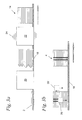
- Fig. 3a, b show in a schematic representation of a device for marking a stack 14 plate-like elements 2, with which the inventive method is feasible.
- a conveying device 18 On a conveying device 18 (the hatched arrow indicates the flow direction) are single, preferably similar, plate-shaped elements 2 continuously one in Fig. 3a supplied stacking device 20 shown.
- the stacking device 20 brings the plate-like elements 2 in planar contact their main surfaces to each other, so that a stack 14 is formed.
- the stack 14 can then one more, also in Fig. 3a shown, adjusting device 22 are fed, which fixes any non-aligned system of the plate-like elements 2 (here heavily oversubscribed).
- the alignment is performed by means of vibrations 24.
- the alignment can also be done in other ways. It is also possible to fix the plate-like elements 2 in the aligned stack 14, so that their position is ensured to each other in the alignment state. However, this is not always necessary.
- the aligned stack 14 can now from an in Fig. 3b shown marking device 26 are provided on a side surface with a mark 4.
- the marking device 26 is during the marking process in the arrow direction transverse to the direction of extension of the narrow surfaces 10 of the individual plate-like elements 2 moves.
- the marking device 26 may, for example, comprise a print head or a laser with which the marking 4 is produced.
- a drying device not shown which dries the ink marking 4 on the side surface in time for application, and thus the risk of smearing or blurring of the mark 4 during further processing reduced.
- a laser is used for marking
- a suction device (not shown) which sucks any gases which may be produced by the action of the laser on the side surface.
- the marking 4 is preferably applied as a bar code transversely to the direction of extension of the narrow surfaces 10 of the individual plate-like elements 2 of the stack 14.
- the time required for the marking process can be reduced.
- the marker 4 is then applied only on a comparatively small portion of the side surface of the stack 14, which facilitates the detection of the marker 4, for example, the opto-electronic, mechanical scanning or ultrasound-based, preferably automated, reading a bar code.
- the marking motifs can be changed flexibly and adapted in a short time to the present application. Furthermore, it may be provided to provide the stack 14 on a further side surface with a mark 4 ', for which optionally a further marking device 26 '(dashed) can be used.
- the stack 14 provided with a marking 4 can now be supplied to its further destination.
- the labeling process may be followed by the packaging of the stack 14.
- the stacking device 20 shown devices 20, 22, 26, 26 'of the embodiment are shown separately. However, this has happened only for the sake of clarity. It is of course possible to combine the stacking device 20, the adjusting device 22 and / or the marking device 26 in a multi-functional device. Then, the above-described steps can be performed substantially simultaneously or at least close to each other, without the conveyor 18, the plate-like elements 2 or the stack 14 moves on.
- Fig. 4 shows a plate-like element 2.
- the plate-like element 2 is provided in this example on a major surface, namely the surface of the front side 6, with a decor 28, which is why it is unsuitable for a mark 4 on the front side 6.
- a mark 4 in this example a bar code, is applied on one of the narrow surfaces 10.
- the thickness d of the plate-like member 2 is less than 5 mm, particularly 2 mm to 3 mm, the plate-like member 2 is provided with a detectable mark 4, for example, information about the manufacturing history of the plate-like member 2 emerge.
- Fig. 4 shows an example of a rectangular plate-like element 2 with two short and two long narrow surfaces 10.
- the present invention also includes plate-like elements 2, which in plan view a circular ( Fig. 5a ) or elliptical shape ( Fig. 5b ) and thus have a continuous narrow surface 10.
- plate-like elements 2 which in plan view a circular ( Fig. 5a ) or elliptical shape ( Fig. 5b ) and thus have a continuous narrow surface 10.
- triangles Fig. 5c
- Fig. 5d squares
- the shape of the plate-like elements 2 is not limited to rectangular configurations and thus not limited to a certain number of narrow surfaces 10.
Landscapes
- Engineering & Computer Science (AREA)
- Life Sciences & Earth Sciences (AREA)
- Physics & Mathematics (AREA)
- Optics & Photonics (AREA)
- Mechanical Engineering (AREA)
- Wood Science & Technology (AREA)
- Forests & Forestry (AREA)
- Laser Beam Processing (AREA)
- Printing Methods (AREA)
- Sealing Battery Cases Or Jackets (AREA)
Applications Claiming Priority (1)
| Application Number | Priority Date | Filing Date | Title |
|---|---|---|---|
| DE102007058029A DE102007058029A1 (de) | 2007-11-30 | 2007-11-30 | Verfahren und Vorrichtung zur Markierung eines Stapels plattenartiger Elemente, mit Markierung versehener Stapel sowie plattenartiges Element |
Publications (2)
| Publication Number | Publication Date |
|---|---|
| EP2065149A1 true EP2065149A1 (fr) | 2009-06-03 |
| EP2065149B1 EP2065149B1 (fr) | 2016-03-23 |
Family
ID=40386474
Family Applications (1)
| Application Number | Title | Priority Date | Filing Date |
|---|---|---|---|
| EP08105709.3A Active EP2065149B1 (fr) | 2007-11-30 | 2008-10-30 | Procédé et dispositif destinés au marquage d'une pile d'éléments de type plaques, pile dotée d'un marquage ainsi qu'élément de type plaque |
Country Status (6)
| Country | Link |
|---|---|
| EP (1) | EP2065149B1 (fr) |
| DE (1) | DE102007058029A1 (fr) |
| ES (1) | ES2576458T3 (fr) |
| HU (1) | HUE029234T2 (fr) |
| PL (1) | PL2065149T3 (fr) |
| PT (1) | PT2065149E (fr) |
Cited By (4)
| Publication number | Priority date | Publication date | Assignee | Title |
|---|---|---|---|---|
| DE102010029261A1 (de) * | 2010-05-25 | 2011-12-01 | Rofin-Baasel Lasertech Gmbh & Co. Kg | Verfahren und Vorrichtung zum Markieren von Möbelbauplatten |
| DE102014208746A1 (de) * | 2014-05-09 | 2015-11-12 | Homag Holzbearbeitungssysteme Gmbh | Verfahren zum Kennzeichnen von Werkstücken |
| US11110732B2 (en) | 2018-03-02 | 2021-09-07 | Signode Canada Ulc | Lumber stack marking machine and methods of applying markings to lumber stacks |
| EP4629136A1 (fr) | 2024-04-05 | 2025-10-08 | Motta, Giuseppina | Procédé d'identification et de traçage de panneaux pour meubles |
Families Citing this family (4)
| Publication number | Priority date | Publication date | Assignee | Title |
|---|---|---|---|---|
| DE102013004332B4 (de) | 2013-03-14 | 2016-05-12 | Fritz Egger Gmbh & Co. Og | Verfahren und Vorrichtung zur Herstellung eines Lignocellulose enthaltenden, plattenförmigen Werkstoffs |
| DE102014222657B4 (de) * | 2014-11-06 | 2018-03-01 | Koenig & Bauer Ag | Verfahren zum Erzeugen oder Verändern zumindest eines Begleitdokuments eines Stapels von Flachmaterial |
| DE102015212409A1 (de) * | 2015-07-02 | 2017-01-05 | Homag Holzbearbeitungssysteme Gmbh | Verfahren zum Beschichten und Kennzeichnen von Werkstücken |
| DE102022128151A1 (de) * | 2022-10-25 | 2024-04-25 | Bayerische Motoren Werke Aktiengesellschaft | Verfahren und Vorrichtung zum Bearbeiten von Halbzeugen |
Citations (5)
| Publication number | Priority date | Publication date | Assignee | Title |
|---|---|---|---|---|
| US1977971A (en) * | 1932-03-17 | 1934-10-23 | Gen Timber Service Inc | Lumber trimming and marking machine |
| US5554427A (en) | 1991-10-15 | 1996-09-10 | Georgia-Pacific Corporation | Sheet material edge labeling |
| US6174036B1 (en) * | 1995-01-06 | 2001-01-16 | James A. Aman | Automated end labeler system |
| WO2002095327A1 (fr) | 2001-05-21 | 2002-11-28 | Metso Panelboard Oy | Procede et appareil permettant de definir la position de la surface laterale d'objets empiles, tels que des planches |
| WO2002094570A1 (fr) * | 2001-05-21 | 2002-11-28 | Metso Panelboard Oy | Procede et appareil servant a marquer des objets tels que des planches, disposes en pile |
Family Cites Families (4)
| Publication number | Priority date | Publication date | Assignee | Title |
|---|---|---|---|---|
| US2833208A (en) * | 1953-12-22 | 1958-05-06 | Western Gear Works | Machine for edge-marking panels |
| JP3083864B2 (ja) * | 1991-04-26 | 2000-09-04 | 旭化成工業株式会社 | 自動マーキング装置 |
| DE19736000A1 (de) * | 1997-08-19 | 1999-02-25 | Heberndorfer Leistenfabrik | Verfahren und Vorrichtung zum Aufbringen von Zeichen auf zum Verkauf bestimmten Erzeugnissen |
| DE102005020977A1 (de) * | 2005-04-29 | 2006-11-02 | Holzma Plattenaufteiltechnik Gmbh | Abstapelungsvorrichtung zum Abstapeln plattenförmiger Werkstücke |
-
2007
- 2007-11-30 DE DE102007058029A patent/DE102007058029A1/de not_active Withdrawn
-
2008
- 2008-10-30 HU HUE08105709A patent/HUE029234T2/en unknown
- 2008-10-30 ES ES08105709.3T patent/ES2576458T3/es active Active
- 2008-10-30 EP EP08105709.3A patent/EP2065149B1/fr active Active
- 2008-10-30 PT PT08105709T patent/PT2065149E/pt unknown
- 2008-10-30 PL PL08105709.3T patent/PL2065149T3/pl unknown
Patent Citations (5)
| Publication number | Priority date | Publication date | Assignee | Title |
|---|---|---|---|---|
| US1977971A (en) * | 1932-03-17 | 1934-10-23 | Gen Timber Service Inc | Lumber trimming and marking machine |
| US5554427A (en) | 1991-10-15 | 1996-09-10 | Georgia-Pacific Corporation | Sheet material edge labeling |
| US6174036B1 (en) * | 1995-01-06 | 2001-01-16 | James A. Aman | Automated end labeler system |
| WO2002095327A1 (fr) | 2001-05-21 | 2002-11-28 | Metso Panelboard Oy | Procede et appareil permettant de definir la position de la surface laterale d'objets empiles, tels que des planches |
| WO2002094570A1 (fr) * | 2001-05-21 | 2002-11-28 | Metso Panelboard Oy | Procede et appareil servant a marquer des objets tels que des planches, disposes en pile |
Cited By (6)
| Publication number | Priority date | Publication date | Assignee | Title |
|---|---|---|---|---|
| DE102010029261A1 (de) * | 2010-05-25 | 2011-12-01 | Rofin-Baasel Lasertech Gmbh & Co. Kg | Verfahren und Vorrichtung zum Markieren von Möbelbauplatten |
| DE102010029261B4 (de) * | 2010-05-25 | 2013-03-28 | Rofin-Baasel Lasertech Gmbh & Co. Kg | Verfahren und Vorrichtung zum Markieren von Möbelbauplatten |
| DE102014208746A1 (de) * | 2014-05-09 | 2015-11-12 | Homag Holzbearbeitungssysteme Gmbh | Verfahren zum Kennzeichnen von Werkstücken |
| EP2942740A3 (fr) * | 2014-05-09 | 2016-03-23 | Homag Holzbearbeitungssysteme GmbH | Procédé de caractérisation de pièces à usiner |
| US11110732B2 (en) | 2018-03-02 | 2021-09-07 | Signode Canada Ulc | Lumber stack marking machine and methods of applying markings to lumber stacks |
| EP4629136A1 (fr) | 2024-04-05 | 2025-10-08 | Motta, Giuseppina | Procédé d'identification et de traçage de panneaux pour meubles |
Also Published As
| Publication number | Publication date |
|---|---|
| PT2065149E (pt) | 2016-06-23 |
| EP2065149B1 (fr) | 2016-03-23 |
| ES2576458T3 (es) | 2016-07-07 |
| DE102007058029A1 (de) | 2009-06-04 |
| PL2065149T3 (pl) | 2016-09-30 |
| HUE029234T2 (en) | 2017-02-28 |
Similar Documents
| Publication | Publication Date | Title |
|---|---|---|
| EP2065149B1 (fr) | Procédé et dispositif destinés au marquage d'une pile d'éléments de type plaques, pile dotée d'un marquage ainsi qu'élément de type plaque | |
| DE102009043812B4 (de) | Verfahren zum Herstellen einer bedruckten Oberfläche auf einem flächigen Werkstück | |
| DE102010010784C5 (de) | Verfahren und Vorrichtung zur Herstellung eines plattenförmigen Produktes mit einer ein Dekor aufweisenden Oberfläche | |
| DE102013004332B4 (de) | Verfahren und Vorrichtung zur Herstellung eines Lignocellulose enthaltenden, plattenförmigen Werkstoffs | |
| WO2008067933A1 (fr) | Procédé et dispositif de production de surfaces individuelles par impression d'au moins un module individuel dérivé d'un modèle d'orgine | |
| EP2461276B1 (fr) | Procédé de traitement de produits sous forme de plaques | |
| WO2014060402A1 (fr) | Procédé de fabrication d'un panneau mural ou de sol décoré | |
| EP2730429A1 (fr) | Procédé de fabrication d'un panneau mural ou de sol décoré | |
| DE102010010785B4 (de) | Verfahren und Vorrichtung zur Herstellung von Dekorpapier zum Beschichten von plattenförmigen Grundkörpern | |
| EP3458279A1 (fr) | Procédé de fabrication d'un profilé de chant et partie de meuble | |
| EP2698249A2 (fr) | Plancher composé de panneaux reliés les uns aux autres et procédé destiné à la pose de panneaux de sol | |
| AT521998B1 (de) | Verfahren zum Bedrucken von länglichen Profilleisten und Profilleisten | |
| DE102008034764A1 (de) | Werkzeug für eine Bogenstanzmaschine | |
| EP3433109B1 (fr) | Procédé de production d'un stratifié | |
| DE102022213489B3 (de) | Herstellung einer dekorativen Oberfläche | |
| EP1798359B1 (fr) | Panneau oblongue avec rainure transversale | |
| AT526342A4 (de) | Vorrichtung und Verfahren zum Bedrucken von Objekten | |
| EP4461550A1 (fr) | Procédé d'application d'un graphique sur un produit fini formé de tiges individuelles en bois | |
| DE2546126C3 (de) | Werkzeug zum Stanzen und/oder Prägen von Papier, Karton, Kunststoff o.dgl | |
| DE102008062598A1 (de) | Verfahren zur Herstellung eines Dekors und Vorrichtung hierfür | |
| DE102015208267A1 (de) | Verfahren und Vorrichtung zum Versehen einer Werkstückfläche mit einem Dekor | |
| DE202013009356U1 (de) | Holzbauelement | |
| DE8302625U1 (de) | Puzzle |
Legal Events
| Date | Code | Title | Description |
|---|---|---|---|
| PUAI | Public reference made under article 153(3) epc to a published international application that has entered the european phase |
Free format text: ORIGINAL CODE: 0009012 |
|
| AK | Designated contracting states |
Kind code of ref document: A1 Designated state(s): AT BE BG CH CY CZ DE DK EE ES FI FR GB GR HR HU IE IS IT LI LT LU LV MC MT NL NO PL PT RO SE SI SK TR |
|
| AX | Request for extension of the european patent |
Extension state: AL BA MK RS |
|
| 17P | Request for examination filed |
Effective date: 20090603 |
|
| 17Q | First examination report despatched |
Effective date: 20090717 |
|
| AKX | Designation fees paid |
Designated state(s): AT BE BG CH CY CZ DE DK EE ES FI FR GB GR HR HU IE IS IT LI LT LU LV MC MT NL NO PL PT RO SE SI SK TR |
|
| RAP1 | Party data changed (applicant data changed or rights of an application transferred) |
Owner name: FRITZ EGGER GMBH & CO. OG |
|
| RAP1 | Party data changed (applicant data changed or rights of an application transferred) |
Owner name: FRITZ EGGER GMBH & CO. OG |
|
| GRAP | Despatch of communication of intention to grant a patent |
Free format text: ORIGINAL CODE: EPIDOSNIGR1 |
|
| RIC1 | Information provided on ipc code assigned before grant |
Ipc: B41M 5/26 20060101ALI20150908BHEP Ipc: B41M 5/00 20060101ALI20150908BHEP Ipc: B41J 3/01 20060101ALI20150908BHEP Ipc: B27M 1/00 20060101AFI20150908BHEP Ipc: B41M 1/40 20060101ALI20150908BHEP Ipc: B41J 3/407 20060101ALI20150908BHEP |
|
| INTG | Intention to grant announced |
Effective date: 20150930 |
|
| GRAS | Grant fee paid |
Free format text: ORIGINAL CODE: EPIDOSNIGR3 |
|
| GRAA | (expected) grant |
Free format text: ORIGINAL CODE: 0009210 |
|
| AK | Designated contracting states |
Kind code of ref document: B1 Designated state(s): AT BE BG CH CY CZ DE DK EE ES FI FR GB GR HR HU IE IS IT LI LT LU LV MC MT NL NO PL PT RO SE SI SK TR |
|
| REG | Reference to a national code |
Ref country code: GB Ref legal event code: FG4D Free format text: NOT ENGLISH |
|
| REG | Reference to a national code |
Ref country code: CH Ref legal event code: EP |
|
| REG | Reference to a national code |
Ref country code: AT Ref legal event code: REF Ref document number: 782667 Country of ref document: AT Kind code of ref document: T Effective date: 20160415 |
|
| REG | Reference to a national code |
Ref country code: IE Ref legal event code: FG4D Free format text: LANGUAGE OF EP DOCUMENT: GERMAN |
|
| REG | Reference to a national code |
Ref country code: DE Ref legal event code: R096 Ref document number: 502008013962 Country of ref document: DE |
|
| REG | Reference to a national code |
Ref country code: RO Ref legal event code: EPE |
|
| REG | Reference to a national code |
Ref country code: CH Ref legal event code: NV Representative=s name: SCHMAUDER AND PARTNER AG PATENT- UND MARKENANW, CH |
|
| REG | Reference to a national code |
Ref country code: PT Ref legal event code: SC4A Free format text: AVAILABILITY OF NATIONAL TRANSLATION Effective date: 20160615 |
|
| REG | Reference to a national code |
Ref country code: SE Ref legal event code: TRGR |
|
| REG | Reference to a national code |
Ref country code: ES Ref legal event code: FG2A Ref document number: 2576458 Country of ref document: ES Kind code of ref document: T3 Effective date: 20160707 |
|
| REG | Reference to a national code |
Ref country code: NL Ref legal event code: MP Effective date: 20160323 |
|
| PG25 | Lapsed in a contracting state [announced via postgrant information from national office to epo] |
Ref country code: GR Free format text: LAPSE BECAUSE OF FAILURE TO SUBMIT A TRANSLATION OF THE DESCRIPTION OR TO PAY THE FEE WITHIN THE PRESCRIBED TIME-LIMIT Effective date: 20160624 Ref country code: NO Free format text: LAPSE BECAUSE OF FAILURE TO SUBMIT A TRANSLATION OF THE DESCRIPTION OR TO PAY THE FEE WITHIN THE PRESCRIBED TIME-LIMIT Effective date: 20160623 Ref country code: FI Free format text: LAPSE BECAUSE OF FAILURE TO SUBMIT A TRANSLATION OF THE DESCRIPTION OR TO PAY THE FEE WITHIN THE PRESCRIBED TIME-LIMIT Effective date: 20160323 |
|
| PG25 | Lapsed in a contracting state [announced via postgrant information from national office to epo] |
Ref country code: LV Free format text: LAPSE BECAUSE OF FAILURE TO SUBMIT A TRANSLATION OF THE DESCRIPTION OR TO PAY THE FEE WITHIN THE PRESCRIBED TIME-LIMIT Effective date: 20160323 Ref country code: NL Free format text: LAPSE BECAUSE OF FAILURE TO SUBMIT A TRANSLATION OF THE DESCRIPTION OR TO PAY THE FEE WITHIN THE PRESCRIBED TIME-LIMIT Effective date: 20160323 |
|
| REG | Reference to a national code |
Ref country code: FR Ref legal event code: PLFP Year of fee payment: 9 |
|
| PG25 | Lapsed in a contracting state [announced via postgrant information from national office to epo] |
Ref country code: EE Free format text: LAPSE BECAUSE OF FAILURE TO SUBMIT A TRANSLATION OF THE DESCRIPTION OR TO PAY THE FEE WITHIN THE PRESCRIBED TIME-LIMIT Effective date: 20160323 Ref country code: IS Free format text: LAPSE BECAUSE OF FAILURE TO SUBMIT A TRANSLATION OF THE DESCRIPTION OR TO PAY THE FEE WITHIN THE PRESCRIBED TIME-LIMIT Effective date: 20160723 |
|
| REG | Reference to a national code |
Ref country code: SK Ref legal event code: T3 Ref document number: E 21271 Country of ref document: SK |
|
| REG | Reference to a national code |
Ref country code: DE Ref legal event code: R097 Ref document number: 502008013962 Country of ref document: DE |
|
| PLBE | No opposition filed within time limit |
Free format text: ORIGINAL CODE: 0009261 |
|
| STAA | Information on the status of an ep patent application or granted ep patent |
Free format text: STATUS: NO OPPOSITION FILED WITHIN TIME LIMIT |
|
| PG25 | Lapsed in a contracting state [announced via postgrant information from national office to epo] |
Ref country code: DK Free format text: LAPSE BECAUSE OF FAILURE TO SUBMIT A TRANSLATION OF THE DESCRIPTION OR TO PAY THE FEE WITHIN THE PRESCRIBED TIME-LIMIT Effective date: 20160323 |
|
| PG25 | Lapsed in a contracting state [announced via postgrant information from national office to epo] |
Ref country code: BG Free format text: LAPSE BECAUSE OF FAILURE TO SUBMIT A TRANSLATION OF THE DESCRIPTION OR TO PAY THE FEE WITHIN THE PRESCRIBED TIME-LIMIT Effective date: 20160623 |
|
| REG | Reference to a national code |
Ref country code: HU Ref legal event code: AG4A Ref document number: E029234 Country of ref document: HU |
|
| 26N | No opposition filed |
Effective date: 20170102 |
|
| PG25 | Lapsed in a contracting state [announced via postgrant information from national office to epo] |
Ref country code: SI Free format text: LAPSE BECAUSE OF FAILURE TO SUBMIT A TRANSLATION OF THE DESCRIPTION OR TO PAY THE FEE WITHIN THE PRESCRIBED TIME-LIMIT Effective date: 20160323 |
|
| REG | Reference to a national code |
Ref country code: IE Ref legal event code: MM4A |
|
| REG | Reference to a national code |
Ref country code: FR Ref legal event code: PLFP Year of fee payment: 10 |
|
| PG25 | Lapsed in a contracting state [announced via postgrant information from national office to epo] |
Ref country code: IE Free format text: LAPSE BECAUSE OF NON-PAYMENT OF DUE FEES Effective date: 20161030 |
|
| PG25 | Lapsed in a contracting state [announced via postgrant information from national office to epo] |
Ref country code: CY Free format text: LAPSE BECAUSE OF FAILURE TO SUBMIT A TRANSLATION OF THE DESCRIPTION OR TO PAY THE FEE WITHIN THE PRESCRIBED TIME-LIMIT Effective date: 20160323 |
|
| PG25 | Lapsed in a contracting state [announced via postgrant information from national office to epo] |
Ref country code: MT Free format text: LAPSE BECAUSE OF FAILURE TO SUBMIT A TRANSLATION OF THE DESCRIPTION OR TO PAY THE FEE WITHIN THE PRESCRIBED TIME-LIMIT Effective date: 20160323 Ref country code: HR Free format text: LAPSE BECAUSE OF FAILURE TO SUBMIT A TRANSLATION OF THE DESCRIPTION OR TO PAY THE FEE WITHIN THE PRESCRIBED TIME-LIMIT Effective date: 20160323 Ref country code: MC Free format text: LAPSE BECAUSE OF FAILURE TO SUBMIT A TRANSLATION OF THE DESCRIPTION OR TO PAY THE FEE WITHIN THE PRESCRIBED TIME-LIMIT Effective date: 20160323 |
|
| REG | Reference to a national code |
Ref country code: FR Ref legal event code: PLFP Year of fee payment: 11 |
|
| PGFP | Annual fee paid to national office [announced via postgrant information from national office to epo] |
Ref country code: TR Payment date: 20220920 Year of fee payment: 15 Ref country code: SK Payment date: 20220922 Year of fee payment: 15 Ref country code: PT Payment date: 20220922 Year of fee payment: 15 Ref country code: LT Payment date: 20220919 Year of fee payment: 15 Ref country code: CZ Payment date: 20220922 Year of fee payment: 15 |
|
| PGFP | Annual fee paid to national office [announced via postgrant information from national office to epo] |
Ref country code: FR Payment date: 20221025 Year of fee payment: 15 |
|
| PGFP | Annual fee paid to national office [announced via postgrant information from national office to epo] |
Ref country code: SE Payment date: 20221024 Year of fee payment: 15 Ref country code: RO Payment date: 20221004 Year of fee payment: 15 Ref country code: LU Payment date: 20221024 Year of fee payment: 15 Ref country code: IT Payment date: 20221026 Year of fee payment: 15 Ref country code: GB Payment date: 20221024 Year of fee payment: 15 Ref country code: ES Payment date: 20221124 Year of fee payment: 15 Ref country code: DE Payment date: 20221024 Year of fee payment: 15 Ref country code: AT Payment date: 20221025 Year of fee payment: 15 |
|
| PGFP | Annual fee paid to national office [announced via postgrant information from national office to epo] |
Ref country code: PL Payment date: 20221021 Year of fee payment: 15 Ref country code: HU Payment date: 20220924 Year of fee payment: 15 Ref country code: CH Payment date: 20221026 Year of fee payment: 15 Ref country code: BE Payment date: 20221024 Year of fee payment: 15 |
|
| REG | Reference to a national code |
Ref country code: DE Ref legal event code: R119 Ref document number: 502008013962 Country of ref document: DE |
|
| REG | Reference to a national code |
Ref country code: LT Ref legal event code: MM4D Effective date: 20231030 |
|
| REG | Reference to a national code |
Ref country code: SE Ref legal event code: EUG |
|
| REG | Reference to a national code |
Ref country code: CH Ref legal event code: PL |
|
| REG | Reference to a national code |
Ref country code: AT Ref legal event code: MM01 Ref document number: 782667 Country of ref document: AT Kind code of ref document: T Effective date: 20231030 |
|
| REG | Reference to a national code |
Ref country code: BE Ref legal event code: MM Effective date: 20231031 |
|
| PG25 | Lapsed in a contracting state [announced via postgrant information from national office to epo] |
Ref country code: LU Free format text: LAPSE BECAUSE OF NON-PAYMENT OF DUE FEES Effective date: 20231030 |
|
| REG | Reference to a national code |
Ref country code: SK Ref legal event code: MM4A Ref document number: E 21271 Country of ref document: SK Effective date: 20231030 |
|
| GBPC | Gb: european patent ceased through non-payment of renewal fee |
Effective date: 20231030 |
|
| PG25 | Lapsed in a contracting state [announced via postgrant information from national office to epo] |
Ref country code: LU Free format text: LAPSE BECAUSE OF NON-PAYMENT OF DUE FEES Effective date: 20231030 |
|
| PG25 | Lapsed in a contracting state [announced via postgrant information from national office to epo] |
Ref country code: GB Free format text: LAPSE BECAUSE OF NON-PAYMENT OF DUE FEES Effective date: 20231030 |
|
| PG25 | Lapsed in a contracting state [announced via postgrant information from national office to epo] |
Ref country code: LT Free format text: LAPSE BECAUSE OF NON-PAYMENT OF DUE FEES Effective date: 20231030 |
|
| PG25 | Lapsed in a contracting state [announced via postgrant information from national office to epo] |
Ref country code: CH Free format text: LAPSE BECAUSE OF NON-PAYMENT OF DUE FEES Effective date: 20231031 |
|
| PG25 | Lapsed in a contracting state [announced via postgrant information from national office to epo] |
Ref country code: AT Free format text: LAPSE BECAUSE OF NON-PAYMENT OF DUE FEES Effective date: 20231030 Ref country code: CZ Free format text: LAPSE BECAUSE OF NON-PAYMENT OF DUE FEES Effective date: 20231030 |
|
| PG25 | Lapsed in a contracting state [announced via postgrant information from national office to epo] |
Ref country code: SK Free format text: LAPSE BECAUSE OF NON-PAYMENT OF DUE FEES Effective date: 20231030 |
|
| PG25 | Lapsed in a contracting state [announced via postgrant information from national office to epo] |
Ref country code: SK Free format text: LAPSE BECAUSE OF NON-PAYMENT OF DUE FEES Effective date: 20231030 Ref country code: RO Free format text: LAPSE BECAUSE OF NON-PAYMENT OF DUE FEES Effective date: 20231030 Ref country code: LT Free format text: LAPSE BECAUSE OF NON-PAYMENT OF DUE FEES Effective date: 20231030 Ref country code: GB Free format text: LAPSE BECAUSE OF NON-PAYMENT OF DUE FEES Effective date: 20231030 Ref country code: FR Free format text: LAPSE BECAUSE OF NON-PAYMENT OF DUE FEES Effective date: 20231031 Ref country code: DE Free format text: LAPSE BECAUSE OF NON-PAYMENT OF DUE FEES Effective date: 20240501 Ref country code: CZ Free format text: LAPSE BECAUSE OF NON-PAYMENT OF DUE FEES Effective date: 20231030 Ref country code: CH Free format text: LAPSE BECAUSE OF NON-PAYMENT OF DUE FEES Effective date: 20231031 Ref country code: AT Free format text: LAPSE BECAUSE OF NON-PAYMENT OF DUE FEES Effective date: 20231030 |
|
| PG25 | Lapsed in a contracting state [announced via postgrant information from national office to epo] |
Ref country code: PT Free format text: LAPSE BECAUSE OF NON-PAYMENT OF DUE FEES Effective date: 20240430 |
|
| PG25 | Lapsed in a contracting state [announced via postgrant information from national office to epo] |
Ref country code: SE Free format text: LAPSE BECAUSE OF NON-PAYMENT OF DUE FEES Effective date: 20231031 Ref country code: PT Free format text: LAPSE BECAUSE OF NON-PAYMENT OF DUE FEES Effective date: 20240430 Ref country code: HU Free format text: LAPSE BECAUSE OF NON-PAYMENT OF DUE FEES Effective date: 20231031 Ref country code: BE Free format text: LAPSE BECAUSE OF NON-PAYMENT OF DUE FEES Effective date: 20231031 |
|
| PG25 | Lapsed in a contracting state [announced via postgrant information from national office to epo] |
Ref country code: IT Free format text: LAPSE BECAUSE OF NON-PAYMENT OF DUE FEES Effective date: 20231030 |
|
| REG | Reference to a national code |
Ref country code: ES Ref legal event code: FD2A Effective date: 20241216 |
|
| PG25 | Lapsed in a contracting state [announced via postgrant information from national office to epo] |
Ref country code: IT Free format text: LAPSE BECAUSE OF NON-PAYMENT OF DUE FEES Effective date: 20231030 |
|
| PG25 | Lapsed in a contracting state [announced via postgrant information from national office to epo] |
Ref country code: ES Free format text: LAPSE BECAUSE OF NON-PAYMENT OF DUE FEES Effective date: 20231031 |
|
| PG25 | Lapsed in a contracting state [announced via postgrant information from national office to epo] |
Ref country code: ES Free format text: LAPSE BECAUSE OF NON-PAYMENT OF DUE FEES Effective date: 20231031 |
|
| PG25 | Lapsed in a contracting state [announced via postgrant information from national office to epo] |
Ref country code: PL Free format text: LAPSE BECAUSE OF NON-PAYMENT OF DUE FEES Effective date: 20231030 |