EP2065190A2 - Verfahren zum Betreiben eines Druckwerks einer Druckmaschine - Google Patents
Verfahren zum Betreiben eines Druckwerks einer Druckmaschine Download PDFInfo
- Publication number
- EP2065190A2 EP2065190A2 EP08105455A EP08105455A EP2065190A2 EP 2065190 A2 EP2065190 A2 EP 2065190A2 EP 08105455 A EP08105455 A EP 08105455A EP 08105455 A EP08105455 A EP 08105455A EP 2065190 A2 EP2065190 A2 EP 2065190A2
- Authority
- EP
- European Patent Office
- Prior art keywords
- motor
- printing
- operating mode
- gear
- cylinder
- Prior art date
- Legal status (The legal status is an assumption and is not a legal conclusion. Google has not performed a legal analysis and makes no representation as to the accuracy of the status listed.)
- Granted
Links
Images
Classifications
-
- B—PERFORMING OPERATIONS; TRANSPORTING
- B41—PRINTING; LINING MACHINES; TYPEWRITERS; STAMPS
- B41F—PRINTING MACHINES OR PRESSES
- B41F13/00—Common details of rotary presses or machines
- B41F13/008—Mechanical features of drives, e.g. gears, clutches
-
- B—PERFORMING OPERATIONS; TRANSPORTING
- B41—PRINTING; LINING MACHINES; TYPEWRITERS; STAMPS
- B41F—PRINTING MACHINES OR PRESSES
- B41F13/00—Common details of rotary presses or machines
- B41F13/004—Electric or hydraulic features of drives
- B41F13/0045—Electric driving devices
-
- B—PERFORMING OPERATIONS; TRANSPORTING
- B41—PRINTING; LINING MACHINES; TYPEWRITERS; STAMPS
- B41F—PRINTING MACHINES OR PRESSES
- B41F31/00—Inking arrangements or devices
- B41F31/004—Driving means for ink rollers
-
- B—PERFORMING OPERATIONS; TRANSPORTING
- B41—PRINTING; LINING MACHINES; TYPEWRITERS; STAMPS
- B41P—INDEXING SCHEME RELATING TO PRINTING, LINING MACHINES, TYPEWRITERS, AND TO STAMPS
- B41P2213/00—Arrangements for actuating or driving printing presses; Auxiliary devices or processes
- B41P2213/10—Constitutive elements of driving devices
- B41P2213/25—Couplings; Clutches
Definitions
- the present invention relates to a method for operating a printing unit of a printing machine, wherein in a first mode of operation by a first motor, a printing cylinder and a friction roller are rotatably driven and by a second motor, the friction roller is axially driven, and wherein in a second mode of operation by the second Motor, the friction roller is driven axially, and a suitable for performing this method printing machine.
- the invention is therefore based on the object to provide a cost-effective for realizing method for operating a printing unit of a printing press and to create a suitable for carrying out this method printing machine.
- the inventive method for operating a printing unit of a printing press wherein in a first operating mode by a first motor, the rotation of a printing cylinder and the rotation of a friction roller are driven and in the In the first mode of operation by a second motor, the axial movement of the friction roller is driven, and wherein in a second mode of operation by the second motor, the axial movement of the friction roller is driven, characterized in that in the second mode of operation by a third motor, the rotation of the friction roller is driven.
- the printing press according to the invention comprises a printing unit with a printing cylinder, a friction roller, a first motor for rotationally driving both the printing couple cylinder and the friction roller in a first operating mode and with a second motor for both in the first operating mode and in the second operating mode axial driving of the friction roller, wherein the printing machine according to the invention is characterized in that a third motor for taking place in the second operating mode rotationally driving the friction roller is present.
- An advantage of the invention is the fact that is replaced by the third motor present at the beginning of the prior art second clutch. It has been found that commercially available electric motors which can be used as the third motor are less expensive than the clutch on the market.
- a clutch is interposed between the first motor and the friction roller, which is kept closed in the first operating mode and is kept open in the second operating mode.
- This coupling may be the only coupling available to rotatably drive the inking unit of the printing unit.
- Another intended for this purpose clutch which is present in the described prior art, is not required.
- the third motor in the first operating mode, is rotationally driven by the first motor.
- the third motor runs in the so-called generator mode without current.
- the third motor in the first operating mode, is supplied with current in such a way that the third motor brakes the first motor.
- a tension of gears can be achieved against each other, which are arranged between the first motor and the third motor.
- the third motor compensates for or at least minimizes torsional vibrations caused by the first motor or the toothed gearing.
- the first operating mode is the printing operation and the second operating mode is a maintenance operation.
- This maintenance operation may be, for example, a cleaning operation for washing the inking unit.
- the printing unit cylinder is rotationally driven in the second operating mode by the first motor. This can be provided in the event that the inking unit and the printing cylinder are to be cleaned simultaneously in the second operating mode. Instead, however, it may also be provided that in the second operating mode the first motor and the printing cylinder rest while only the inking unit driven in rotation by the third motor is cleaned.
- the printing cylinder is either a counter-pressure cylinder or a plate cylinder.
- a counter-pressure cylinder of the printing unit and a printing forme cylinder of the printing unit are connected via a gear transmission with each other and with the first motor, that in both operating modes or at least in the first operating mode, both the impression cylinder and the plate cylinder by the first motor be driven rotatively.
- the first motor may be a so-called main drive of the printing press, which drives all the printing units in the manner described above.
- This main drive of the printing press can be connected in parallel with another main drive of the printing press, so that in the two operating modes or at least in the first operating mode by a plurality of parallel main drives the printing cylinder, ie counter-pressure cylinder and plate cylinder and, if appropriate, blanket cylinder, the printing units are driven rotatively.
- the counter-pressure cylinders of the printing units are driven by the single main drive or parallel main drives and the printing forme cylinder of the respective printing unit is assigned a separate drive, which forms the first motor, in the first operating mode, the plate cylinder and the Rubbing roller rotatably drives and in the second mode of operation, the printing forme cylinder, but not the friction roller rotatably drives.
- the printing machine according to the invention is preferably a sheet-fed printing press in which sheet-shaped printing material is printed in the first operating mode.
- the printing press is a sheet-fed rotary printing machine for lithographic offset printing.
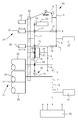
- the single FIGURE shows a detail of a printing machine 26.
- the detail shows a printing unit 27 for printing on sheets 37.
- the printing unit 27 includes a printing cylinder as a printing plate cylinder 28, a blanket cylinder 29 and a counter-pressure cylinder 30. Furthermore, the printing unit 27 includes an inking unit 34 for coloring the Printing forme cylinder 28 and a dampening 35. Drawn illustrated is a transmission element of the dampening unit 35, but are not the dampening rollers.
- the inking unit 34 includes a squeegee roller 33, a first rubbing roller 31 and a second rubbing roller 32.
- an ink fountain roller with an ink fountain further rubbing rollers, transfer rollers and inking rollers are also components of the inking unit 34, but not shown for reasons of clarity clarity.
- the squeegee roller 33 oscillates between the aforementioned ink fountain roller and the first friction roller 31 back and forth, so that the squeegee roller 33 alternately with the Ink fountain roller and the first rubbing roller 31 comes into contact to transfer from the former to the latter, the ink.
- the lifting roller 31 is mounted in a lever which is shown only symbolically in the drawing. The oscillating movement of this lever is driven by a cam gear, which includes a radial cam 18 and a lever attached to the control cam 18 and running cam follower.
- a first motor 21 is connected to a first gear 1, which is drivingly connected via an intermediate gear 16 with a second gear 2.
- the first motor 21 is an electric motor and is the main drive of the printing machine 26.
- On a shaft which rotatably connects the third gear 3 with the plate cylinder 28 is seated non-rotatably a fourth gear 4, which meshes with a fifth gear 5.
- a second motor 22 is connected to a sixth gear 6, which meshes with a seventh gear 7 and an eighth gear 8, d. H. is in mutual meshing.
- the second motor 22 is an electric motor and is an auxiliary drive which serves to drive the axial traversing movement of the friction rollers and to drive the swinging movement of the lifter roller 33.
- the seventh gear 7 is drivingly connected via a traverse gear 19 with the second friction roller 32.
- the eighth gear 8 is connected via a similar traversing gear 19 with the first friction roller 31.
- the traversing gear 19 convert the rotational movements of the gears 7, 8 in axial traversing movements of the friction rollers 31, 33 and are indicated only symbolically in the drawing.
- the eighth gear 8 meshes with a ninth gear 9, which is arranged coaxially with the control cam 18 and rotatably connected.
- a ninth gear 9 which is arranged coaxially with the control cam 18 and rotatably connected.
- the consisting of the gears 6, 8, 9 gear train drives the second motor 22, the rotation of the control cam 18 and thus the oscillating lifting movement of the lifter roller 33rd
- a third motor 23 is connected to a tenth gear 10, which via a symbolically indicated in the drawing intermediate gear 17 with an eleventh gear 11th drive technology is connected.
- the third motor 23 is an electric motor and serves to drive the rotation of the friction rollers 31, 32 and a friction roller of the dampening unit 35, not shown in the drawing.
- the intermediate gear 17 is, like the intermediate gear 16, a gear train.
- To the intermediate gear 17 includes a gear which is arranged coaxially with the first friction roller 31 and rotatably connected.
- the eleventh gear 11 meshes with a twelfth gear 12, which is arranged coaxially with the second friction roller 32 and rotatably connected.
- the twelfth gear 12 is firmly seated on the shaft of the second friction roller 32 and meshes with a thirteenth gear 13, which in turn meshes with a fourteenth gear 14.
- the fourteenth gear 14 is coaxially disposed with the printing form cylinder 28 and rotatably supported by a pivot bearing 24 on that shaft on which the third gear 3 and the fourth gear 4 are fixed.
- the fourteenth gear 14 meshes with a fifteenth gear 15, which is part of a transmission of the dampening unit 35.
- the thirteenth gear 13 is rotatably supported by a pivot bearing 38 on a shaft 39 on which the fifth gear 5 is firmly seated.
- the thirteenth gear 13 can be connected in rotation with the shaft 39 and thus with the fifth gear 5 if necessary.
- the thirteenth gear 13 In the closed switching state of the clutch 20, the thirteenth gear 13 is rotatably connected to the shaft 39 and the fifth gear 5 and in the released switching state of the clutch 20, the thirteenth gear 13 with the shaft 39 and the fifth gear 5 is not rotatably connected.
- the thirteenth gear 13 In the opened switching state of the clutch 20, the thirteenth gear 13 can rotate freely on the shaft 39.
- the above-described cylinders, rollers and gears or their shafts are rotatably mounted in a side wall 25 of a machine frame.
- the printing machine 26 includes an electronic control device 36, which controls the motors 21, 22, 23 and the clutch 20 in accordance with the operating modes explained below.
- the printing machine 26 is operated as follows:
- a first operating mode - the printing operation - drives the first motor 21 via the gears 1, 2, 3, the rotations of the plate cylinder 28 and the blanket cylinder 29 on.
- the first motor 21 also drives via a gear of the intermediate gear 16, the rotation of the impression cylinder 30 at.
- the clutch 20 In the first operating mode, the clutch 20 is closed, so that the clutch 20 transmits the drive power of the first motor 21 from the fifth gear 5 to the thirteenth gear 13.
- the driving power of the first motor 21 is transmitted from the thirteenth gear 13 to the twelfth gear 12, which is coaxially arranged with the second friction roller 32 and rotatably connected.
- the drive power is transmitted via the eleventh gear 11 to the already mentioned gear, which is arranged coaxially with the first friction roller 31 and rotatably connected.
- This latter gear is part of the intermediate gear 17 and sits firmly on the shaft of the first friction roller 31. From the intermediate gear 17, the driving power of the first motor 21 is transmitted via the tenth gear 10 to the third motor 23.
- the third motor 23 may be controlled by the control device 36 such that the supply of electric current to the third motor 23 is inhibited and the latter rotates in the de-energized passive idle with the tenth gear 10.
- the third motor 23 is supplied with electric current in the first operating mode such that in this variant as in the above-explained passive-idling variant, the first motor 21 dominates or rotatively drives the third motor 23 in the first operating mode.
- the second motor 22 drives the axial reciprocation of the friction rollers 31, 32 via the gears 6, 7, 8 and the traversing gears 19.
- the control device 36 regulates the rotational speed of the second motor 22 in such a way that the friction rollers 31, 32 execute a full axial oscillation in each case within two full revolutions of the plate cylinder 28.
- the operating personnel can steplessly adjust the so-called time of use of the friction rollers 31, 32 on the control device 36. In this adjustment, the rotational angle position of the second motor 22 is changed relative to the rotational angular position of the first motor 21, so that the phase position of the dead center of the axial vibration of the friction rollers 31, 32 relative to Rotation angle position of the plate cylinder 28 is changed.
- the lifting movement of the lifter roller 33 is also driven by the second motor 22, wherein the lifter roller 33 performs a full oscillation within each of three full revolutions of the plate cylinder 28.
- the lifter roller 33 is thus 1/3 tour, while the friction rollers 31, 32 are 1/2 tour.
- a second operating mode the maintenance operation - the inking unit 34 and the dampening unit 35 are washed by a cleaning device of the printing unit 27, not shown in the drawing.
- the axial traversing motion of the friction rollers 31, 32 is driven by the second motor 22 in the same manner as in the first mode of operation.
- the clutch 20 is opened, so that the thirteenth gear 13 is no longer rotatably connected to the shaft 39 and the fifth gear 5. With the clutch 20 disengaged, the thirteenth gear 13 is rotatable about the shaft 39 and relative to the fifth gear.
- no drive power and rotational movement can be transmitted from the first motor 21 to the friction rollers 31, 32 and the third motor 23.
- the rotation of the friction rollers 31, 32 is driven by the third motor 23, wherein the driving power of the third motor 23 via the tenth gear 10 and the intermediate gear 17 is transmitted to the shaft of the first friction roller 31 and from the intermediate gear 17 via the eleventh gear 11 and the twelfth gear 12 is transmitted to the shaft of the second friction roller 32.
- the first motor 21 may be stopped or may be driven by the first motor 21 to drive the rotational movement of the printing cylinder 28, 29, 30 or one of these cylinders.
- the ratio of the rotational speed of the friction rollers 31, 32 relative to the rotational speed of the printing cylinder 28 to 39 may be different than in the first operating mode.
Landscapes
- Engineering & Computer Science (AREA)
- Mechanical Engineering (AREA)
- Inking, Control Or Cleaning Of Printing Machines (AREA)
- Rotary Presses (AREA)
Abstract
Description
- Die vorliegende Erfindung betrifft ein Verfahren zum Betreiben eines Druckwerks einer Druckmaschine, wobei in einem ersten Betriebsmodus durch einen ersten Motor ein Druckwerkszylinder und eine Reibwalze rotativ angetrieben werden und durch einen zweiten Motor die Reibwalze axial angetrieben wird, und wobei in einem zweiten Betriebsmodus durch den zweiten Motor die Reibwalze axial angetrieben wird, und eine zur Durchführung dieses Verfahrens geeignete Druckmaschine.
- In
EP 1 167 026 B1 ist eine Druckmaschine beschrieben, bei welcher in einem ersten Betriebsmodus durch einen ersten Motor ein Druckwerkszylinder und eine Reibwalze rotativ angetrieben werden und durch einen zweiten Motor die Reibwalze axial angetrieben wird, und bei der in einem zweiten Betriebsmodus durch den ersten Motor der Druckwerkszylinder rotativ angetrieben wird und durch den zweiten Motor die Reibwalze axial angetrieben wird. Bei dieser Druckmaschine des Standes der Technik wird im zweiten Betriebsmodus durch den zweiten Motor die Reibwalze rotativ angetrieben. Zur Realisierung der beiden Betriebsmodi sind zwei schaltbare Kupplungen erforderlich, welche vergleichsweise teuer sind. - Deshalb liegt der Erfindung die Aufgabe zugrunde, ein kostengünstiger zur realisierendes Verfahren zum Betreiben eines Druckwerks einer Druckmaschine anzugeben und eine zur Durchführung dieses Verfahrens geeignete Druckmaschine zu schaffen.
- Diese Aufgabe wird durch ein Verfahren mit den Merkmalen des Anspruchs 1 und durch eine Druckmaschine mit den Merkmalen des Anspruchs 11 gelöst.
- Das erfindungsgemäße Verfahren zum Betreiben eines Druckwerks einer Druckmaschine, wobei in einem ersten Betriebsmodus durch einen ersten Motor die Rotation eines Druckwerkszylinders und die Rotation einer Reibwalze angetrieben werden und in dem ersten Betriebsmodus durch einen zweiten Motor die Axialbewegung der Reibwalze angetrieben wird, und wobei in einem zweiten Betriebsmodus durch den zweiten Motor die Axialbewegung der Reibwalze angetrieben wird, ist dadurch gekennzeichnet, dass in dem zweiten Betriebsmodus durch einen dritten Motor die Rotation der Reibwalze angetrieben wird.
- Demgemäß umfasst die erfindungsgemäße Druckmaschine ein Druckwerk mit einem Druckwerkszylinder, einer Reibwalze, einem ersten Motor zum in einem ersten Betriebsmodus erfolgenden rotativen Antreiben sowohl des Druckwerkszylinders als auch der Reibwalze und mit einem zweiten Motor zum sowohl in dem ersten Betriebsmodus als auch in dem zweiten Betriebsmodus erfolgenden axialen Antreiben der Reibwalze, wobei die erfindungsgemäße Druckmaschine dadurch gekennzeichnet ist, dass ein dritter Motor zum in dem zweiten Betriebsmodus erfolgenden rotativen Antreiben der Reibwalze vorhanden ist.
- Ein Vorteil der Erfindung ist darin zu sehen, dass durch den dritten Motor die beim eingangs beschriebenen Stand der Technik vorhandene zweite Kupplung ersetzt ist. Es hat sich herausgestellt, dass auf dem Markt erhältliche Elektromotoren, die als der dritte Motor verwendet werden können, kostengünstiger als auf dem Markt befindliche Schaltkupplungen sind.
- Es sind verschiedene Weiterbildungen der Erfindung möglich, die nachfolgend kurz erläutert werden. Bei einer Weiterbildung ist dem ersten Motor und der Reibwalze eine Kupplung zwischengeschaltet, die in dem ersten Betriebsmodus geschlossen gehalten wird und in dem zweiten Betriebsmodus geöffnet gehalten wird. Diese Kupplung kann die einzige für das rotative Antreiben des Farbwerks des Druckwerks vorhandene Kupplung sein. Eine weitere für diesen Zweck vorgesehene Kupplung, die beim beschriebenen Stand der Technik vorhanden ist, ist nicht erforderlich.
- Bei einer weiteren Weiterbildung wird in dem ersten Betriebsmodus der dritte Motor durch den ersten Motor rotativ angetrieben. Hierbei kann es vorgesehen sein, dass in dem ersten Betriebsmodus der dritte Motor im sogenannten Generatorbetrieb stromlos mitläuft. Es kann stattdessen auch vorgesehen sein, dass in dem ersten Betriebsmodus der dritte Motor derart Strom versorgt ist, dass der dritte Motor den ersten Motor bremst. Durch beide Varianten lässt sich eine Verspannung von Zahnrädern gegeneinander erreichen, die zwischen dem ersten Motor und dem dritten Motor angeordnet sind. Durch diese Verspannung der Zahnräder wird deren Zahnflankenkontakt gesichert, was hinsichtlich einer hohen Druckqualität vorteilhaft ist. Ebenso ist es möglich, den dritten Motor derart anzusteuern, dass in dem ersten Betriebsmodus der dritte Motor von dem ersten Motor oder dem Zahnradgetriebe verursachte Drehschwingungen kompensiert oder zumindest minimiert.
- Bei einer weiteren Weiterbildung ist der erste Betriebsmodus der Druckbetrieb und ist der zweite Betriebsmodus ein Wartungsbetrieb. Dieser Wartungsbetrieb kann beispielsweise ein Reinigungsbetrieb zum Waschen des Farbwerks sein.
- Bei einer weiteren Weiterbildung wird in dem zweiten Betriebsmodus durch den ersten Motor der Druckwerkszylinder rotativ angetrieben. Dies kann für den Fall vorgesehen sein, dass in dem zweiten Betriebsmodus das Farbwerk und der Druckwerkszylinder gleichzeitig gereinigt werden sollen. Stattdessen kann es aber auch vorgesehen sein, dass in dem zweiten Betriebsmodus der erste Motor und der Druckwerkszylinder stillstehen während nur das vom dritten Motor rotativ angetriebene Farbwerk gereinigt wird.
- Bei weiteren Weiterbildungen ist der Druckwerkszylinder entweder ein Gegendruckzylinder oder ein Druckformzylinder. Ebenso kann es vorgesehen sein, dass ein Gegendruckzylinder des Druckwerks und ein Druckformzylinder des Druckwerks über ein Zahnradgetriebe derart miteinander und mit dem ersten Motor verbunden sind, dass in beiden Betriebsmodi oder zumindest in dem ersten Betriebsmodus sowohl der Gegendruckzylinder als auch der Druckformzylinder durch den ersten Motor rotativ angetrieben werden. Wenn die Druckmaschine mehrere in der zuvor beschriebenen Weise ausgebildete Druckwerke umfasst, kann der erste Motor ein sogenannter Hauptantrieb der Druckmaschine sein, welcher sämtliche Druckwerke in der zuvor beschriebenen Weise antreibt. Dieser Hauptantrieb der Druckmaschine kann mit einem weiteren Hauptantrieb der Druckmaschine parallelgeschaltet sein, so dass in den beiden Betriebsmodi oder zumindest in dem ersten Betriebsmodus durch mehrere parallelgeschaltete Hauptantriebe die Druckwerkszylinder, d. h. Gegendruckzylinder und Druckformzylinder und gegebenenfalls Gummituchzylinder, der Druckwerke rotativ angetrieben werden. Es ist auch jene Variante möglich, bei welcher die Gegendruckzylinder der Druckwerke durch den einzigen Hauptantrieb oder die parallelgeschalteten Hauptantriebe rotativ angetrieben werden und dem Druckformzylinder des jeweiligen Druckwerks ein Separatantrieb zugeordnet ist, der den ersten Motor bildet, der in dem ersten Betriebsmodus den Druckformzylinder und die Reibwalze rotativ antreibt und in dem zweiten Betriebsmodus den Druckformzylinder, nicht aber die Reibwalze, rotativ antreibt.
- Die erfindungsgemäße Druckmaschine ist vorzugsweise eine Bogendruckmaschine, in welcher in dem ersten Betriebsmodus bogenförmiger Bedruckstoff bedruckt wird. Vorzugsweise handelt es sich bei der Druckmaschine um eine Bogenrotationsdruckmaschine für den lithographischen Offsetdruck.
- Weitere konstruktive und funktionell vorteilhafte Weiterbildungen der Erfindung ergeben sich aus der nachfolgenden Beschreibung eines bevorzugten Ausführungsbeispiels und der dazugehörigen Zeichnung.
- Deren einzige Figur zeigt ausschnittsweise eine Druckmaschine 26. Der Ausschnitt zeigt ein Druckwerk 27 zum Bedrucken von Bogen 37. Das Druckwerk 27 umfasst als Druckwerkszylinder einen Druckformzylinder 28, einen Gummituchzylinder 29 und einen Gegendruckzylinder 30. Desweiteren umfasst das Druckwerk 27 ein Farbwerk 34 zum Einfärben des Druckformzylinders 28 und ein Feuchtwerk 35. Zeichnerisch dargestellt ist ein Getriebeelement des Feuchtwerks 35, sind jedoch nicht dessen Feuchtwerkswalzen.
- Das Farbwerk 34 umfasst eine Heberwalze 33, eine erste Reibwalze 31 und eine zweite Reibwalze 32. Eine Farbkastenwalze mit einem Farbkasten, weitere Reibwalzen, Übertragwalzen und Farbauftragwalzen sind zwar ebenfalls Bestandteile des Farbwerks 34, jedoch aus Gründen besserer Übersichtlichkeit zeichnerisch nicht mit dargestellt. Im Druckbetrieb schwingt die Heberwalze 33 zwischen der erwähnten Farbkastenwalze und der ersten Reibwalze 31 hin und her, so dass die Heberwalze 33 abwechselnd mit der Farbkastenwalze und der ersten Reibwalze 31 in Kontakt kommt, um von ersterer auf letztere die Druckfarbe zu übertragen. Zur Realisierung dieser Schwingbewegung ist die Heberwalze 31 in einem Hebel gelagert, der in der Zeichnung nur symbolisch dargestellt ist. Die Schwingbewegung dieses Hebels wird über ein Kurvengetriebe angetrieben, zu welchem eine radiale Steuerkurve 18 gehört und eine an dem Hebel befestigte und auf der Steuerkurve 18 laufende Kurvenrolle.
- Ein erster Motor 21 ist mit einem ersten Zahnrad 1 verbunden, das über ein Zwischengetriebe 16 mit einem zweiten Zahnrad 2 antriebstechnisch verbunden ist. Der erste Motor 21 ist ein Elektromotor und ist der Hauptantrieb der Druckmaschine 26. Das zweite Zahnrad 2, das mit dem Gummituchzylinder 29 koaxial angeordnet und drehfest verbunden ist, kämmt mit einem dritten Zahnrad 3, dass mit dem Druckformzylinder 28 koaxial angeordnet und drehfest verbunden ist. Auf einer Welle, die das dritte Zahnrad 3 mit dem Druckformzylinder 28 drehfest verbindet sitzt drehfest ein viertes Zahnrad 4, welches mit einem fünften Zahnrad 5 kämmt.
- Ein zweiter Motor 22 ist mit einem sechsten Zahnrad 6 verbunden, welches mit einem siebten Zahnrad 7 und einem achten Zahnrad 8 kämmt, d. h. im gegenseitigen Zahneingriff steht. Der zweite Motor 22 ist ein Elektromotor und ist ein Zusatzantrieb, der zum Antreiben der axialen Changierbewegung der Reibwalzen und zum Antreiben der Schwingbewegung der Heberwalze 33 dient. Das siebte Zahnrad 7 ist über ein Changiergetriebe 19 mit der zweiten Reibwalze 32 antriebstechnisch verbunden. Das achte Zahnrad 8 ist über ein ebensolches Changiergetriebe 19 mit der ersten Reibwalze 31 verbunden. Die Changiergetriebe 19 wandeln die Rotationsbewegungen der Zahnräder 7, 8 in axiale Changierbewegungen der Reibwalzen 31, 33 um und sind in der Zeichnung nur symbolisch angedeutet. Das achte Zahnrad 8 kämmt mit einem neunten Zahnrad 9, das mit der Steuerkurve 18 koaxial angeordnet und drehfest verbunden ist. Über den aus den Zahnrädern 6, 8, 9 bestehenden Zahnräderzug treibt der zweite Motor 22 die Rotation der Steuerkurve 18 an und somit die schwingende Hebbewegung der Heberwalze 33.
- Ein dritter Motor 23 ist mit einem zehnten Zahnrad 10 verbunden, welches über ein in der Zeichnung symbolisch angedeutes Zwischengetriebe 17 mit einem elften Zahnrad 11 antriebstechnisch verbunden ist. Der dritte Motor 23 ist ein Elektromotor und dient zum Antreiben der Rotation der Reibwalzen 31, 32 sowie einer zeichnerisch nicht dargestellten Reibwalze des Feuchtwerks 35. Das Zwischengetriebe 17 ist, wie auch das Zwischengetriebe 16, ein Zahnräderzug. Zu dem Zwischengetriebe 17 gehört ein Zahnrad, das mit der ersten Reibwalze 31 koaxial angeordnet und drehfest verbunden ist. Das elfte Zahnrad 11 kämmt mit einem zwölften Zahnrad 12, das mit der zweiten Reibwalze 32 koaxial angeordnet und drehfest verbunden ist. Das zwölfte Zahnrad 12 sitzt fest auf der Welle der zweiten Reibwalze 32 und kämmt mit einem dreizehnten Zahnrad 13, welches wiederum mit einem vierzehnten Zahnrad 14 kämmt. Das vierzehnte Zahnrad 14 ist mit dem Druckformzylinder 28 koaxial angeordnet und über ein Drehlager 24 auf jener Welle drehbar gelagert, auf welcher das dritte Zahnrad 3 und das vierte Zahnrad 4 fest sitzen. Das vierzehnte Zahnrad 14 kämmt mit einem fünfzehnten Zahnrad 15, welches Bestandteil eines Getriebes des Feuchtwerks 35 ist. Das dreizehnte Zahnrad 13 ist über ein Drehlager 38 drehbar auf einer Welle 39 gelagert, auf welcher das fünfte Zahnrad 5 fest sitzt.
- Mittels einer zwischen dem fünften Zahnrad 5 und dem dreizehnten Zahnrad 13 angeordneten Kupplung 20 kann das dreizehnte Zahnrad 13 bei Bedarf mit der Welle 39 und somit mit dem fünften Zahnrad 5 drehfest verbunden werden. In dem geschlossenen Schaltzustand der Kupplung 20 ist das dreizehnte Zahnrad 13 mit der Welle 39 und dem fünften Zahnrad 5 drehfest verbunden und in dem gelösten Schaltzustand der Kupplung 20 ist das dreizehnte Zahnrad 13 mit der Welle 39 und dem fünften Zahnrad 5 nicht drehfest verbunden. In dem geöffneten Schaltzustand der Kupplung 20 kann sich das dreizehnte Zahnrad 13 auf der Welle 39 frei drehen. Die zuvor beschriebenen Zylinder, Walzen und Zahnräder bzw. deren Wellen sind drehbar in einer Seitenwand 25 eines Maschinengestells gelagert.
- Außerdem umfasst die Druckmaschine 26 eine elektronische Steuerungsvorrichtung 36, welche die Motore 21, 22, 23 sowie die Kupplung 20 den nachfolgend erläuterten Betriebsmodi entsprechend ansteuert. Die Druckmaschine 26 wird wie folgt betrieben:
- In einem ersten Betriebsmodus - dem Druckbetrieb - treibt der erste Motor 21 über die Zahnräder 1, 2, 3 die Rotationen des Druckformzylinders 28 und des Gummituchzylinders 29 an. Dabei treibt der erste Motor 21 außerdem über ein Zahnrad des Zwischengetriebes 16 die Rotation des Gegendruckzylinders 30 an.
- Im ersten Betriebsmodus ist die Kupplung 20 geschlossen, so dass die Kupplung 20 die Antriebsleistung des ersten Motors 21 vom fünften Zahnrad 5 auf das dreizehnte Zahnrad 13 überträgt. Die Antriebsleistung des ersten Motors 21 wird vom dreizehnten Zahnrad 13 auf das zwölfte Zahnrad 12 übertragen, welches mit der zweiten Reibwalze 32 koaxial angeordnet und drehfest verbunden ist. Von dem zwölften Zahnrad 12 wird die Antriebsleistung über das elfte Zahnrad 11 auf das bereits erwähnte Zahnrad übertragen, welches mit der ersten Reibwalze 31 koaxial angeordnet und drehfest verbunden ist. Dieses zuletzt genannte Zahnrad ist Bestandteil des Zwischengetriebes 17 und sitzt auf der Welle der ersten Reibwalze 31 fest. Von dem Zwischengetriebe 17 wird die Antriebsleistung des ersten Motors 21 über das zehnte Zahnrad 10 auf den dritten Motor 23 übertragen.
- Im ersten Betriebsmodus kann der dritte Motor 23 von der Steuerungsvorrichtung 36 derart angesteuert sein, so dass die Zufuhr von elektrischen Strom zum dritten Motor 23 unterbunden ist und letzterer im stromlosen Passiv-Leerlauf mit den zehnten Zahnrad 10 mitrotiert. Gemäß einer anderen Variante wird der dritte Motor 23 im ersten Betriebsmodus derart mit elektrischen Strom versorgt, dass bei dieser Variante genauso wie bei der zuvor erläuterten Passiv-Leerlauf-Variante der erste Motor 21 den dritten Motor 23 im ersten Betriebsmodus dominiert bzw. rotativ antreibt.
- Im ersten Betriebsmodus treibt der zweite Motor 22 über die Zahnräder 6, 7, 8 und die Changiergetriebe 19 die axiale Hin- und Herbewegung der Reibwalzen 31, 32 an. Die Steuerungsvorrichtung 36 regelt hierbei die Drehzahl des zweiten Motors 22 derart, dass die Reibwalzen 31, 32 jeweils innerhalb zweier voller Umdrehungen des Druckformzylinders 28 eine volle axiale Schwingung ausführen. Das Bedienpersonal kann an der Steuerungsvorrichtung 36 den sogenannten Reibereinsatzzeitpunkt der Reibwalzen 31, 32 stufenlos justieren. Bei dieser Justage wird die Drehwinkelstellung des zweiten Motors 22 relativ zur Drehwinkelstellung des ersten Motors 21 verändert, so dass die Phasenlage des Totpunktes der axialen Schwingung der Reibwalzen 31, 32 relativ zur Drehwinkelstellung des Druckformzylinders 28 verändert wird. Im erste Betriebsmodus wird außerdem die Hebbewegung der Heberwalze 33 vom zweiten Motor 22 angetrieben, wobei die Heberwalze 33 innerhalb jeweils von drei vollen Umdrehungen des Druckformzylinders 28 eine volle Schwingung ausführt. Die Heberwalze 33 ist somit 1/3-tourig, während die Reibwalzen 31, 32 1/2-tourig sind.
- In einem zweiten Betriebsmodus - dem Wartungsbetrieb - werden das Farbwerk 34 und das Feuchtwerk 35 durch eine zeichnerisch nicht dargestellte Reinigungsvorrichtung des Druckwerks 27 gewaschen. In dem zweiten Betriebsmodus wird die axiale Changierbewegung der Reibwalzen 31, 32 auf dieselbe Art und Weise wie in dem ersten Betriebsmodus durch den zweiten Motor 22 angetrieben. In dem zweiten Betriebsmodus ist die Kupplung 20 geöffnet, so dass das dreizehnte Zahnrad 13 nicht mehr drehfest mit der Welle 39 und dem fünften Zahnrad 5 verbunden ist. Bei ausgekuppelter Kupplung 20 ist das dreizehnte Zahnrad 13 um die Welle 39 herum und relativ zu dem fünften Zahnrad drehbar. Somit kann im zweiten Betriebsmodus keine Antriebsleistung und Rotationsbewegung von dem ersten Motor 21 auf die Reibwalzen 31, 32 und den dritten Motor 23 übertragen werden.
- In dem zweiten Betriebsmodus wird die Rotation der Reibwalzen 31, 32 durch den dritten Motor 23 angetrieben, wobei die Antriebsleistung des dritten Motors 23 über das zehnten Zahnrad 10 und das Zwischengetriebe 17 auf die Welle der ersten Reibwalze 31 übertragen wird und vom Zwischengetriebe 17 über das elfte Zahnrad 11 und das zwölfte Zahnrad 12 auf die Welle der zweiten Reibwalze 32 übertragen wird. Im zweiten Betriebsmodus kann der erste Motor 21 stillstehen oder kann ein Antreiben der Rotationsbewegung der Druckwerkszylinder 28, 29, 30 oder eines von diesen Zylindern durch den ersten Motor 21 erfolgen. Beispielsweise kann das Verhältnis der Drehzahl der Reibwalzen 31, 32 relativ zur Drehzahl der Druckwerkszylinder 28 bis 39 ein anderes als im ersten Betriebsmodus sein.
-
- 1
- erstes Zahnrad
- 2
- zweites Zahnrad
- 3
- drittes Zahnrad
- 4
- viertes Zahnrad
- 5
- fünftes Zahnrad
- 6
- sechstes Zahnrad
- 7
- siebtes Zahnrad
- 8
- achtes Zahnrad
- 9
- neuntes Zahnrad
- 10
- zehntes Zahnrad
- 11
- elftes Zahnrad
- 12
- zwölftes Zahnrad
- 13
- dreizehntes Zahnrad
- 14
- vierzehntes Zahnrad
- 15
- fünfzehntes Zahnrad
- 16
- Zwischengetriebe
- 17
- Zwischengetriebe
- 18
- Steuerkurve
- 19
- Changiergetriebe
- 20
- Kupplung
- 21
- Erster Motor
- 22
- zweiter Motor
- 23
- dritter Motor
- 24
- Drehlager
- 25
- Seitenwand
- 26
- Druckmaschine
- 27
- Druckwerk
- 28
- Druckformzylinder
- 29
- Gummituchzylinder
- 30
- Gegendruckzylinder
- 31
- erste Reibwalze
- 32
- zweite Reibwalze
- 33
- Heberwalze
- 34
- Farbwerk
- 35
- Feuchtwerk
- 36
- Steuerungsvorrichtung
- 37
- Bogen
- 38
- Drehlager
- 39
- Welle
Claims (19)
- Verfahren zum Betreiben eines Druckwerks (27) einer Druckmaschine (26),- wobei in eine ersten Betriebsmodus durch einen ersten Motor (21) ein Druckwerkszylinder (28; 30) und eine Reibwalze (31) rotativ angetrieben werden und durch einen zweiten Motor (22) die Reibwalze (31) axial angetrieben wird,- und wobei in einem zweiten Betriebsmodus durch den zweiten Motor (22) die Reibwalze (31) axial angetrieben wird,dadurch gekennzeichnet,
dass in dem zweiten Betriebsmodus durch einen dritten Motor (23) die Reibwalze (31) rotativ angetrieben wird. - Verfahren nach Anspruch 1,
dadurch gekennzeichnet,
dass eine der ersten Motor (21) und der Reibwalze (31) zwischengeschaltete Kupplung (20) in dem ersten Betriebsmodus geschlossen und in dem zweiten Betriebsmodus geöffnet gehalten wird. - Verfahren nach Anspruch 1 oder 2,
dadurch gekennzeichnet,
dass in dem ersten Betriebsmodus der dritte Motor (23) durch den ersten Motor (21) rotativ angetrieben wird. - Verfahren nach Anspruch 3,
dadurch gekennzeichnet,
dass in dem ersten Betriebsmodus der dritte Motor (23) stromlos mitläuft. - Verfahren nach Anspruch 3,
dadurch gekennzeichnet,
dass in dem ersten Betriebsmodus der dritte Motor (23) stromversorgt ist. - Verfahren nach einem der Ansprüche 1 bis 5,
dadurch gekennzeichnet,
dass der erste Betriebsmodus der Druckbetrieb ist und der zweite Betriebsmodus ein Wartungsbetrieb ist. - Verfahren nach einem der Ansprüche 1 bis 6,
dadurch gekennzeichnet,
dass der Druckwerkszylinder ein Gegendruckzylinder (30) ist. - Verfahren nach einem der Ansprüche 1 bis 6,
dadurch gekennzeichnet,
dass der Druckwerkszylinder ein Druckformzylinder (28) ist. - Verfahren nach einem der Ansprüche 1 bis 8,
dadurch gekennzeichnet,
dass in dem ersten Betriebsmodus Bogen (37) bedruckt werden. - Verfahren nach einem der Ansprüchen 1 bis 9,
dadurch gekennzeichnet,
dass in dem zweiten Betriebsmodus durch den ersten Motor (21) der Druckwerkszylinder (28; 30) rotativ angetrieben wird. - Druckmaschine, umfassend ein Druckwerk (27) mit- einem Druckwerkszylinder (28; 30),- einer Reibwalze (31),- einem ersten Motor (21) zum rotativen Antreiben des Druckwerkszylinders (28; 30) und der Reibwalze (31) in einem erste Betriebsmodus und- einem zweiten Motor (21) zum axialen Antreiben der Reibwalze (31) in dem ersten Betriebsmodus und in dem zweiten Betriebsmodus,dadurch gekennzeichnet,
dass ein dritter Motor (23) zum rotativen Antreiben der Reibwalze (31) in dem zweiten Betriebsmodus vorhanden ist. - Druckmaschine nach Anspruch 11,
dadurch gekennzeichnet,
dass dem ersten Motor (21) und der Reibwalze (31) eine in dem ersten Betriebsmodus geschlossene und in dem zweiten Betriebsmodus geöffnete Kupplung (20) zwischengeschaltet ist. - Druckmaschine nach Anspruch 11 oder 12,
dadurch gekennzeichnet,
dass in dem ersten Betriebsmodus der erste Motor (21) ein Antrieb des dritten Motors (23) ist. - Druckmaschine nach Anspruch 13,
dadurch gekennzeichnet,
dass in dem ersten Betriebsmodus der dritte Motor (23) stromlos mitläuft. - Druckmaschine nach einem der Ansprüche 11 bis 14,
dadurch gekennzeichnet,
dass der erste Betriebsmodus der Druckbetrieb ist und der zweite Betriebsmodus ein Wartungsbetrieb ist. - Druckmaschine nach einem der Ansprüche 11 bis 15,
dadurch gekennzeichnet,
dass der Druckwerkszylinder ein Gegendruckzylinder (30) ist. - Druckmaschine nach einem der Ansprüche 11 bis 15,
dadurch gekennzeichnet,
dass der Druckwerkszylinder ein Druckformzylinder (28) ist. - Druckmaschine nach einem der Ansprüche 11 bis 17,
dadurch gekennzeichnet,
dass die Druckmaschine (26) eine Bogendruckmaschine ist. - Druckmaschine nach einem der Ansprüche 11 bis 18,
dadurch gekennzeichnet,
dass in dem zweiten Betriebsmodus durch den ersten Motor (21) der Druckwerkszylinder (28; 30) rotativ angetrieben ist.
Applications Claiming Priority (1)
| Application Number | Priority Date | Filing Date | Title |
|---|---|---|---|
| DE102007049916A DE102007049916A1 (de) | 2007-10-18 | 2007-10-18 | Verfahren zum Betreiben eines Druckwerks einer Druckmaschine |
Publications (3)
| Publication Number | Publication Date |
|---|---|
| EP2065190A2 true EP2065190A2 (de) | 2009-06-03 |
| EP2065190A3 EP2065190A3 (de) | 2012-01-18 |
| EP2065190B1 EP2065190B1 (de) | 2016-03-30 |
Family
ID=40458832
Family Applications (1)
| Application Number | Title | Priority Date | Filing Date |
|---|---|---|---|
| EP08105455.3A Not-in-force EP2065190B1 (de) | 2007-10-18 | 2008-09-29 | Verfahren zum Betreiben eines Druckwerks einer Druckmaschine |
Country Status (5)
| Country | Link |
|---|---|
| US (1) | US8534191B2 (de) |
| EP (1) | EP2065190B1 (de) |
| JP (1) | JP5469327B2 (de) |
| CN (1) | CN101412302B (de) |
| DE (1) | DE102007049916A1 (de) |
Families Citing this family (11)
| Publication number | Priority date | Publication date | Assignee | Title |
|---|---|---|---|---|
| DE102008000257B4 (de) * | 2008-02-08 | 2010-05-12 | Koenig & Bauer Aktiengesellschaft | Farbwerk einer Druckmaschine |
| DE102008025345A1 (de) * | 2008-05-27 | 2009-12-03 | Heidelberger Druckmaschinen Ag | Verfahren zum Betreiben einer Druckmaschine |
| DE102010022365B4 (de) * | 2009-06-26 | 2024-08-14 | Heidelberger Druckmaschinen Ag | Erhaltung des Farbprofils im Farbwerk bei Druckunterbrechungen |
| EP2338682A1 (de) * | 2009-12-22 | 2011-06-29 | KBA-NotaSys SA | Intaglio-Druckpresse mit einem den Orlof-Zylinder aufweisenden mobilen Teil |
| CN102555424B (zh) * | 2010-12-20 | 2015-05-20 | 海德堡印刷机械股份公司 | 具有驱动传动装置的印刷机 |
| CN102602138A (zh) * | 2012-02-20 | 2012-07-25 | 广东东方精工科技股份有限公司 | 不停机更换粘挂印刷胶版的印刷单元结构 |
| DE102014224893A1 (de) | 2013-12-04 | 2015-06-11 | Koenig & Bauer Aktiengesellschaft | Vorrichtung für Druckmaschinen zum Einfärben einer auf einem Plattenzylinder angeordneten Druckplatte |
| CN106994819B (zh) * | 2015-11-18 | 2019-12-03 | 海德堡印刷机械股份公司 | 用于运行印刷机的方法 |
| DE102016206152A1 (de) * | 2016-04-13 | 2017-10-19 | Koenig & Bauer Ag | Werk für eine Bogenverarbeitungsmaschine |
| DE102016209967B3 (de) * | 2016-06-07 | 2016-09-29 | Koenig & Bauer Ag | Verfahren zum Betrieb eines Werkes für eine Bogenverarbeitungsmaschine |
| CN106541701B (zh) * | 2016-12-09 | 2018-10-16 | 浙江炜冈机械有限公司 | 印刷机的网纹辊传动机构 |
Citations (1)
| Publication number | Priority date | Publication date | Assignee | Title |
|---|---|---|---|---|
| EP1167026B1 (de) | 2000-06-23 | 2006-05-17 | Komori Corporation | Druckmaschine |
Family Cites Families (22)
| Publication number | Priority date | Publication date | Assignee | Title |
|---|---|---|---|---|
| DE2604623A1 (de) * | 1976-02-06 | 1977-08-11 | Maschf Augsburg Nuernberg Ag | Rotationsdruckmaschine |
| JPS63315244A (ja) | 1987-06-19 | 1988-12-22 | Komori Printing Mach Co Ltd | インキ装置の制御システム |
| JPS6445640A (en) * | 1987-08-14 | 1989-02-20 | Komori Printing Mach | Swing roller driver for inking device of printer |
| JPH01208137A (ja) | 1988-02-16 | 1989-08-22 | Toppan Printing Co Ltd | 印刷機用インキ練りローラー |
| EP0444225B1 (de) * | 1990-02-27 | 1994-02-02 | Komori Corporation | Druckmaschine mit beweglichem Farbwerk |
| CH682895A5 (fr) | 1990-04-23 | 1993-12-15 | Bobst Sa | Dispositif de déplacement des baladeurs dans une machine d'impression. |
| JPH055452U (ja) | 1991-07-09 | 1993-01-26 | 三菱重工業株式会社 | 印刷機のインキングローラ駆動装置 |
| DE19515077B4 (de) * | 1995-04-28 | 2005-07-28 | Heidelberger Druckmaschinen Ag | Verfahren zum Bebildern einer Druckform auf einem Druckformzylinder in einem Druckwerk einer Rotationsdruckmaschine mit einem Farbwerk |
| DE19756077A1 (de) * | 1997-12-17 | 1999-06-24 | Heidelberger Druckmasch Ag | Verfahren zum Betrieb einer Rotationsdruckmaschine und Vorrichtung in einer Rotationsdruckmaschine |
| DE10102734B4 (de) * | 2000-02-17 | 2007-09-06 | Heidelberger Druckmaschinen Ag | Vorrichtung zum Antreiben einer Reibwalze in einer Druckmaschine |
| JP3434274B2 (ja) | 2000-11-30 | 2003-08-04 | 三菱重工業株式会社 | 枚葉オフセット印刷機の運転方法 |
| ATE438510T1 (de) * | 2000-06-30 | 2009-08-15 | Komori Printing Mach | Steuerung für die farbvorrichtung von einer druckmaschine |
| JP3725025B2 (ja) * | 2000-12-18 | 2005-12-07 | リョービ株式会社 | デジタル印刷機 |
| EP1412183A1 (de) * | 2001-08-03 | 2004-04-28 | Koenig & Bauer Aktiengesellschaft | Druckwerke einer druckmaschine |
| DE10163961B4 (de) * | 2001-12-23 | 2006-06-01 | Koenig & Bauer Ag | Antrieb eines Druckwerkes |
| DE20221647U1 (de) * | 2001-10-05 | 2006-09-28 | Koenig & Bauer Ag | Rollenrotationsdruckmaschine |
| JP4064749B2 (ja) | 2002-07-25 | 2008-03-19 | 三菱重工業株式会社 | シャフトレス印刷機及びシャフトレス印刷機の運転方法 |
| JP2004202788A (ja) | 2002-12-25 | 2004-07-22 | Ryobi Ltd | 多色印刷機及びそのインキ装置洗浄方法 |
| DE10304296B4 (de) * | 2003-02-04 | 2006-10-12 | Koenig & Bauer Ag | Antrieb eines Druckwerkes |
| JP4025256B2 (ja) | 2003-07-23 | 2007-12-19 | 株式会社小森コーポレーション | 振りローラの振り量調整装置 |
| US7392740B2 (en) * | 2003-12-05 | 2008-07-01 | Man Roland Druckmachinen Ag | Web fed rotary printing unit |
| DE102006032231A1 (de) * | 2005-07-26 | 2007-02-01 | Heidelberger Druckmaschinen Ag | Antrieb für eine Offsetdruckmaschine |
-
2007
- 2007-10-18 DE DE102007049916A patent/DE102007049916A1/de not_active Withdrawn
-
2008
- 2008-09-29 EP EP08105455.3A patent/EP2065190B1/de not_active Not-in-force
- 2008-10-03 US US12/245,018 patent/US8534191B2/en active Active
- 2008-10-17 CN CN200810166713.XA patent/CN101412302B/zh not_active Expired - Fee Related
- 2008-10-20 JP JP2008269643A patent/JP5469327B2/ja active Active
Patent Citations (1)
| Publication number | Priority date | Publication date | Assignee | Title |
|---|---|---|---|---|
| EP1167026B1 (de) | 2000-06-23 | 2006-05-17 | Komori Corporation | Druckmaschine |
Also Published As
| Publication number | Publication date |
|---|---|
| EP2065190A3 (de) | 2012-01-18 |
| JP5469327B2 (ja) | 2014-04-16 |
| US8534191B2 (en) | 2013-09-17 |
| EP2065190B1 (de) | 2016-03-30 |
| CN101412302B (zh) | 2012-11-07 |
| US20090101036A1 (en) | 2009-04-23 |
| CN101412302A (zh) | 2009-04-22 |
| JP2009096205A (ja) | 2009-05-07 |
| DE102007049916A1 (de) | 2009-04-23 |
Similar Documents
| Publication | Publication Date | Title |
|---|---|---|
| EP2065190B1 (de) | Verfahren zum Betreiben eines Druckwerks einer Druckmaschine | |
| CH692141A5 (de) | Druckwerk für den fliegenden Druckplattenwechsel. | |
| DE4430693A1 (de) | Offsetdruckmaschine | |
| EP2195166B1 (de) | Farbwerke einer druckmaschine | |
| EP1552924A2 (de) | Antrieb eines Druckwerkes | |
| EP1125734B1 (de) | Vorrichtung zum Antreiben von Druckzylindern | |
| EP0352521A2 (de) | Rollenrotations-Offsetdruckmaschine mit einem Druckwerk für fliegenden Plattenwechsel | |
| DE3045611C2 (de) | Registerstelleinrichtung einer Bogen-Rotationsoffsetdruckmaschine für gleichzeitigen Schön- und Widerdruck | |
| EP2127874B1 (de) | Verfahren zum Betreiben einer Druckmaschine | |
| DE10348828A1 (de) | Antrieb für eine Druckmaschine | |
| DE3203803C1 (de) | Antriebsvorrichtung fuer die Reibwalzen eines Farb- und Feuchtwerkes einer Rotationsdruckmaschine | |
| DE10233261B3 (de) | Antrieb für Druckzylinder einer Rotationsdruckmaschine | |
| EP1872944B1 (de) | Vorrichtung und Verfahren zum Antreiben von Druckformzylindern | |
| DE102006030597A1 (de) | Antrieb für eine Offsetdruckmaschine | |
| EP0498012A1 (de) | Flexodruckmaschine mit Wechselspur-Hilfszahnrad | |
| DE10350098A1 (de) | Antrieb für eine Offsetdruckmaschine | |
| DE10234830A1 (de) | Rotationsdruckmaschine | |
| DE19853114B4 (de) | Doppeldruckwerk einer Rotationsdruckmaschine | |
| EP4368396B1 (de) | Steuerung einer auftragswalze einer druckmaschine | |
| DE102006036511A1 (de) | Antrieb für eine Offsetdruckmaschine | |
| DE202012004791U1 (de) | Reiberwalze mit separatem Antriebsmotor | |
| DE10304296A1 (de) | Antriebe eines Druckwerkes | |
| DE4429460A1 (de) | Drehantrieb für Walzen in Farb- und/oder Feucht- und/oder Lackierwerken | |
| DE10163962B4 (de) | Antrieb eines Druckwerkes | |
| EP1655133A2 (de) | Vorrichtung zum Antrieb einer Walze einer Rotationsdruckmaschine |
Legal Events
| Date | Code | Title | Description |
|---|---|---|---|
| PUAI | Public reference made under article 153(3) epc to a published international application that has entered the european phase |
Free format text: ORIGINAL CODE: 0009012 |
|
| AK | Designated contracting states |
Kind code of ref document: A2 Designated state(s): AT BE BG CH CY CZ DE DK EE ES FI FR GB GR HR HU IE IS IT LI LT LU LV MC MT NL NO PL PT RO SE SI SK TR |
|
| AX | Request for extension of the european patent |
Extension state: AL BA MK RS |
|
| PUAL | Search report despatched |
Free format text: ORIGINAL CODE: 0009013 |
|
| AK | Designated contracting states |
Kind code of ref document: A3 Designated state(s): AT BE BG CH CY CZ DE DK EE ES FI FR GB GR HR HU IE IS IT LI LT LU LV MC MT NL NO PL PT RO SE SI SK TR |
|
| AX | Request for extension of the european patent |
Extension state: AL BA MK RS |
|
| RIC1 | Information provided on ipc code assigned before grant |
Ipc: B41F 13/008 20060101AFI20111212BHEP Ipc: B41F 31/00 20060101ALI20111212BHEP Ipc: B41F 13/004 20060101ALI20111212BHEP |
|
| 17P | Request for examination filed |
Effective date: 20120718 |
|
| AKX | Designation fees paid |
Designated state(s): AT BE BG CH CY CZ DE DK EE ES FI FR GB GR HR HU IE IS IT LI LT LU LV MC MT NL NO PL PT RO SE SI SK TR |
|
| 17Q | First examination report despatched |
Effective date: 20150827 |
|
| GRAP | Despatch of communication of intention to grant a patent |
Free format text: ORIGINAL CODE: EPIDOSNIGR1 |
|
| INTG | Intention to grant announced |
Effective date: 20151014 |
|
| RIN1 | Information on inventor provided before grant (corrected) |
Inventor name: HIERONYMUS, JENS Inventor name: HEILER, PETER Inventor name: MAASS, BURKHARD |
|
| GRAS | Grant fee paid |
Free format text: ORIGINAL CODE: EPIDOSNIGR3 |
|
| GRAA | (expected) grant |
Free format text: ORIGINAL CODE: 0009210 |
|
| AK | Designated contracting states |
Kind code of ref document: B1 Designated state(s): AT BE BG CH CY CZ DE DK EE ES FI FR GB GR HR HU IE IS IT LI LT LU LV MC MT NL NO PL PT RO SE SI SK TR |
|
| REG | Reference to a national code |
Ref country code: GB Ref legal event code: FG4D Free format text: NOT ENGLISH |
|
| REG | Reference to a national code |
Ref country code: CH Ref legal event code: EP |
|
| REG | Reference to a national code |
Ref country code: AT Ref legal event code: REF Ref document number: 784906 Country of ref document: AT Kind code of ref document: T Effective date: 20160415 |
|
| REG | Reference to a national code |
Ref country code: IE Ref legal event code: FG4D Free format text: LANGUAGE OF EP DOCUMENT: GERMAN |
|
| REG | Reference to a national code |
Ref country code: DE Ref legal event code: R096 Ref document number: 502008014008 Country of ref document: DE |
|
| REG | Reference to a national code |
Ref country code: LT Ref legal event code: MG4D |
|
| PG25 | Lapsed in a contracting state [announced via postgrant information from national office to epo] |
Ref country code: FI Free format text: LAPSE BECAUSE OF FAILURE TO SUBMIT A TRANSLATION OF THE DESCRIPTION OR TO PAY THE FEE WITHIN THE PRESCRIBED TIME-LIMIT Effective date: 20160330 Ref country code: HR Free format text: LAPSE BECAUSE OF FAILURE TO SUBMIT A TRANSLATION OF THE DESCRIPTION OR TO PAY THE FEE WITHIN THE PRESCRIBED TIME-LIMIT Effective date: 20160330 Ref country code: GR Free format text: LAPSE BECAUSE OF FAILURE TO SUBMIT A TRANSLATION OF THE DESCRIPTION OR TO PAY THE FEE WITHIN THE PRESCRIBED TIME-LIMIT Effective date: 20160701 Ref country code: NO Free format text: LAPSE BECAUSE OF FAILURE TO SUBMIT A TRANSLATION OF THE DESCRIPTION OR TO PAY THE FEE WITHIN THE PRESCRIBED TIME-LIMIT Effective date: 20160630 |
|
| REG | Reference to a national code |
Ref country code: NL Ref legal event code: MP Effective date: 20160330 |
|
| PG25 | Lapsed in a contracting state [announced via postgrant information from national office to epo] |
Ref country code: LV Free format text: LAPSE BECAUSE OF FAILURE TO SUBMIT A TRANSLATION OF THE DESCRIPTION OR TO PAY THE FEE WITHIN THE PRESCRIBED TIME-LIMIT Effective date: 20160330 Ref country code: SE Free format text: LAPSE BECAUSE OF FAILURE TO SUBMIT A TRANSLATION OF THE DESCRIPTION OR TO PAY THE FEE WITHIN THE PRESCRIBED TIME-LIMIT Effective date: 20160330 Ref country code: LT Free format text: LAPSE BECAUSE OF FAILURE TO SUBMIT A TRANSLATION OF THE DESCRIPTION OR TO PAY THE FEE WITHIN THE PRESCRIBED TIME-LIMIT Effective date: 20160330 |
|
| REG | Reference to a national code |
Ref country code: FR Ref legal event code: PLFP Year of fee payment: 9 |
|
| PG25 | Lapsed in a contracting state [announced via postgrant information from national office to epo] |
Ref country code: NL Free format text: LAPSE BECAUSE OF FAILURE TO SUBMIT A TRANSLATION OF THE DESCRIPTION OR TO PAY THE FEE WITHIN THE PRESCRIBED TIME-LIMIT Effective date: 20160330 |
|
| PG25 | Lapsed in a contracting state [announced via postgrant information from national office to epo] |
Ref country code: IS Free format text: LAPSE BECAUSE OF FAILURE TO SUBMIT A TRANSLATION OF THE DESCRIPTION OR TO PAY THE FEE WITHIN THE PRESCRIBED TIME-LIMIT Effective date: 20160730 Ref country code: EE Free format text: LAPSE BECAUSE OF FAILURE TO SUBMIT A TRANSLATION OF THE DESCRIPTION OR TO PAY THE FEE WITHIN THE PRESCRIBED TIME-LIMIT Effective date: 20160330 Ref country code: PL Free format text: LAPSE BECAUSE OF FAILURE TO SUBMIT A TRANSLATION OF THE DESCRIPTION OR TO PAY THE FEE WITHIN THE PRESCRIBED TIME-LIMIT Effective date: 20160330 |
|
| PGFP | Annual fee paid to national office [announced via postgrant information from national office to epo] |
Ref country code: GB Payment date: 20160926 Year of fee payment: 9 |
|
| PG25 | Lapsed in a contracting state [announced via postgrant information from national office to epo] |
Ref country code: PT Free format text: LAPSE BECAUSE OF FAILURE TO SUBMIT A TRANSLATION OF THE DESCRIPTION OR TO PAY THE FEE WITHIN THE PRESCRIBED TIME-LIMIT Effective date: 20160801 Ref country code: SK Free format text: LAPSE BECAUSE OF FAILURE TO SUBMIT A TRANSLATION OF THE DESCRIPTION OR TO PAY THE FEE WITHIN THE PRESCRIBED TIME-LIMIT Effective date: 20160330 Ref country code: CZ Free format text: LAPSE BECAUSE OF FAILURE TO SUBMIT A TRANSLATION OF THE DESCRIPTION OR TO PAY THE FEE WITHIN THE PRESCRIBED TIME-LIMIT Effective date: 20160330 Ref country code: RO Free format text: LAPSE BECAUSE OF FAILURE TO SUBMIT A TRANSLATION OF THE DESCRIPTION OR TO PAY THE FEE WITHIN THE PRESCRIBED TIME-LIMIT Effective date: 20160330 Ref country code: ES Free format text: LAPSE BECAUSE OF FAILURE TO SUBMIT A TRANSLATION OF THE DESCRIPTION OR TO PAY THE FEE WITHIN THE PRESCRIBED TIME-LIMIT Effective date: 20160330 |
|
| PGFP | Annual fee paid to national office [announced via postgrant information from national office to epo] |
Ref country code: FR Payment date: 20160923 Year of fee payment: 9 |
|
| PG25 | Lapsed in a contracting state [announced via postgrant information from national office to epo] |
Ref country code: IT Free format text: LAPSE BECAUSE OF FAILURE TO SUBMIT A TRANSLATION OF THE DESCRIPTION OR TO PAY THE FEE WITHIN THE PRESCRIBED TIME-LIMIT Effective date: 20160330 |
|
| REG | Reference to a national code |
Ref country code: DE Ref legal event code: R097 Ref document number: 502008014008 Country of ref document: DE |
|
| REG | Reference to a national code |
Ref country code: DE Ref legal event code: R081 Ref document number: 502008014008 Country of ref document: DE Owner name: HEIDELBERGER DRUCKMASCHINEN AG, DE Free format text: FORMER OWNER: HEIDELBERGER DRUCKMASCHINEN AKTIENGESELLSCHAFT, 69115 HEIDELBERG, DE |
|
| PG25 | Lapsed in a contracting state [announced via postgrant information from national office to epo] |
Ref country code: DK Free format text: LAPSE BECAUSE OF FAILURE TO SUBMIT A TRANSLATION OF THE DESCRIPTION OR TO PAY THE FEE WITHIN THE PRESCRIBED TIME-LIMIT Effective date: 20160330 |
|
| PLBE | No opposition filed within time limit |
Free format text: ORIGINAL CODE: 0009261 |
|
| STAA | Information on the status of an ep patent application or granted ep patent |
Free format text: STATUS: NO OPPOSITION FILED WITHIN TIME LIMIT |
|
| PG25 | Lapsed in a contracting state [announced via postgrant information from national office to epo] |
Ref country code: BE Free format text: LAPSE BECAUSE OF NON-PAYMENT OF DUE FEES Effective date: 20160930 |
|
| 26N | No opposition filed |
Effective date: 20170103 |
|
| PG25 | Lapsed in a contracting state [announced via postgrant information from national office to epo] |
Ref country code: MC Free format text: LAPSE BECAUSE OF FAILURE TO SUBMIT A TRANSLATION OF THE DESCRIPTION OR TO PAY THE FEE WITHIN THE PRESCRIBED TIME-LIMIT Effective date: 20160330 |
|
| REG | Reference to a national code |
Ref country code: CH Ref legal event code: PL |
|
| PG25 | Lapsed in a contracting state [announced via postgrant information from national office to epo] |
Ref country code: SI Free format text: LAPSE BECAUSE OF FAILURE TO SUBMIT A TRANSLATION OF THE DESCRIPTION OR TO PAY THE FEE WITHIN THE PRESCRIBED TIME-LIMIT Effective date: 20160330 |
|
| REG | Reference to a national code |
Ref country code: IE Ref legal event code: MM4A |
|
| PG25 | Lapsed in a contracting state [announced via postgrant information from national office to epo] |
Ref country code: IE Free format text: LAPSE BECAUSE OF NON-PAYMENT OF DUE FEES Effective date: 20160929 Ref country code: LI Free format text: LAPSE BECAUSE OF NON-PAYMENT OF DUE FEES Effective date: 20160930 Ref country code: CH Free format text: LAPSE BECAUSE OF NON-PAYMENT OF DUE FEES Effective date: 20160930 |
|
| PG25 | Lapsed in a contracting state [announced via postgrant information from national office to epo] |
Ref country code: LU Free format text: LAPSE BECAUSE OF NON-PAYMENT OF DUE FEES Effective date: 20160929 |
|
| REG | Reference to a national code |
Ref country code: AT Ref legal event code: MM01 Ref document number: 784906 Country of ref document: AT Kind code of ref document: T Effective date: 20160929 |
|
| REG | Reference to a national code |
Ref country code: BE Ref legal event code: MM Effective date: 20160930 |
|
| PG25 | Lapsed in a contracting state [announced via postgrant information from national office to epo] |
Ref country code: AT Free format text: LAPSE BECAUSE OF NON-PAYMENT OF DUE FEES Effective date: 20160929 |
|
| GBPC | Gb: european patent ceased through non-payment of renewal fee |
Effective date: 20170929 |
|
| PG25 | Lapsed in a contracting state [announced via postgrant information from national office to epo] |
Ref country code: CY Free format text: LAPSE BECAUSE OF FAILURE TO SUBMIT A TRANSLATION OF THE DESCRIPTION OR TO PAY THE FEE WITHIN THE PRESCRIBED TIME-LIMIT Effective date: 20160330 Ref country code: HU Free format text: LAPSE BECAUSE OF FAILURE TO SUBMIT A TRANSLATION OF THE DESCRIPTION OR TO PAY THE FEE WITHIN THE PRESCRIBED TIME-LIMIT; INVALID AB INITIO Effective date: 20080929 |
|
| PG25 | Lapsed in a contracting state [announced via postgrant information from national office to epo] |
Ref country code: TR Free format text: LAPSE BECAUSE OF FAILURE TO SUBMIT A TRANSLATION OF THE DESCRIPTION OR TO PAY THE FEE WITHIN THE PRESCRIBED TIME-LIMIT Effective date: 20160330 Ref country code: MT Free format text: LAPSE BECAUSE OF FAILURE TO SUBMIT A TRANSLATION OF THE DESCRIPTION OR TO PAY THE FEE WITHIN THE PRESCRIBED TIME-LIMIT Effective date: 20160330 |
|
| REG | Reference to a national code |
Ref country code: FR Ref legal event code: ST Effective date: 20180531 |
|
| PG25 | Lapsed in a contracting state [announced via postgrant information from national office to epo] |
Ref country code: GB Free format text: LAPSE BECAUSE OF NON-PAYMENT OF DUE FEES Effective date: 20170929 Ref country code: BG Free format text: LAPSE BECAUSE OF FAILURE TO SUBMIT A TRANSLATION OF THE DESCRIPTION OR TO PAY THE FEE WITHIN THE PRESCRIBED TIME-LIMIT Effective date: 20160330 |
|
| PG25 | Lapsed in a contracting state [announced via postgrant information from national office to epo] |
Ref country code: FR Free format text: LAPSE BECAUSE OF NON-PAYMENT OF DUE FEES Effective date: 20171002 |
|
| P01 | Opt-out of the competence of the unified patent court (upc) registered |
Effective date: 20230425 |
|
| PGFP | Annual fee paid to national office [announced via postgrant information from national office to epo] |
Ref country code: DE Payment date: 20230930 Year of fee payment: 16 |
|
| REG | Reference to a national code |
Ref country code: DE Ref legal event code: R119 Ref document number: 502008014008 Country of ref document: DE |
|
| PG25 | Lapsed in a contracting state [announced via postgrant information from national office to epo] |
Ref country code: DE Free format text: LAPSE BECAUSE OF NON-PAYMENT OF DUE FEES Effective date: 20250401 |