EP2065201A2 - Mécanisme d'inspection de décharge, dispositif d'enregistrement, procédé d'inspection de décharge et programme d'inspection de décharge - Google Patents
Mécanisme d'inspection de décharge, dispositif d'enregistrement, procédé d'inspection de décharge et programme d'inspection de décharge Download PDFInfo
- Publication number
- EP2065201A2 EP2065201A2 EP08019548A EP08019548A EP2065201A2 EP 2065201 A2 EP2065201 A2 EP 2065201A2 EP 08019548 A EP08019548 A EP 08019548A EP 08019548 A EP08019548 A EP 08019548A EP 2065201 A2 EP2065201 A2 EP 2065201A2
- Authority
- EP
- European Patent Office
- Prior art keywords
- discharge inspection
- vibration
- discharge
- nozzles
- inspection
- Prior art date
- Legal status (The legal status is an assumption and is not a legal conclusion. Google has not performed a legal analysis and makes no representation as to the accuracy of the status listed.)
- Granted
Links
- 238000007689 inspection Methods 0.000 title claims abstract description 286
- 238000000034 method Methods 0.000 title claims abstract description 64
- 230000007246 mechanism Effects 0.000 title description 3
- 230000008569 process Effects 0.000 claims abstract description 46
- 238000004140 cleaning Methods 0.000 claims abstract description 39
- 239000012530 fluid Substances 0.000 claims abstract description 37
- 238000007599 discharging Methods 0.000 claims abstract description 25
- 238000001514 detection method Methods 0.000 claims description 56
- 238000004590 computer program Methods 0.000 claims 2
- 230000002411 adverse Effects 0.000 abstract description 33
- 239000000976 ink Substances 0.000 description 69
- 230000000694 effects Effects 0.000 description 6
- 238000012545 processing Methods 0.000 description 6
- 230000008859 change Effects 0.000 description 5
- 239000003086 colorant Substances 0.000 description 4
- 230000001133 acceleration Effects 0.000 description 3
- 238000004891 communication Methods 0.000 description 3
- 238000005259 measurement Methods 0.000 description 3
- 238000007639 printing Methods 0.000 description 3
- 238000010586 diagram Methods 0.000 description 2
- 239000000758 substrate Substances 0.000 description 2
- 244000141359 Malus pumila Species 0.000 description 1
- 239000006096 absorbing agent Substances 0.000 description 1
- 235000021016 apples Nutrition 0.000 description 1
- 238000005516 engineering process Methods 0.000 description 1
- 239000011521 glass Substances 0.000 description 1
- 239000002184 metal Substances 0.000 description 1
- 229910052751 metal Inorganic materials 0.000 description 1
- 238000012986 modification Methods 0.000 description 1
- 230000004048 modification Effects 0.000 description 1
- 238000009877 rendering Methods 0.000 description 1
- 239000011347 resin Substances 0.000 description 1
- 229920005989 resin Polymers 0.000 description 1
- 230000035939 shock Effects 0.000 description 1
- 229910001220 stainless steel Inorganic materials 0.000 description 1
- 239000010935 stainless steel Substances 0.000 description 1
Images



Classifications
-
- B—PERFORMING OPERATIONS; TRANSPORTING
- B41—PRINTING; LINING MACHINES; TYPEWRITERS; STAMPS
- B41J—TYPEWRITERS; SELECTIVE PRINTING MECHANISMS, i.e. MECHANISMS PRINTING OTHERWISE THAN FROM A FORME; CORRECTION OF TYPOGRAPHICAL ERRORS
- B41J2/00—Typewriters or selective printing mechanisms characterised by the printing or marking process for which they are designed
- B41J2/005—Typewriters or selective printing mechanisms characterised by the printing or marking process for which they are designed characterised by bringing liquid or particles selectively into contact with a printing material
- B41J2/01—Ink jet
- B41J2/135—Nozzles
- B41J2/165—Prevention or detection of nozzle clogging, e.g. cleaning, capping or moistening for nozzles
- B41J2/16579—Detection means therefor, e.g. for nozzle clogging
Definitions
- the present invention relates to a discharge inspection mechanism, a recording device, a discharge inspection method, and a discharge inspection program.
- an inkjet printer that prints images or other content on paper or other recording medium by discharging a recording fluid (referred to as simply "ink” below) from a plurality of nozzles disposed to a print head has some nozzles from which ink is not discharged properly, the content may not be properly printed.
- discharge inspection technologies that check whether ink is discharged reliably from the nozzles have been developed.
- the inkjet printer taught in Japanese Unexamined Patent Appl. Pub. JP-A-H11-170569 detects if ink is discharged normally from a nozzle by detecting change in the field strength produced between electrodes by the charged ink droplets discharged from the nozzle. If the nozzles are not discharging normally, the nozzles are cleaned.
- the present invention solves at least part of the foregoing as described below.
- a first aspect of the invention is a discharge inspection device that inspects discharge of recording fluid from a plurality of nozzles for discharging recording fluid, the discharge inspection device including a vibration detection unit that detects vibration information representing vibration of the discharge inspection device, a discharge inspection unit that applies the discharge inspection to the plural nozzles, and a control unit that controls the vibration detection unit and the discharge inspection unit.
- the control unit controls discharge inspection based on the vibration information detected by the vibration detection unit.
- the vibration detection unit of this discharge inspection device detects vibration of the discharge inspection device.
- the control unit controls whether the discharge inspection unit executes the discharge inspection process based on the detected vibration information.
- the control unit can apply control to repeat the discharge inspection or to not inspect recording fluid discharge. Problems caused by strong vibration of the discharge inspection device, such as determining that properly discharging nozzles are not functioning normally or that faulty nozzles are functioning normally, can thus be prevented. As a result, accurate results can be acquired from the discharge inspection process.
- the vibration information is detected during the discharge inspection, and the control unit controls repeating the discharge inspection based on a value denoted by the detected vibration information.
- the discharge inspection device can repeat the discharge inspection based on a value denoted by the vibration information detected while inspecting recording fluid discharge.
- the discharge inspection can therefore be repeated if vibration adversely affecting discharge inspection occurs while inspecting recording fluid discharge. As a result, accurate results can be acquired from the discharge inspection process.
- control unit controls interrupting the discharge inspection in progress based on a value denoted by the vibration information detected during the discharge inspection.
- the discharge inspection device can interrupt inspection of recording fluid discharge based on a value denoted by the vibration information detected during the discharge inspection.
- inspection can be interrupted without completing inspection of discharge from all of the plural nozzles if vibration adversely affecting discharge inspection occurs while inspecting recording fluid discharge.
- the amount of time spent on discharge inspection can therefore be reduced and consumption of recording fluid can also be reduced when inspecting recording fluid discharge cannot be completed normally.
- the vibration information is detected before executing the discharge inspection process, and the control unit controls not executing the discharge inspection process based on a value denoted by the detected vibration information.
- the discharge inspection process is not executed depending on the value denoted by the vibration information detected before discharge inspection. It is therefore possible to avoid the discharge inspection process if vibration that will adversely affect discharge inspection is detected before inspecting discharge starts.
- This aspect of the invention enables avoiding unnecessarily inspecting recording fluid discharge when recording fluid discharge cannot be executed correctly, and thus also reduces recording fluid consumption.
- a discharge inspection device also has a cleaning unit for applying a cleaning process to the plural nozzles, and the control unit controls executing the cleaning process according to the result of the discharge inspection.
- the discharge inspection device can execute the cleaning process according to reliable discharge inspection results without being affected by strong vibration of the discharge inspection device.
- the vibration detection unit has a sensor for detecting the vibration.
- the discharge inspection device can detect vibration that will adversely affect the discharge inspection by means of the sensor.
- the discharge inspection unit has a recording fluid receiving unit that receives the charged recording fluid discharged from the plurality of nozzles, and the sensor is disposed to the recording fluid receiving unit.
- the discharge inspection device can directly detect vibration that will adversely affect inspecting recording fluid discharge, and can therefore obtain more reliable vibration information.
- An eighth aspect of the invention is a recording device having the discharge inspection device described above.
- a recording device has a sensor for detecting the vibration disposed to the recording device, and the vibration detection unit detects the vibration information using said sensor.
- the recording device By disposing the sensor to the recording device, the recording device according to this aspect of the invention can detect vibration that will adversely affect the discharge inspection based on vibration in the recording device.
- a tenth aspect of the invention is a discharge inspection method for inspecting discharge of recording fluid from a plurality of nozzles for discharging recording fluid, including a vibration detection step that detects vibration information representing vibration during the discharge inspection; a discharge inspection step that applies the discharge inspection to the plural nozzles; and a control step that controls the vibration detection step and the discharge inspection step.
- the control step controls executing the discharge inspection based on the vibration information detected by the vibration detection step.
- the vibration detection step detects vibration of the discharge inspection device.
- the control step controls discharge inspection in the discharge inspection step based on the detected vibration information.
- the control step can apply control to repeat the discharge inspection or to not inspect recording fluid discharge. Problems caused by strong vibration of the discharge inspection device, such as determining that properly discharging nozzles are not functioning normally or that faulty nozzles are functioning normally, can thus be prevented. As a result, accurate results can be acquired from the discharge inspection process.
- An eleventh aspect of the invention is a discharge inspection program that causes a computer to execute the steps of the discharge inspection method described above.
- the discharge inspection program according to this aspect of the invention can be run under a predetermined operating system to execute the discharge inspection method described above and achieve the same effect as the discharge inspection method.
- This discharge inspection program can be recorded on a computer-readable recording medium for distribution and execution, and may also be received by a computer over the Internet or other communication medium.
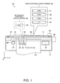
- FIG. 1 is a schematic diagram of an inkjet printer 1 having a discharge inspection device according to first embodiment of the invention.
- the inkjet printer 10 has a carriage 20 on which ink cartridges 11 to 14 are installed.
- the ink cartridges 11 to 14 respectively store yellow (Y), magenta (M), cyan (C), and black (K) colored inks as the recording fluid.
- the carriage 20 travels in a main scanning direction (x-axis direction) and the print medium 25 travels in the subscanning direction (y-axis direction).
- the inkjet printer 10 discharges ink droplets onto the print medium 25 in the z-axis direction from a print head 30 on the bottom of the carriage 20.
- the carriage 20 is attached to a carriage belt 41 that is driven in a loop by a carriage motor 40. As the carriage belt 41 revolves, the carriage 20 moves in the main scanning direction along a guide 21 fixed to a frame 17.
- the print medium 25 also moves in the subscanning direction when transportation rollers not shown are driven by a drive motor 26 attached to the frame 17.
- ink droplets are discharged from a plurality of nozzles disposed to the print head for discharging the different colors of ink, and a particular image or other content is printed on the print medium 25. If there are any nozzles from which the ink cannot be discharged, the image will not be correctly printed on the print medium 25.
- the inkjet printer 10 therefore executes a discharge inspection operation for determining whether or not ink droplets are discharged from each of the plural nozzles.
- This discharge inspection moves the carriage 20 to the position of an inspection box 70 that is disposed to the inkjet printer 10 as a recording fluid receiving unit, and detects if ink droplets are discharged from each of the nozzles.
- this discharge inspection detects a faulty nozzle, that is, a nozzle from which ink droplets are not discharged, the carriage 20 is moved to the position of a cleaning box 18 provided in the inkjet printer 10 to clean the nozzles by means of a prescribed cleaning process.
- a vibration sensor 80 is disposed to the inspection box 70.
- the vibration sensor 80 can detect vibration caused by impact or shaking externally applied to the inkjet printer 10.
- main control circuit board 50 (referred to below as the main circuit board) disposed to the frame 17, and a secondary control circuit board 60 (referred to below as the secondary circuit board) disposed to the edge of the carriage 20.
- secondary circuit board 60 (referred to below as the secondary circuit board) disposed to the edge of the carriage 20.
- the main circuit board 50 is populated with a CPU 51 for controlling operation of the inkjet printer 10, a ROM 52 storing a program related to these operations, RAM 53 for temporarily storing data required for these operations, and an interface 54 enabling data communication with the secondary circuit board 60 and data communication with a user computer or other external device.
- the discharge inspection program for inspecting ink discharge as described below is stored in the ROM 52.
- An ASIC 61 containing the logic circuits and other devices for executing specific operations related to the discharge inspection is mounted on the secondary circuit board 60.
- the CPU 51 reads the discharge inspection program stored in ROM 52 and exchanges signal data with the ASIC 61 so that the CPU 51 and ASIC 61 cooperatively execute the predetermined tasks of the discharge inspection operation.
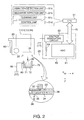
- FIG. 2 schematically describes the configuration of the discharge inspection device.
- FIG. 2 shows the configuration of a device for discharging charged ink from the plural nozzles of the print head 30 and determining if ink is discharged from each of the nozzles.
- ink supplied from the ink cartridges 11 to 14 to the print head 30 is discharged as ink droplets 39 from the print head 30 as shown in FIG. 2 .
- a mechanism for producing ink discharge pressure in each of the plural nozzles of the print head 30 is rendered as shown in the enlarged drawing in FIG. 2 .
- the member 33 on which the piezoelectric device 32 is formed is pushed in the direction of the arrow (the z-axis direction).
- ink 38 supplied from the ink cartridge 11, for example is pressurized, ink droplets 39 are discharged from an ink nozzle 35 disposed to the nozzle plate 34. More specifically, by applying voltage to the piezoelectric device 32 corresponding to the nozzle to be inspected, whether or not ink droplets 39 are discharged from that nozzle can be checked.
- a voltage that causes the piezoelectric device 32 to deform (also referred to as the drive voltage below) is output from a driver circuit 31 as a drive signal applied to the piezoelectric device 32.
- the driver circuit 31 is disposed in the carriage 20 near the print head 30, is connected to the secondary circuit board 60 by a wiring member not shown, and operates according to an output signal from the ASIC 61.
- the discharged ink droplets 39 land on an electrode member 71 disposed in the inspection box 70.
- the electrode member 71 is made from a stainless steel or other type of metal mesh rendering the ink droplet 39 landing area.
- the ink droplets 39 that land pass through the electrode member 71 and are absorbed by an ink absorber 72 such as a synthetic sponge.
- the electrode member 71 is electrically connected to the frame 17 by a wiring member 66.
- a voltage generating circuit 62 is mounted on the secondary circuit board 60 on which the ASIC 61 is disposed. During the discharge inspection, the ASIC 61 causes the voltage generating circuit 62, one end of which is connected (grounded) to the frame 17, to operate. The ASIC 61 applies a predetermined voltage to the frame 17, and then applies a predetermined voltage to the print head 30 through a resistance 64 and wiring member 65. The part of the print head 30 to which the voltage is applied is a part (such as the nozzle plate 34) that is electrically conductive with the ink 38.
- the CPU 51 functions as a vibration detection unit 51 a, discharge inspection unit 51b, cleaning unit 51c, and control unit 51 d by controlling the ROM 52, RAM 53, and ASIC 61.
- the vibration detection unit 51a uses a vibration sensor 80 disposed in the inspection box 70 to detect vibration produced in the inspection box 70 by an external shock or shaking of the inkjet printer 10 as vibration information. The vibration detection unit 51a then outputs a vibration detection value denoting the detected vibration information as a signal indicative of the degree of a detected vibration.
- the vibration sensor 80 is an acceleration sensor that detects acceleration caused by vibration of the inspection box 70, but the vibration sensor 80 is not limited to an acceleration sensor and may be rendered using a gyroscopic sensor, a pressure sensor, a photodetector, a proximity sensor, a mechanical contact sensor, or other device that can detect vibration. Note that if a mechanical contact sensor is used, it outputs a signal denoting that a predetermined threshold level has been exceeded only when it detects vibration that will adversely affect the discharge inspection.
- the discharge inspection unit 51 b inspects ink discharge from the plural nozzles of the print head 30, and determines whether or not ink droplets 39 are discharged from each of the nozzles.
- the discharge inspection unit 51 b does this by driving the piezoelectric device 32 and measuring the voltage change between the print head 30 and electrode member 71. If this measurement detects a voltage change for the nozzle being inspected when the piezoelectric device 32 is driven, the discharge inspection unit 51b confirms ink droplet discharge, but if a voltage change is not detected, it determines that ink droplets were not discharged.
- the cleaning unit 51c apples the cleaning process to the nozzles that need cleaning based on the result of the discharge inspection of each nozzle by the discharge inspection unit 51 b.
- the control unit 51d controls the overall operation of the inkjet printer 10, including the vibration detection unit 51a, discharge inspection unit 51b, and cleaning unit 51c.
- the control unit 51d controls whether or not the discharge inspection unit 51 b executes the discharge inspection based on the vibration detection value output by the vibration detection unit 51 a.
- the control unit 51 d compares the detected vibration detection value with a predetermined threshold value to determine whether to execute the discharge inspection. This threshold value defines the vibration level that can be expected to adversely affect the discharge inspection, and is stored in ROM 52, for example.
- a method of driving the piezoelectric device that causes ink droplets to be discharged from the nozzle to be inspected is described next.
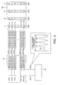
- FIG. 3 describes this method of driving the piezoelectric device that causes ink droplets to be discharged.
- the print head 30 has nozzle rows 35Y, 35M, 35C, and 35K corresponding to ink colors yellow (Y), magenta (M), cyan (C), and black (K).
- the print head 30 has a total of 720 nozzles to be inspected.
- the main circuit board 50 produces a source signal ODRV and a print signal PRTn identifying the nozzle to discharge ink droplets.
- the source signal ODRV is a signal unit of four pulses Pv, P1, P2, P3 (the peaks in FIG. 3 ) that repeat in each segment printing an image equal to one pixel (the time required for the carriage 20 to cross an interval of one pixel is also called a segment).
- Pulse signal Pv causes the ink to vibrate by causing the piezoelectric device to vibrate so that ink inside the nozzle does not solidify.
- Pulse signals P1, P2 and P3 cause one ink droplet to be discharged from the nozzle.
- Pulse signal P1 causes a small dot
- pulse signal P2 causes a medium size dot
- pulse signal P3 causes a large dot to be formed on the print medium.
- the print signal PRTn is the signal that selects the nozzle that discharges ink and the print data (whether a dot is printed or not and the gray level of the dot) based on the print image, and selectively supplies the drive signal for the selected nozzle.
- the print signal PRTn is the nozzle selection signal that selectively supplies the drive signal to the nozzle that is to discharge ink for inspection.
- the mask circuit is configured so that the pulse signal selected from the source signal by the print signal PRTn is output to the piezoelectric device corresponding to the nozzle identified by the same print signal PRTn.
- the mask circuit is configured so that the pulse signal selected from among the pulse signals Pv, P1, P2, P3 by the print signal is output to the piezoelectric device corresponding to the selection inspection nozzle as the drive signal DRVn.
- the discharge inspection process repeats a procedure outputting the drive signal DRVn generated by the mask circuit to the inspection nozzle selected by the nozzle selection signal for each of the 180 nozzles in one nozzle row. This process is then applied to all of the nozzle rows Y, M, C, and K so that the corresponding piezoelectric devices are sequentially driven and ink discharge is inspected for all of the nozzles in the print head.
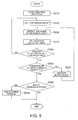
- FIG. 4 is a flow chart describing the operation of the discharge inspection device according to this first embodiment of the invention. The operation described in this flow chart is executed at the discharge inspection timing of the plural nozzles in the print head, such as when the power is turned on, before a print job starts, during the print job, and when a print job ends.
- Operation starts with the vibration detection unit 51a of the CPU 51 starting detection of vibration in the inspection box 70 by means of the vibration sensor 80 in step S110.
- the discharge inspection unit 51b of the CPU 51 applies the discharge inspection to the plural nozzles of the print head 30.
- the vibration detection value output by the vibration sensor 80 for the inspection box 70 is acquired by the control unit 51 d of the CPU 51 in step S130.
- the vibration detection value acquired here represents the vibration produced in the inspection box 70 when ink discharge is inspected in step S120.
- step S140 the control unit 51d of the CPU 51 compares the vibration detection value acquired in step S130 with a predetermined threshold value. If the vibration detection value is less than the predetermined threshold value, the control unit 51d determines that vibration adversely affecting the discharge inspection was not applied to the inspection box 70 during the discharge inspection, and control goes to step S150. More specifically, if the discharge inspection was completed normally without being subject to vibration that could adversely affect the result of the discharge inspection, control goes to the process determining if there are any faulty nozzles that are not discharging correctly.
- the control unit 51 d determines that vibration adversely affecting the discharge inspection was applied to the inspection box 70 during the discharge inspection, and control returns to step S120. More specifically, if the discharge inspection was not completed without being subject to vibration that could adversely affect the result of the discharge inspection, the discharge inspection is repeated.
- step S150 the control unit 51 d of the CPU 51 determines if there are any faulty nozzles that are not discharging correctly based on the result of the discharge inspection process executed in step S120. If there are no faulty nozzles, processing by the discharge inspection device ends.
- control goes to step S160 and the cleaning unit 51 c of the CPU 51 applies the cleaning process to the faulty nozzles determined to need cleaning, and processing by the discharge inspection device then ends.
- nozzles that discharge normally may be falsely determined to be faulty nozzles, and faulty nozzles that do not discharge normally may be falsely determined to be functioning normally. As a result, unnecessary cleaning operations may be executed or necessary cleaning operations may not be executed.
- vibration produced in the inspection box 70 is detected using a vibration sensor 80 during the discharge inspection of the plural nozzles in the print head 30. After the discharge inspection is completed, whether vibration adversely affecting the results of the discharge inspection was detected is verified. If such vibration was not detected, the presence of any faulty nozzles is detected, and the cleaning process is then applied if faulty nozzles are detected. However, if such vibration was detected, the cleaning process is not executed and the discharge inspection is repeated.
- the cleaning process does not run when the discharge inspection is subject to vibration adversely affecting the result, executing the cleaning process based on incorrect discharge inspection results can be prevented. Furthermore, because the discharge inspection is repeated, the discharge inspection is ultimately completed under conditions not subject to the effects of vibration, and the correct discharge inspection result can be acquired.
- a discharge inspection device according to a second embodiment of the invention is described next.
- FIG. 5 is a flow chart describing the operation of a discharge inspection device according to a second embodiment of the invention. The operation described in FIG. 5 starts at the same timing as the discharge inspection process described in the flow chart of the first embodiment shown in FIG. 4 .
- Operation starts with the vibration detection unit 51 a of the CPU 51 starting detection of vibration in the inspection box 70 by means of the vibration sensor 80 in step S210.
- the control unit 51d of the CPU 51 sets the first nozzle group of the print head 30 for inspecting ink discharge.
- the nozzle groups of the print head 30 are the groups of nozzles in the nozzle rows 35Y, 35M, 35C, and 35K corresponding to ink colors yellow (Y), magenta (M), cyan (C), and black (K) as shown in FIG. 3 .
- the nozzle group to which the discharge inspection is first applied is nozzle group 35Y in this embodiment.
- nozzle group 35K may be the first nozzle group that is inspected, and the configuration of the nozzle groups may be determined according to the number of ink colors or the number nozzles.
- step S230 the discharge inspection unit 51 b of the CPU 51 applies the discharge inspection process to the nozzle group selected for inspection.
- the control unit 51d of the CPU 51 acquires the vibration detection value detected by the vibration sensor 80 for the inspection box 70.
- the vibration detection value acquired here represents the vibration produced in the inspection box 70 when ink discharge is inspected in step S120.
- step S250 the control unit 51d of the CPU 51 compares the vibration detection value acquired in step S240 with a predetermined threshold value. If the vibration detection value is less than the predetermined threshold value, the control unit 51d determines that vibration adversely affecting the discharge inspection was not applied to the inspection box 70 during the discharge inspection, and control goes to step S260.
- the control unit 51 d determines that vibration adversely affecting the discharge inspection was applied to the inspection box 70 during the discharge inspection, and control returns to step S220. More specifically, if the discharge inspection was not completed without being subject to vibration that could adversely affect the result of the discharge inspection, inspecting ink discharge from the remaining nozzle groups of the print head 30 is stopped, and the discharge inspection process is applied again to the first nozzle group.
- step S260 the control unit 51 d of the CPU 51 determines if discharge inspection has been completed for all nozzle groups of the print head 30. If discharge inspection of all nozzle groups is completed, control goes to step S280 to determine if there are any faulty nozzles that are not discharging correctly.
- step S270 the control unit 51d of the CPU 51 sets the next nozzle group to be inspected. Control then returns to step S230 and the discharge inspection process is applied to the next nozzle group.
- step S280 the control unit 51 d of the CPU 51 determines if there are any faulty nozzles that are not discharging correctly based on the result of the discharge inspection process applied to each of the nozzle groups in step S230. If there are no faulty nozzles, processing by the discharge inspection device ends.
- control goes to step S290 and the cleaning unit 51c of the CPU 51 applies the cleaning process to the faulty nozzles determined to need cleaning, and processing by the discharge inspection device then ends.
- the discharge inspection device divides the nozzles of the print head 30 into a plurality of nozzle groups and applies the discharge inspection process to each nozzle group.
- vibration adversely affecting the results of the discharge inspection of each nozzle group was detected is then verified. If vibration adversely affecting the discharge inspection result was detected, discharge inspection of the remaining nozzle groups is stopped and the discharge inspection is repeated from the first nozzle group.
- a discharge inspection device according to a third embodiment of the invention is described next.
- FIG. 6 is a flow chart describing the operation of a discharge inspection device according to a third embodiment of the invention. The operation described in FIG. 6 starts at the same timing as the discharge inspection process described in the flow chart of the first embodiment shown in FIG. 4 .
- Operation starts with the vibration detection unit 51 a of the CPU 51 starting detection of vibration in the inspection box 70 by means of the vibration sensor 80 in step S310.
- the control unit 51 d of the CPU 51 acquires the detected vibration detection value of the inspection box 70. Differing from the discharge inspection device of the first embodiment, the vibration detection value acquired here represents vibration detected in the inspection box 70 before the discharge inspection process.
- step S330 the control unit 51d of the CPU 51 compares the vibration detection value acquired in step S320 with a predetermined threshold value. If the vibration detection value is less than the predetermined threshold value, the control unit 51d determines that vibration adversely affecting the discharge inspection was not applied to the inspection box 70 before the discharge inspection, and control goes to step S340. More specifically, operation proceeds to the discharge inspection process only when there is no vibration adversely affecting the discharge inspection result.
- control unit 51d determines that vibration adversely affecting the discharge inspection was applied to the inspection box 70 before the discharge inspection, and control returns to step S320. More specifically, if there is vibration adversely affecting the discharge inspection result, this embodiment of the invention waits until such vibration is not detected.
- step S340 the discharge inspection unit 51b of the CPU 51 detects ink discharge from the plural nozzles of the print head 30.
- the vibration detection value output by the vibration sensor 80 for the inspection box 70 is acquired by the control unit 51d of the CPU 51 in step S350.
- the vibration detection value acquired here represents the vibration produced in the inspection box 70 when ink discharge is inspected in step S340.
- step S360 the control unit 51d of the CPU 51 compares the vibration detection value acquired in step S350 with a predetermined threshold value. If the vibration detection value is less than the predetermined threshold value, the control unit 51d determines that vibration adversely affecting the discharge inspection was not applied to the inspection box 70 during the discharge inspection, and control goes to step S370. More specifically, if the discharge inspection was completed normally without being subject to vibration that could adversely affect the result of the discharge inspection, control goes to the process determining if there are any faulty nozzles that are not discharging correctly.
- the control unit 51 d determines that vibration adversely affecting the discharge inspection was applied to the inspection box 70 during the discharge inspection, and control returns to step S320. More specifically, if the discharge inspection was not completed without being subject to vibration that could adversely affect the result of the discharge inspection, the discharge inspection is repeated after the vibration stops.
- step S370 the control unit 51 d of the CPU 51 determines if there are any faulty nozzles that are not discharging correctly based on the result of the discharge inspection process executed in step S340. If there are no faulty nozzles, processing by the discharge inspection device ends.
- control goes to step S380 and the cleaning unit 51c of the CPU 51 applies the cleaning process to the faulty nozzles determined to need cleaning, and processing by the discharge inspection device then ends.
- This embodiment of the invention describes applying the discharge inspection process to all nozzles of the print head 30 as a single group in the same way as described in the flow chart of the first embodiment shown in FIG. 4 .
- the invention is not so limited, however, and the nozzles may be divided into nozzle groups and the ink discharge inspection may be applied by nozzle group as described in the flow chart of the second embodiment shown in FIG. 5 .
- the discharge inspection device uses the vibration sensor 80 to detect vibration in the inspection box 70 before inspecting ink discharge from the plural nozzles of the print head 30. If vibration adversely affecting the discharge inspection result is detected, operation waits until the vibration stops.
- a vibration sensor 80 is disposed to the inspection box 70 of the inkjet printer 10 in the embodiments of the invention described above.
- the location where the vibration sensor 80 is disposed is not so limited, however, and the vibration sensor 80 can be located wherever vibration adversely affecting the discharge inspection result can be detected.
- FIG. 7 shows an example of a configuration in which the vibration sensor 80 is disposed to the frame 17 of the inkjet printer 10. By thus mounting the vibration sensor 80 on the frame 17, the effect of vibration produced by the drive units of the inkjet printer 10 can be reduced and vibration can be reliably detected.
- the invention is described above using an inkjet printer having the discharge inspection device of the invention.
- the invention is not so limited, however, and the discharge inspection device described in the foregoing embodiments may be rendered in any type of device that records patterns, images, drawings, text, or other content on a recording medium by discharging recording fluid using an inkjet method.
- the invention may be used in inkjet recording devices that discharge recording fluid to a glass substrate or resin substrate to form a wiring pattern, a color filter, or pixels on an organic electroluminescent display, for example.
Landscapes
- Ink Jet (AREA)
Applications Claiming Priority (1)
| Application Number | Priority Date | Filing Date | Title |
|---|---|---|---|
| JP2007305359A JP5281275B2 (ja) | 2007-11-27 | 2007-11-27 | 吐出検査装置、記録装置、吐出検査方法及び吐出検査プログラム |
Publications (3)
| Publication Number | Publication Date |
|---|---|
| EP2065201A2 true EP2065201A2 (fr) | 2009-06-03 |
| EP2065201A3 EP2065201A3 (fr) | 2009-12-16 |
| EP2065201B1 EP2065201B1 (fr) | 2011-04-06 |
Family
ID=40394124
Family Applications (1)
| Application Number | Title | Priority Date | Filing Date |
|---|---|---|---|
| EP08019548A Ceased EP2065201B1 (fr) | 2007-11-27 | 2008-11-07 | Mécanisme d'inspection de décharge, dispositif d'enregistrement, procédé d'inspection de décharge et programme d'inspection de décharge |
Country Status (5)
| Country | Link |
|---|---|
| US (1) | US8087294B2 (fr) |
| EP (1) | EP2065201B1 (fr) |
| JP (1) | JP5281275B2 (fr) |
| CN (1) | CN101444992B (fr) |
| DE (1) | DE602008005990D1 (fr) |
Families Citing this family (7)
| Publication number | Priority date | Publication date | Assignee | Title |
|---|---|---|---|---|
| JP5533237B2 (ja) * | 2010-05-18 | 2014-06-25 | セイコーエプソン株式会社 | 液体吐出装置、及び、吐出検査方法 |
| WO2012084686A1 (fr) * | 2010-12-21 | 2012-06-28 | Oce-Technologies B.V. | Procédé pour déterminer des performances d'unité de maintenance |
| JP5648540B2 (ja) * | 2011-03-15 | 2015-01-07 | セイコーエプソン株式会社 | プリンターの制御方法及びプリンター |
| JP5891713B2 (ja) * | 2011-11-02 | 2016-03-23 | セイコーエプソン株式会社 | 記録装置、記録装置の制御方法、及び、プログラム |
| US8919921B2 (en) * | 2012-11-15 | 2014-12-30 | Ricoh Company, Ltd. | Image forming apparatus |
| CN105880502A (zh) * | 2016-04-18 | 2016-08-24 | 马鞍山尚元冶金科技有限公司 | 一种连铸二冷区喷嘴工作状态的实时检测装置及方法 |
| CN110794168B (zh) * | 2019-10-29 | 2021-12-24 | 歌尔股份有限公司 | 一种压电喷胶系统的检测方法和装置 |
Citations (1)
| Publication number | Priority date | Publication date | Assignee | Title |
|---|---|---|---|---|
| JPH11170569A (ja) | 1997-10-07 | 1999-06-29 | Hewlett Packard Co <Hp> | インク滴検出器 |
Family Cites Families (11)
| Publication number | Priority date | Publication date | Assignee | Title |
|---|---|---|---|---|
| JPH02239943A (ja) * | 1989-03-14 | 1990-09-21 | Inax Corp | インクジエットプリンタの目詰検出装置 |
| JP3190486B2 (ja) * | 1993-07-19 | 2001-07-23 | キヤノン株式会社 | インクジェット記録装置および該装置用インクジェット記録ヘッド |
| JPH08336986A (ja) | 1995-06-15 | 1996-12-24 | Canon Inc | インク吐出監視装置 |
| JPH11104535A (ja) * | 1997-08-04 | 1999-04-20 | Omron Corp | ノズル詰まり検知方法およびノズル詰まり検知装置 |
| US6513434B1 (en) * | 1999-05-17 | 2003-02-04 | Fuji Photo Film Co., Ltd. | On-press recording type lithographic printing method and apparatus |
| JP2002166552A (ja) * | 2000-11-30 | 2002-06-11 | Canon Inc | 液体吐出ヘッド、液体吐出記録装置、および移動体に搭載された前記記録装置での液体吐出記録方法 |
| CN1286645C (zh) * | 2003-02-28 | 2006-11-29 | 精工爱普生株式会社 | 液滴喷出装置及液滴喷出头的喷出异常检测、判断方法 |
| DE602004021867D1 (de) * | 2003-02-28 | 2009-08-20 | Seiko Epson Corp | Tröpfchenausstossgerät und Verfahren zur Ausstossausfallbeseitigung |
| JP2007001160A (ja) * | 2005-06-24 | 2007-01-11 | Seiko Epson Corp | インクジェット記録装置 |
| JP2007030221A (ja) * | 2005-07-22 | 2007-02-08 | Noritsu Koki Co Ltd | インクジェットプリンタ |
| JP2007144720A (ja) * | 2005-11-25 | 2007-06-14 | Canon Inc | プリンタ |
-
2007
- 2007-11-27 JP JP2007305359A patent/JP5281275B2/ja not_active Expired - Fee Related
-
2008
- 2008-11-07 DE DE602008005990T patent/DE602008005990D1/de active Active
- 2008-11-07 EP EP08019548A patent/EP2065201B1/fr not_active Ceased
- 2008-11-21 US US12/313,536 patent/US8087294B2/en not_active Expired - Fee Related
- 2008-11-25 CN CN2008101791175A patent/CN101444992B/zh not_active Expired - Fee Related
Patent Citations (1)
| Publication number | Priority date | Publication date | Assignee | Title |
|---|---|---|---|---|
| JPH11170569A (ja) | 1997-10-07 | 1999-06-29 | Hewlett Packard Co <Hp> | インク滴検出器 |
Also Published As
| Publication number | Publication date |
|---|---|
| US20090133503A1 (en) | 2009-05-28 |
| CN101444992B (zh) | 2010-12-15 |
| JP5281275B2 (ja) | 2013-09-04 |
| EP2065201B1 (fr) | 2011-04-06 |
| US8087294B2 (en) | 2012-01-03 |
| EP2065201A3 (fr) | 2009-12-16 |
| DE602008005990D1 (de) | 2011-05-19 |
| CN101444992A (zh) | 2009-06-03 |
| JP2009126119A (ja) | 2009-06-11 |
Similar Documents
| Publication | Publication Date | Title |
|---|---|---|
| EP2065201B1 (fr) | Mécanisme d'inspection de décharge, dispositif d'enregistrement, procédé d'inspection de décharge et programme d'inspection de décharge | |
| JP5740935B2 (ja) | 画像形成装置、及び、画像形成方法 | |
| US7771001B2 (en) | Liquid discharge apparatus, method for controlling the same, and program for controlling the same | |
| CN113858827B (zh) | 印刷装置及印刷方法 | |
| CN104494311A (zh) | 液体喷出装置以及喷出检查方法 | |
| US20120256980A1 (en) | Printing apparatus | |
| KR20070057903A (ko) | 화상 형성 장치, 화상 형성 방법, 화상 형성 프로그램을 기록한 기록 매체, 데이터 생성 장치, 데이터 생성 방법, 및 데이터 생성 프로그램을 기록한 기록 매체 | |
| JP2012203425A (ja) | 画像処理装置、画像処理方法、および印刷装置 | |
| JP2011255594A (ja) | 液体噴射装置、及び、液体噴射方法 | |
| US20100245442A1 (en) | Method for detecting defective liquid ejection, and defective liquid ejection detection device | |
| US9796176B2 (en) | Image forming apparatus, method of forming image, and non-transitory recording medium | |
| JP7215221B2 (ja) | ヘッドユニット、及び、液体吐出装置 | |
| JP2010240911A (ja) | 吐出不良検出方法及び吐出不良検出装置 | |
| JP2016150538A (ja) | 印刷装置、印刷装置の制御方法、および、印刷装置の制御プログラム | |
| JP2010221582A (ja) | 吐出不良検出方法及び吐出不良検出装置 | |
| JP4862547B2 (ja) | ノズル検査装置、インクジェットプリンタ、ノズル検査方法、およびノズル検査プログラム | |
| US12220912B2 (en) | Printing apparatus, display method, and display system | |
| JP5120444B2 (ja) | 吐出検査装置、記録装置、吐出検査方法及び吐出検査プログラム | |
| JP5750841B2 (ja) | 印刷装置 | |
| JP2012091526A (ja) | ノズル検査装置、ノズル検査方法、および検査プログラム | |
| JP6531484B2 (ja) | 液体を吐出する装置、画像データを処理する方法、プログラム | |
| JP2008105335A (ja) | 吐出検査装置、吐出検査方法および検査プログラム | |
| JP4962642B2 (ja) | ノズル検査装置、ノズル検査方法、および検査プログラム | |
| JP2008023886A (ja) | ノズル検査装置、ノズル検査方法、および検査プログラム | |
| JP2008087201A (ja) | 吐出検査装置、吐出検査方法、および検査プログラム |
Legal Events
| Date | Code | Title | Description |
|---|---|---|---|
| PUAI | Public reference made under article 153(3) epc to a published international application that has entered the european phase |
Free format text: ORIGINAL CODE: 0009012 |
|
| AK | Designated contracting states |
Kind code of ref document: A2 Designated state(s): AT BE BG CH CY CZ DE DK EE ES FI FR GB GR HR HU IE IS IT LI LT LU LV MC MT NL NO PL PT RO SE SI SK TR |
|
| AX | Request for extension of the european patent |
Extension state: AL BA MK RS |
|
| PUAL | Search report despatched |
Free format text: ORIGINAL CODE: 0009013 |
|
| AK | Designated contracting states |
Kind code of ref document: A3 Designated state(s): AT BE BG CH CY CZ DE DK EE ES FI FR GB GR HR HU IE IS IT LI LT LU LV MC MT NL NO PL PT RO SE SI SK TR |
|
| AX | Request for extension of the european patent |
Extension state: AL BA MK RS |
|
| 17P | Request for examination filed |
Effective date: 20100503 |
|
| GRAP | Despatch of communication of intention to grant a patent |
Free format text: ORIGINAL CODE: EPIDOSNIGR1 |
|
| AKX | Designation fees paid |
Designated state(s): DE FR GB IT |
|
| GRAS | Grant fee paid |
Free format text: ORIGINAL CODE: EPIDOSNIGR3 |
|
| GRAA | (expected) grant |
Free format text: ORIGINAL CODE: 0009210 |
|
| AK | Designated contracting states |
Kind code of ref document: B1 Designated state(s): DE FR GB IT |
|
| REG | Reference to a national code |
Ref country code: GB Ref legal event code: FG4D |
|
| REF | Corresponds to: |
Ref document number: 602008005990 Country of ref document: DE Date of ref document: 20110519 Kind code of ref document: P |
|
| REG | Reference to a national code |
Ref country code: DE Ref legal event code: R096 Ref document number: 602008005990 Country of ref document: DE Effective date: 20110519 |
|
| PLBE | No opposition filed within time limit |
Free format text: ORIGINAL CODE: 0009261 |
|
| STAA | Information on the status of an ep patent application or granted ep patent |
Free format text: STATUS: NO OPPOSITION FILED WITHIN TIME LIMIT |
|
| 26N | No opposition filed |
Effective date: 20120110 |
|
| REG | Reference to a national code |
Ref country code: DE Ref legal event code: R097 Ref document number: 602008005990 Country of ref document: DE Effective date: 20120110 |
|
| REG | Reference to a national code |
Ref country code: FR Ref legal event code: PLFP Year of fee payment: 8 |
|
| REG | Reference to a national code |
Ref country code: FR Ref legal event code: PLFP Year of fee payment: 9 |
|
| REG | Reference to a national code |
Ref country code: FR Ref legal event code: PLFP Year of fee payment: 10 |
|
| REG | Reference to a national code |
Ref country code: FR Ref legal event code: PLFP Year of fee payment: 11 |
|
| PGFP | Annual fee paid to national office [announced via postgrant information from national office to epo] |
Ref country code: FR Payment date: 20201013 Year of fee payment: 13 Ref country code: DE Payment date: 20201028 Year of fee payment: 13 Ref country code: IT Payment date: 20201013 Year of fee payment: 13 Ref country code: GB Payment date: 20201028 Year of fee payment: 13 |
|
| REG | Reference to a national code |
Ref country code: DE Ref legal event code: R119 Ref document number: 602008005990 Country of ref document: DE |
|
| GBPC | Gb: european patent ceased through non-payment of renewal fee |
Effective date: 20211107 |
|
| PG25 | Lapsed in a contracting state [announced via postgrant information from national office to epo] |
Ref country code: GB Free format text: LAPSE BECAUSE OF NON-PAYMENT OF DUE FEES Effective date: 20211107 Ref country code: DE Free format text: LAPSE BECAUSE OF NON-PAYMENT OF DUE FEES Effective date: 20220601 |
|
| PG25 | Lapsed in a contracting state [announced via postgrant information from national office to epo] |
Ref country code: FR Free format text: LAPSE BECAUSE OF NON-PAYMENT OF DUE FEES Effective date: 20211130 |
|
| PG25 | Lapsed in a contracting state [announced via postgrant information from national office to epo] |
Ref country code: IT Free format text: LAPSE BECAUSE OF NON-PAYMENT OF DUE FEES Effective date: 20211130 |