EP2065252A2 - Cloison déplaçable pour véhicule - Google Patents
Cloison déplaçable pour véhicule Download PDFInfo
- Publication number
- EP2065252A2 EP2065252A2 EP08170162A EP08170162A EP2065252A2 EP 2065252 A2 EP2065252 A2 EP 2065252A2 EP 08170162 A EP08170162 A EP 08170162A EP 08170162 A EP08170162 A EP 08170162A EP 2065252 A2 EP2065252 A2 EP 2065252A2
- Authority
- EP
- European Patent Office
- Prior art keywords
- bulkhead
- vehicle
- latched
- panel
- end panel
- Prior art date
- Legal status (The legal status is an assumption and is not a legal conclusion. Google has not performed a legal analysis and makes no representation as to the accuracy of the status listed.)
- Granted
Links
- 238000000034 method Methods 0.000 claims description 7
- 230000007246 mechanism Effects 0.000 description 26
- 238000012546 transfer Methods 0.000 description 11
- 230000009466 transformation Effects 0.000 description 10
- 230000008901 benefit Effects 0.000 description 5
- 238000009434 installation Methods 0.000 description 2
- 238000004806 packaging method and process Methods 0.000 description 2
- 230000008569 process Effects 0.000 description 2
- 238000007789 sealing Methods 0.000 description 2
- 238000013461 design Methods 0.000 description 1
- 238000010586 diagram Methods 0.000 description 1
- 230000009977 dual effect Effects 0.000 description 1
- 230000005484 gravity Effects 0.000 description 1
- 238000012986 modification Methods 0.000 description 1
- 230000004048 modification Effects 0.000 description 1
- 230000003014 reinforcing effect Effects 0.000 description 1
- 238000000926 separation method Methods 0.000 description 1
- 230000001131 transforming effect Effects 0.000 description 1
- 238000013519 translation Methods 0.000 description 1
Images











Classifications
-
- B—PERFORMING OPERATIONS; TRANSPORTING
- B60—VEHICLES IN GENERAL
- B60P—VEHICLES ADAPTED FOR LOAD TRANSPORTATION OR TO TRANSPORT, TO CARRY, OR TO COMPRISE SPECIAL LOADS OR OBJECTS
- B60P3/00—Vehicles adapted to transport, to carry or to comprise special loads or objects
- B60P3/42—Vehicles adapted to transport, to carry or to comprise special loads or objects convertible from one use to a different one
- B60P3/423—Vehicles adapted to transport, to carry or to comprise special loads or objects convertible from one use to a different one from transport of persons to transport of goods
-
- B—PERFORMING OPERATIONS; TRANSPORTING
- B60—VEHICLES IN GENERAL
- B60P—VEHICLES ADAPTED FOR LOAD TRANSPORTATION OR TO TRANSPORT, TO CARRY, OR TO COMPRISE SPECIAL LOADS OR OBJECTS
- B60P7/00—Securing or covering of load on vehicles
- B60P7/06—Securing of load
- B60P7/135—Securing or supporting by load bracing means
- B60P7/14—Securing or supporting by load bracing means the load bracing means comprising a movable bulkhead
-
- B—PERFORMING OPERATIONS; TRANSPORTING
- B60—VEHICLES IN GENERAL
- B60R—VEHICLES, VEHICLE FITTINGS, OR VEHICLE PARTS, NOT OTHERWISE PROVIDED FOR
- B60R21/00—Arrangements or fittings on vehicles for protecting or preventing injuries to occupants or pedestrians in case of accidents or other traffic risks
- B60R21/02—Occupant safety arrangements or fittings, e.g. crash pads
- B60R21/026—Rigid partitions inside vehicles, e.g. between passengers and load compartments
Definitions
- This invention relates motor vehicles and in particular to a moveable bulkhead for use in a van.
- a light commercial vehicle such as a van to have maximum flexibility and a dual-usage van incorporating both a crew cab and a full load-length cargo area satisfies this need.
- Such a dual-usage vehicle can be used to transport workers to say a building site in the morning, be used to transport large goods during the working day and then be used to take the workers back home in the evening or as a multi-use vehicle that can operate as family transport or as a business van for owner operators.
- a moveable bulkhead with collapsible seats is known from, for example, GB-A-2,384,464 .
- This arrangement provides a full uncompromised seating position in one condition and a tightly packaged stowed condition but has the disadvantage that the seats are mounted to the bulkhead.
- the mounting of the seats to the bulkhead is disadvantageous because it requires a more significant structure to be used for the bulkhead resulting in increased vehicle weight and places unique and expensive requirements on the bulkhead mechanism and latches in order to meet safety standards particularly seat belt standards.
- a moveable bulkhead for a motor vehicle comprising a number of panels hingedly connected together so as to permit each panel to rotate about a vertical axis relative to an adjacent panel and latching means to selectively secure the panels forming the bulkhead in the motor vehicle so as to prevent rotation of the panels and separate a cargo carrying compartment of the motor vehicle from a passenger carrying compartment of the motor vehicle wherein the bulkhead is latchable in at least a forward position and a rear position and is transformable between the two positions by the sequential un-latching, rotation and re-latching of the panels.
- the bulkhead may include at least first and second end panels and a centre panel and the bulkhead may be transformed to move it between the forward and rear positions such that the first end panel is a left hand end panel when the bulkhead is latched in the forward position and is a right hand end panel when the bulkhead is latched in the rear position and the second end panel is a left hand end panel when the bulkhead is latched in the rear position and is a right hand end panel when the bulkhead is latched in the forward position.
- the width of the centre panel may be substantially equal to the distance between the forward and rear positions of the bulkhead so as to permit the latching means to be re-latched when the centre panel has been rotated through 90 degrees.
- the bulkhead may include at least first and second end panels each of which extends forwardly when the bulkhead is latched in a forward position in the vehicle and extends rearwardly when the bulkhead is latched in a rear position in the vehicle.
- Each of the first and second end panels may be "L"-shaped having wing portions that are arranged longitudinally with respect to the vehicle when the bulkhead is latched in the vehicle in either of the forward and rear positions and body portions that are arranged transversely with respect to the vehicle when the bulkhead is latched in the vehicle in either of the forward and rear positions.
- the bulkhead may be further latchable in a side-locker position.
- Each of the first and second end panels may be "L"-shaped having wing portions that are arranged longitudinally with respect to the vehicle when the bulkhead is latched in the vehicle in the side locker position and body portions that are arranged transversely with respect to the vehicle when the bulkhead is latched in the vehicle in the side locker position.
- the moveable bulkhead may comprise of the first end panel which extends forwardly when the bulkhead is latched in the forward position in the vehicle and extends rearwardly when the bulkhead is latched in the rear position, the second end panel which extends forwardly when the bulkhead is latched in a forward position in the vehicle and extends rearwardly when the bulkhead is latched in the rear position and a centre panel which is hingedly connected at one end to the first end panel and is hingedly connected at an opposite end to the second end panel.
- a motor vehicle having a body structure defining an interior space that is dividable by means of a moveable bulkhead constructed in accordance with said first aspect of the invention into passenger and cargo areas, a first row of seats including a driver's seat and a stowable second row of seats each of which is moveable between a stowed position and an "in-use" position wherein the bulkhead is reversibly transformable between a forward position located adjacent to but to the rear of the stowed second row of seats and a rear position located adjacent to but to the rear of the second row of seats in their "in-use" positions.
- the motor vehicle may have a pair of front passenger doors, at least one rear cargo door, a side cargo door on at least one side of the vehicle, a b-pillar on each side of the vehicle and a c-pillar on each side of the vehicle to the rear of the respective b-pillar wherein, when the bulkhead is located in the forward position, the bulkhead is selectively latchable to the vehicle near to a left hand outer end at a position close to the b-pillar on a left-hand side of the vehicle and the bulkhead is selectively latchable to the vehicle near to a right hand outer end at a position close to the b-pillar on a right-hand side of the vehicle.
- the bulkhead may be U-shaped when it is latched in the forward position and end panels of the bulkhead may extend longitudinally forwardly past the stowed second row of seats to positions where they are latched to the motor vehicle close to the b-pillars.
- the motor vehicle may have a pair of front passenger doors, at least one rear cargo door, a side cargo door on at least one side of the vehicle a b-pillar on each side of the vehicle and a c-pillar on each side of the vehicle to the rear of the respective b-pillar wherein, when the bulkhead is located in the rear position, the bulkhead may be selectively latchable to the vehicle near to a left hand outer end at a position close to the c-pillar on a left-hand side of the vehicle and the bulkhead may be selectively latchable to the vehicle near to a right hand outer end at a position close to the c-pillar on a right-hand side of the vehicle.
- the bulkhead may be U-shaped when it is latched in the rear position and end panels of the bulkhead may extend longitudinally rearwardly away from the "in-use" second row of seats to positions where they are latched to the motor vehicle close to the c-pillars.
- Each latching means may be operable to raise the bulkhead away from a floor of the motor vehicle when it latched so as to reduce the force required to transform the bulkhead.
- the second row of seats may comprise of at least two separate stowable seats
- the bulkhead may comprise of a first L-shaped end panel which has a wing portion that extends forwardly when the bulkhead is latched in the forward position and is latchable near to the b-pillar on that side of the motor vehicle, a second L-shaped end panel which has a wing portion that extends forwardly when the bulkhead is latched in the forward position and is latchable near to the b-pillar on that side of the motor vehicle and a centre panel which is hingedly connected at one end to the first end panel and is hingedly connected at an opposite end to the second end panel
- the bulkhead may be transformable to a side locker configuration in which the wing portion of one of the end panels extends longitudinally forwardly and is latchable near to the b-pillar on one side of the motor vehicle, the wing portion of the other end panel extends longitudinally rearwardly and is latchable near to the c-pillar on the same side of the motor vehicle, the centre panel extends
- the side locker may be located so as to be accessible via the side cargo door.
- a method of reversibly moving a moveable bulkhead between forward and rear positions comprising a first end panel, a second end panel and a centre panel hingedly connecting together the first and second end panels so as to permit each panel to rotate about a vertical axis relative to an adjacent panel and latching means to selectively secure the panels forming the bulkhead in the motor vehicle so as to prevent rotation of the panels
- the method comprises un-latching part of the bulkhead so as to permit one end panel and the centre panel to be rotated relative to each other and the other end panel, rotating the one end panel and the centre panel into a position that enables them to be secured to the vehicle on the same side of the vehicle as the other end panel, latching the one end panel to the vehicle, unlatching the other end panel and rotating the other end panel and the centre panel relative to each other and the one end panel so as to permit the other end panel to move to a position where it can be re-latched to the vehicle in a
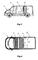
- a motor vehicle in the form of a dual usage van 1 having a body structure defining an interior space that is dividable by means of a moveable bulkhead 10 into a passenger area and a cargo area 'C'.
- a first row of seats 4 includes a driver's seat and is mounted in the van 1 so as to be permanently in an "in-use" condition.
- a stowable second row of seats 5 is located to the rear of the first row of seats 4.
- the second row of seats 5 in this case comprises of two seats 5a, 5b each of which is moveable between a stowed position and an "in-use" position.
- the van 1 has a side cargo door 3 on either or both sides to permit cargo to be loaded and unloaded from the side of the van 1 and to provide access to the second row seats 5 when they are in their "in-use" positions.
- the bulkhead 10 is reversibly transformable between a forward position located adjacent to but to the rear of the stowed second row seats 5 as shown in Figs.1 and 2 and a rear position located adjacent to but to the rear of the second row seats 5 in their "in-use" positions as shown in Figs. 3 and 4 .
- the plane 'p' indicates the position of the centre panel 12 would adopt if the bulkhead 10 were to be merely slid back.
- the moveable bulkhead 10 comprises of three panels 11, 12, 13 hingedly connected together so as to permit each panel 11, 12, 13 to rotate about a vertical axis relative to an adjacent panel 11, 12, 13 and latching means (not shown in Figs. 1 to 4 ) to selectively secure the panels 11, 12, 13 forming the bulkhead 10 in the van 1 either directly or via an adjoining panel so as to prevent rotation of the panels 11, 12, 13 and separate the cargo compartment 'C' of the van 1 from the passenger carrying compartment of the van 1.
- the bulkhead 10 is latchable by means of the latching means in the forward position and rear positions and is transformable between the two positions by the sequential un-latching, rotation and re-latching of the panels 11, 12, 13.
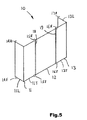
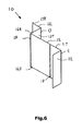
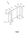
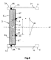
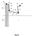
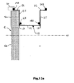
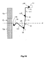
- FIGs 5 to 19 there is shown in diagrammatic form the transformation of the bulkhead 10 between the forward and rear positions including an intermediate position referred to hereinafter as a side locker position.
- the bulkhead 10 can be seen to comprise of first and second end panels 11 and 13 each of which extends forwardly when the bulkhead 10 is latched in the forward position in the van 1 as shown in Fig.5 and extends rearwardly when the bulkhead 10 is latched in the rear position in the van 1 as shown in Fig.8 .
- Each of the first and second end panels 11 and 13 is "L"-shaped having wing portions 11L, 13L that are arranged longitudinally with respect to the van 1 when the bulkhead 10 is latched in the van 1 in either of the forward and rear positions and body portions 11T, 13T that are arranged transversely with respect to the van 1 when the bulkhead 10 is latched in the van 1 in either of the forward and rear positions.
- the first end panel 11 is hingedly connected to a centre panel 12 by a number of hinges (not shown) so as to permit the first end panel 11 to pivot relative to the centre panel 12 about a vertical pivot axis 18 and the second end panel 13 is hingedly connected to the centre panel 12 by a number of hinges (not shown) so as to permit the second end panel 11 to pivot relative to the centre panel 12 about a vertical pivot axis 19.
- the bulkhead 10 includes a latching means including a number of latches 14, 15, 16 and 17 which comprise of an upper set of latches 14R, 15R, 16R and 17R which are arranged in use to be selectively engageable with a roof member of the van 1 and a lower set of latches 14F, 15F, 16F and 17F which are arranged in use to be selectively engageable with a floor structure of the van 1.
- a latching means including a number of latches 14, 15, 16 and 17 which comprise of an upper set of latches 14R, 15R, 16R and 17R which are arranged in use to be selectively engageable with a roof member of the van 1 and a lower set of latches 14F, 15F, 16F and 17F which are arranged in use to be selectively engageable with a floor structure of the van 1.
- the width of the centre panel 12 corresponds approximately to the distance by which the bulkhead 10 moves when it is transformed from its forward location to the rear location. That is to say, the distance between the latches 15R and 15F and the pivot axis 19 and the distance between the latches 16R and 16F and the pivot axis 18 are both equal to the distance between the securing positions of the bulkhead 10 in its forward and rear positions so that when the centre panel 12 is rotated though 90 degrees the bulkhead 10 can be re-latched to the vehicle 1 in the other position.
- the latches 14, 15, 16 and 17 are arranged in groups so that a single mechanism can be used to operate several of the latches 14, 15, 16 and 17.
- a first mechanism (not shown) is used to selectively simultaneously latch and unlatch the latches 14R, 15R, 14F and 15F as a first group and a second mechanism (not shown) is used to simultaneously latch and unlatch the latches 16R, 17R, 16F and 17F as a second group.
- This allows the first end panel 11 to be latched and unlatched by merely operating the first mechanism and similarly allows the second end panel 13 to be latched and unlatched by merely operating the second mechanism.
- the first step is to unlatch the latches 14R, 15R, 14F and 15F while maintaining the latches 16R, 17R, 16F and 17F latched.
- the first end panel 11 and the centre panel 12 can then be rotated relative to the second end panel 13 about the pivot axis 19 as shown in Fig.6
- the first end panel 11 can then be rotated relative to the centre panel 12 about the pivot axis 18 until it reaches its new rear position as shown in Fig.7 .
- the latches 14R, 15R, 14F and 15F are then re-latched so as to secure the first end panel 11 in the rear position.
- the latches 16R, 17R, 16F and 17F securing the second end panel 13 are then unlatched and the second end panel 13 along with the centre panel 12 are rotated about the pivot axis 18 until the second end panel 13 reaches its rear position as shown in Fig.8 and the latches 16R, 17R, 16F and 17F are then re-latched so as to secure the second end panel 13 in its rear position.
- the movement of the bulkhead 10 between its forward and rear positions is referred to as a transformation because the first end panel 11 is a left hand end panel when the bulkhead 10 is latched in the forward position and is a right hand end panel when the bulkhead 10 is latched in the rear position and the second end panel 13 is a left hand end panel when the bulkhead 10 is latched in the rear position and is a right hand end panel when the bulkhead 10 is latched in the forward position.
- the bulkhead 10 requires no tracks on the floor of the van the floor can remain flat and unobstructed thereby reducing the risk of an item of cargo fouling the tracks when being loaded or unloaded and the folding nature of the bulkhead 10 allows it to be operated simply with no risk of the operator becoming trapped in the cargo area 'C' of the van 1. In addition, because the bulkhead folds up, the bulkhead 10 can be more easily removed or installed in the van 1.
- the van 1 has a pair of front passenger doors, a pair of side hinged rear cargo doors, a side cargo door 3 in this case on each side of the van 1, a b-pillar 20 on each side of the van 1, each of the b-pillars 20 defining a front edge of an aperture 22 in a side of the van 1 and a c-pillar 21 on each side of the van 1 to the rear of the respective b-pillar 20 defining a rear edge of the aperture 22.
- Each of the apertures 22 defines a side cargo loading aperture that is closed off by a respective side cargo door 3 when the side cargo door 3 is in a closed position.
- the bulkhead 10 When the bulkhead 10 is located in the forward position, the bulkhead 10 is latchable by means of the latches 17R, 17F to the van 1 near to a right hand outer end at a position close to the b-pillar 20 on a right-hand side of the van 1 and the bulkhead 10 is latchable by means of the latches 14R, 14F to the van 1 near to a left hand outer end at a position close to the b-pillar 20 on a left-hand side of the van 1.
- This enables the bulkhead 10 to make use of the reinforcing structure used to connect the b-pillars 20 to the floor and roof structure of the van 1.
- the bulkhead 10 is U-shaped when it is latched in the forward position and the first and second end panels 11, 13 of the bulkhead 10, and in particular the wing portions 11L, 13L, extend longitudinally forwardly past the stowed second row seats 5 to positions where they are latched to the van 1 close to the b-pillars 20 as can be seen in Fig.9 .
- the bulkhead 10 forms a side-locker 50.
- the side locker 50 is located so as to be accessible via an adjacent side cargo door (not shown on Fig.13b ) and separates a cargo carrying area within the side-locker 50 from the passenger compartment of the van 1.
- the side locker 50 arrangement also permits one of the two seats 5a, 5b forming the second row seats 5 to be moved to its "in-use" position thereby permitting increased passenger carrying capacity while maintaining a positive separation from any articles carried in the side locker 50.
- each of the wing portions 11L, 13L of the first and second end panels 11, 13 is arranged longitudinally with respect to the van 1
- the body portions 11T, 13T of the end panels 11, 13 are arranged transversely with respect to the van 1
- the centre panel 12 is arranged longitudinally with respect to the van 1.
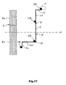
- the bulkhead 10 is transformed to the rear position as shown in Figs.14 to 17 by unlatching the second end panel 13 and rotating it about the pivot axis 19 and rotating the centre panel 12 about the pivot axis 18 so as to permit the second end panel 13 to move to a position where it can be re-latched to the van 1 in a corresponding position on an opposite side of the van 1 to the position where the first end panel 11 is latched as shown in Fig.18 .
- the second end panel 13 is then secured to the structure of the van 1 by re-latching the latches 16R, 16F, 17R and 17F.
- the bulkhead 10 when the bulkhead 10 is located in the rear position, the bulkhead 10 is latched to the van 1 near to a left hand outer end by the upper and lower latches 17R and 17F at a position close to the c-pillar 21 on a left-hand side of the van 1 and the bulkhead 10 is latched to the van 1 near to a right hand outer end by the upper and lower latches 14R and 14F at a position close to the c-pillar 21 on a right-hand side of the van 1.
- the volume 'V' is the volume gained by transforming the bulkhead 10 compared to a simple sliding of the bulkhead 10. That is to say the line 10' represents the position of the centre panel 12 and the body portions of the end panels 11, 13 if the bulkhead 10 was simply to be slid back from its forward position.
- a moveable bulkhead 110 for a motor vehicle such as the van 1 previously described which has a pair of front passenger doors (not shown), a pair of side hinged rear cargo doors (not shown), a side cargo door on each one side of the van 1 (not shown on the left hand side), a pair of b-pillars 20, one on each side of the van 1, each of the b-pillars 20 defining a front edge of an aperture 22 in a side of the van 1 and a pair of c-pillars 21, one on each side of the van 1 to the rear of the respective b-pillar 20 defining a rear edge of the aperture 22.
- Each of the apertures 22 defines a cargo loading aperture that is closed off by a respective side cargo door when the side cargo door is in a closed position.
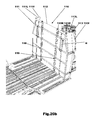
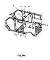
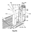
- the van 1 and the bulkhead 110 are much as described before and the moveable bulkhead 110 comprises of a first end panel 111 (having as before transverse and longitudinal portions 111T and 111L) which extends forwardly when the bulkhead 110 is latched in the forward position in the van 1 and extends rearwardly when the bulkhead 110 is latched in the rear position, a second end panel 113 (having as before transverse and longitudinal portions 113T and 113L) which extends forwardly when the bulkhead 110 is latched in a forward position in the van 1 and extends rearwardly when the bulkhead 110 is latched in the rear position and a centre panel 112 which is hingedly connected at one end to the first end panel 111 and is hingedly connected at an opposite end to the second end panel 113.
- the only significant difference between the bulkhead shown in Figs.20a to 22f and that shown and described in Figs.5 to 19 is the shape of the end panels 111 and 113 which are not simple oblongs but taper in towards their upper ends so as to conform to the interior shape of the van 1 and have flanges 111f and 113f which are used to mate with seals located on the van 1 or carry seals so as to mate with the body structure of the van 1.
- the width of the centre panel 112 is as before substantially the same as the distance between the forward and rear positions so as to allow the bulkhead 110 to be transformed and re-secured.
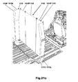
- the bulkhead 110 In figs.20a and 20b the bulkhead 110 is shown in its forward position and in Fig.21a and 21c the bulkhead 110 is shown in its rear position. In Fig.21b the bulkhead 110 is shown in its side locker position.
- the method by which the desired bulkhead transformation distance is achieved is by varying the width of the centre panel 112. This is because the width of the centre panel 112 corresponds approximately to the distance by which the bulkhead 110 moves when it is transformed from its forward location to the rear location. That is to say, the distance between the hinge axes 118 and 119 on either side of the centre panel 112 is substantially equal to the distance between the securing positions of the bulkhead 110 in its forward and rear positions, so that when the centre panel 112 is rotated though 90 degrees the bulkhead 110 can be re-latched to the vehicle 1 in the other position. It will be appreciated that there is a minor adjustment to this correlation as a result of the plan-view offsets between the hinge axis 118 and 119 and the adjacent latch pins.
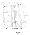
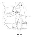
- first end panel 111 and in particular a latching mechanism used to selectively latch the first end panel 111 to the van 1.
- the second end panel 113 is not shown but the centre panel 112 is shown hingedly connected to the first end panel 111 for rotation about a vertical axis 118. It will be appreciated that in practice the latching mechanism may be concealed from view by an outer skin of the first end panel 111.
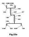
- the locking mechanism comprises of first and second upper latches 115R and 123R which are provided to secure an upper edge of the first end panel 111 to part of a roof structure of the van 1 and first and second lower latches 115F and 123F which are provided to secure a lower edge of the first end panel 111 to part of a floor structure of the van 1.
- All of the latches 115R, 123R, 115F and 123F are moved simultaneously by a single actuating handle "H” pivotally connected to part of the structure of the panel 111.
- the handle “H” is connected to an upper end of a master control link 138 such that rotation of the handle “H” in an upward direction will cause the master control link 138 to be raised and rotation of the handle “H” in a downward direction will cause the master control link 138 to be lowered.
- the master control link or rod 138 is driveably connected to a transfer lever 130.
- the transfer lever 130 is connected at one end to an upper actuator rod 137 slidingly supported at a number of positions 136 by the support structure of the end panel 111.
- An upper end of the upper actuator rod 137 is connected to an upper transfer rod 133 which is used to connect the first and second upper latches 115R and 123R to the master lever 130.
- the first and second upper latches 115R and 123R are slidingly supported in upper ends of two support tubes 132, 135.
- the opposite end of the transfer lever 130 is connected to the master control rod 138 which forms a lower actuator rod that is slidingly supported at a number of locations 131 by part of the structure of the panel 111.
- a lower end of the lower actuator rod 138 is connected to a lower transfer rod 134 which is used to connect the first and second lower latches 115F and 123F to the transfer rod 130.
- the first and second lower latches 115F and 123F are respectively slidingly supported in lower ends of the two support tubes 132, 135.
- a similar latching mechanism is used to selectively secure the second end panel 113.
- the flange 139 is provided to contact the floor structure 140 of the van 1 as the latch 123F is moved towards its fully latched position (as shown). This causes the first end panel 111 to be lifted away from the floor 140 as the latch 123R is moved to its fully latched position.
- a gap "G" of approximately 5 to 10 mm therefore is present between a lower edge of the end panel 111 and the floor 140 whenever the latch 123F is in its fully latched position.
- a similar arrangement is used for all of the latches used to latch or secure the bulkhead 110 to the van 1 so that when ever these latches are fully latched the corresponding panel is raised away from the floor 140 thereby allowing the bulkhead 110 to be more easily transformed than would be the case if the bulkhead 110 rested upon the floor 140.
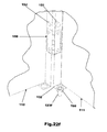
- FIG.22f A first alternative to the use of flanges 139 is shown in Fig.22f .
- Each of the latches is provided with a shoulder that acts on the floor and lifts the bulkhead 110 in the form of a nut 159 threadingly engaged with each rod 123F forming a latch so as to form a shoulder on the latch 123F.
- the latches could engage with depressions formed in the floor so that the latches act against the depressions and lift the bulkhead 110 clear of the floor.
- a hinge 150 is also shown on Fig.22f hingedly connecting the outer panel 111 to the centre panel 112 so as to form part of a pivotal connection therebetween. It will be appreciated that several such hinges 150 will be used to pivotally connect two panels together.
- the bulkhead 10 comprises of first and second end panels 11 and 13 each of which extends forwardly when the bulkhead 10 is latched in the forward position in the van 1 as shown in Fig.23 and extends rearwardly when the bulkhead 10 is latched in the rear position in the van 1.
- the bulkhead 10 includes a latching means including a number of latches 14, 15, 16, 17, 23, 24 which comprise of an upper set of latches 14R, 15R, 16R, 17R, 23R and 24R which are arranged in use to be selectively engageable with a roof member of the van 1 and a lower set of latches 14F, 15F, 16F, 17F, 23F and 24F which are arranged in use to be selectively engageable with a floor structure of the van 1.
- a latching means including a number of latches 14, 15, 16, 17, 23, 24 which comprise of an upper set of latches 14R, 15R, 16R, 17R, 23R and 24R which are arranged in use to be selectively engageable with a roof member of the van 1 and a lower set of latches 14F, 15F, 16F, 17F, 23F and 24F which are arranged in use to be selectively engageable with a floor structure of the van 1.
- a primary difference between the bulkhead shown in Fig.5 and the bulkhead shown in Fig.23 is that the bulkhead shown in Fig.5 has end panels that are of a fixed "L" shape whereas the bulkhead shown in Fig.23 has a first end panel 11 having a wing portion 11L hingedly connected to a body portion 11T for rotation about a vertical axis 25 and a second end panel 13 having a wing portion 13L hingedly connected to a body portion 13T for rotation about a vertical axis 26.
- One advantage of this arrangement is that the bulkhead 10 can be folded into a smaller package if it needs to be removed from the van 1.
- a bulkhead 10 which is the same as that shown in Fig.5 with the exception that the centre panel is formed as first and second centre panels 12a, 12b that are hingedly connected together for rotation about a pivot axis 27 and that three locks 28a, 28b and 28c are used to prevent rotation of the first and second centre panels 12a, 12b relative to one another during normal use.
- the locks 28a, 28b and 28c can be released when it is required to fold up the bulkhead 10 during installation or removal from the van 1.
- upper latches 214R, 215R, 216R and 217R are used to secure the bulkhead 210 to a roof structure of the van 1 and lower latches 214F, 215F, 216F and 217F are used to secure the bulkhead 210 to the floor structure of the van 1.
- a bulkhead which can be moved without the use of sliding elements.
- the moveable bulkhead consists of 3 vertical bulkhead portions which are joined by hinges, allowing the portions to be temporary de-latched to swivel about their hinge axes like doors.
- the panels and hinge axes are designed such that the unlatched panels can swing into the exact latching position for the translated bulkhead position. Once latched there, the other portions can be unlatched and similarly swung into the designated position and re-latched.
- the bulkhead can be easily installed as an after market feature as it does not rely on sliding rails incorporated to the body structure. Instead only two additional roof bows need to be bolted to the body inner structure and 2 floor cross members bolted to the floor to provide locations for the latches. The bulkhead panels can then simply be lifted in between a roof bow and a floor member and latched. The bulkhead is therefore always removable and/or stowable without the need for tools etc.
- this solution would require hinges which permit a certain amount of vertical movement and a lever mechanism on one hinge for each end panel which enables the end panel to be lifted with respect to the centre panel.
- the centre panel itself will be a few millimetres shorter then the end panels to ensure that the centre panel will always be suspended above the floor (to allow free rotation) by means of either or both of the two lever mechanisms which lift the end panels being set to the position where the end panel is dropped. This is to say the mechanism which lifts or drops an end panel with respect to the centre panel oppositely drops or lifts the centre panel with respect to the end panels.
Landscapes
- Engineering & Computer Science (AREA)
- Transportation (AREA)
- Mechanical Engineering (AREA)
- Health & Medical Sciences (AREA)
- Public Health (AREA)
- Body Structure For Vehicles (AREA)
Priority Applications (1)
| Application Number | Priority Date | Filing Date | Title |
|---|---|---|---|
| US13/037,402 US8474894B2 (en) | 2007-11-27 | 2011-03-01 | Movable bulkhead system to increase load capacity of a vehicle |
Applications Claiming Priority (1)
| Application Number | Priority Date | Filing Date | Title |
|---|---|---|---|
| GB0723201A GB2455089A (en) | 2007-11-27 | 2007-11-27 | Moveable bulkhead for a vehicle |
Publications (3)
| Publication Number | Publication Date |
|---|---|
| EP2065252A2 true EP2065252A2 (fr) | 2009-06-03 |
| EP2065252A3 EP2065252A3 (fr) | 2011-08-31 |
| EP2065252B1 EP2065252B1 (fr) | 2013-05-29 |
Family
ID=38962190
Family Applications (1)
| Application Number | Title | Priority Date | Filing Date |
|---|---|---|---|
| EP08170162.5A Not-in-force EP2065252B1 (fr) | 2007-11-27 | 2008-11-27 | Cloison déplaçable pour véhicule |
Country Status (4)
| Country | Link |
|---|---|
| US (2) | US8474894B2 (fr) |
| EP (1) | EP2065252B1 (fr) |
| CN (1) | CN101445074B (fr) |
| GB (1) | GB2455089A (fr) |
Cited By (4)
| Publication number | Priority date | Publication date | Assignee | Title |
|---|---|---|---|---|
| FR2977225A1 (fr) * | 2011-06-29 | 2013-01-04 | Peugeot Citroen Automobiles Sa | Cloisonnement d'un habitacle |
| FR2982812A1 (fr) * | 2011-11-18 | 2013-05-24 | Peugeot Citroen Automobiles Sa | Dispositif configurable pour la protection de sieges et de passagers dans un habitacle de vehicule |
| EP3597484A1 (fr) * | 2018-07-16 | 2020-01-22 | MAGNA STEYR Fahrzeugtechnik AG & Co KG | Véhicule de transport des personnes |
| FR3091508A1 (fr) * | 2019-01-09 | 2020-07-10 | Renault S.A.S | Dispositif de verrouillage d’une cloison mobile pivotante de véhicule. |
Families Citing this family (40)
| Publication number | Priority date | Publication date | Assignee | Title |
|---|---|---|---|---|
| DE102008052773B4 (de) * | 2008-10-22 | 2018-12-06 | Dr. Ing. H.C. F. Porsche Aktiengesellschaft | Baukastensystem und Herstellungsverfahren für Kraftfahrzeuge |
| JP2013180656A (ja) * | 2012-03-01 | 2013-09-12 | Kasai Kogyo Co Ltd | 車両のラゲージルーム構造 |
| US8608220B2 (en) * | 2012-03-30 | 2013-12-17 | Toyota Motor Engineering & Manufacturing North America, Inc. | Vehicle separating panel assembly with access to trunk release |
| USD696156S1 (en) * | 2012-05-04 | 2013-12-24 | Ford Motor Company | Vehicle |
| TWD159994S (zh) * | 2012-05-04 | 2014-04-21 | 福特環球科技有限公司 | 車輛 |
| USD701144S1 (en) * | 2012-08-27 | 2014-03-18 | Jonathan Mark Gould | Motor vehicle exterior |
| USD700106S1 (en) * | 2012-08-27 | 2014-02-25 | Jonathan Mark Gould | Motor vehicle exterior |
| US9381955B2 (en) * | 2013-06-24 | 2016-07-05 | David Ronsen | Apparatus and method to retrofit a refrigeration compartment with increased volume in a van |
| EP3086985B1 (fr) * | 2013-12-26 | 2018-04-11 | Tofas Turk Otomobil Fabrikasi Anonim Sirketi | Cloison à mécanisme coulissant |
| US10118559B2 (en) * | 2014-07-15 | 2018-11-06 | Abc Group Inc. | Interior cargo management divider system |
| USD780629S1 (en) * | 2014-09-12 | 2017-03-07 | Dur-A-Bus Coach Builders Ltd. | Bus |
| FR3035628B1 (fr) * | 2015-04-29 | 2017-05-26 | Faurecia Automotive Ind | Ensemble arriere de vehicule |
| US9688312B2 (en) | 2015-08-05 | 2017-06-27 | Honda Motor Co., Ltd. | Slidable pillar for adjusting an opening size into a vehicle and method thereof |
| US9926027B2 (en) | 2015-11-17 | 2018-03-27 | Dur-A-Bus Coach Builders Ltd. | Method for producing a bus |
| CN105539267A (zh) * | 2015-12-31 | 2016-05-04 | 苏州曹搞搞汽车厢体有限公司 | 一种用于快递业务的汽车分层厢体 |
| DE102016207773A1 (de) * | 2016-05-04 | 2017-11-09 | Volkswagen Aktiengesellschaft | Kraftfahrzeug mit einem eine Trennwand aufweisenden Laderaum |
| FR3051416B1 (fr) * | 2016-05-17 | 2019-06-21 | Renault S.A.S | Dispositif de separation entre un habitacle et un espace de chargement et vehicule equipe d'un tel dispositif |
| US10166928B2 (en) * | 2016-07-13 | 2019-01-01 | Ford Global Technologies, Llc | Storage compartment divider having partition with hinged telescoping sections |
| US20200256648A1 (en) * | 2016-11-18 | 2020-08-13 | Cronjé Venter | Protection apparatus for a vehicle |
| DE102017103691A1 (de) * | 2017-02-23 | 2018-08-23 | Dr. Ing. H.C. F. Porsche Aktiengesellschaft | Sicherungsvorrichtung für einen Innenraum eines Kraftfahrzeugs und Anordnung einer Sicherungsvorrichtung in einem Innenraum eines Kraftfahrzeugs |
| USD881753S1 (en) * | 2017-12-01 | 2020-04-21 | Nio Nextev Limited | Charging vehicle |
| US10513225B2 (en) * | 2018-02-13 | 2019-12-24 | GM Global Technology Operations LLC | Motor vehicle with height adjustable floor |
| US10604051B2 (en) * | 2018-05-30 | 2020-03-31 | GM Global Technology Operations LLC | Flipper panel system |
| GB2579837B (en) * | 2018-12-17 | 2021-05-12 | Ford Global Tech Llc | Movable bulkheads for a motor vehicle |
| USD948412S1 (en) | 2019-03-01 | 2022-04-12 | Werner Co. | Bulkhead for a vehicle |
| FR3094304B1 (fr) * | 2019-03-25 | 2021-03-05 | Renault Sas | Dispositif de séparation pour un véhicule automobile. |
| GB2592958B (en) * | 2020-03-11 | 2022-12-28 | Asg Group Ltd | Divider Arrangement |
| GB2592940B (en) * | 2020-03-11 | 2022-03-09 | Ford Global Tech Llc | Bulkhead for a vehicle |
| US20210331629A1 (en) * | 2020-04-22 | 2021-10-28 | Lyft, Inc. | Vehicle partition |
| CN113844403B (zh) * | 2020-06-28 | 2022-10-18 | 比亚迪股份有限公司 | 汽车隔离装置及汽车 |
| CA3124181C (fr) | 2020-07-08 | 2023-09-19 | Oshkosh Corporation | Assemblage de serrure de porte pour vehicule de livraison |
| USD962842S1 (en) * | 2020-10-08 | 2022-09-06 | Phantom Inc. | Vehicle partition |
| US11970139B2 (en) | 2020-10-23 | 2024-04-30 | Ford Global Technologies, Llc | System and method for modular vehicle storage |
| CN112758041B (zh) * | 2021-02-02 | 2022-05-06 | 常州市瑞悦车业有限公司 | 一种物流车厢用隔断保护装置 |
| US12263726B2 (en) * | 2021-03-02 | 2025-04-01 | Morgan Olson Corporation | Vehicle with sliding door |
| USD972483S1 (en) | 2022-04-04 | 2022-12-13 | Royce Sullivan | Modular bed system for vehicle cargo area |
| US11833955B1 (en) | 2022-07-09 | 2023-12-05 | Royce Sullivan | Modular bed and seat system for a rear cargo area of a vehicle |
| DE102022213998A1 (de) * | 2022-12-20 | 2024-06-20 | Stellantis Auto Sas | Wand mit Aufnahmemitteln für ein Nutzfahrzeug |
| WO2025251156A1 (fr) * | 2024-06-06 | 2025-12-11 | Remorques Cft Inc. | Remorque à zones conditionnées climatisées modulaires |
| US12304367B1 (en) | 2024-11-26 | 2025-05-20 | Royce John Sullivan | Modular van system |
Citations (1)
| Publication number | Priority date | Publication date | Assignee | Title |
|---|---|---|---|---|
| GB2384464A (en) | 2002-01-25 | 2003-07-30 | Primera Consultancy And Design | A movable bulkhead for a van |
Family Cites Families (45)
| Publication number | Priority date | Publication date | Assignee | Title |
|---|---|---|---|---|
| US3169781A (en) * | 1963-01-08 | 1965-02-16 | Samuel A Abruzzino | Safety net for vehicle occupants |
| US4345862A (en) * | 1980-11-17 | 1982-08-24 | Evans Products Company | Modular freight bracing bulkhead assembly |
| US4595227A (en) * | 1983-12-09 | 1986-06-17 | Setina John R | Motor vehicle partition apparatus with longitudinally offset sections |
| GB2213780B (en) * | 1987-07-16 | 1991-10-16 | Rees Operations Pty Ltd | Vehicle safety screen fixing means |
| US5058941A (en) * | 1990-01-31 | 1991-10-22 | Solomon Tony J | Vehicle interior barrier |
| FR2692861B1 (fr) * | 1992-06-30 | 1994-08-19 | Renault | Habitacle de véhicule automobile équipé de moyens de cloisonnement. |
| US5246261A (en) * | 1992-07-02 | 1993-09-21 | Mccormack Bill | Safety partition for motor vehicles |
| US5511842A (en) * | 1993-10-06 | 1996-04-30 | Dillon; John A. | Security vehicle system |
| US5584610A (en) * | 1993-12-23 | 1996-12-17 | Simpson; Garland E. | Bulkhead |
| US5597193A (en) * | 1994-05-31 | 1997-01-28 | Conner; Robert H. | Interlocking panel truck bed liners |
| AUPN453695A0 (en) * | 1995-08-02 | 1995-08-24 | Rees Operations Pty Ltd | Two position motor vehicle safety screen assembly |
| DE19962825A1 (de) * | 1999-12-23 | 2001-07-05 | Translock Ag Triesen | Abtrennung für geschlossene LKW-Aufbauten |
| KR20020039730A (ko) * | 2000-11-22 | 2002-05-30 | 이계안 | 차량의 화물적재공간 확장장치 |
| SE518271C2 (sv) * | 2001-02-01 | 2002-09-17 | Safe Load Internat Ab | Skiljevägg för temporär uppsättning samt balk för användning i och metod för tillverkande av skiljevägg för temporär uppsättning |
| US6676182B2 (en) * | 2001-04-19 | 2004-01-13 | Todd M. Fitts | Vehicle bed storage extender |
| US6502859B1 (en) * | 2001-06-18 | 2003-01-07 | Robert W. Svetlik | Automotive safety net system |
| US6669259B2 (en) * | 2001-11-09 | 2003-12-30 | Pro-Gard Industries, L.P. | Vehicle partition |
| EP1366953A1 (fr) * | 2002-05-30 | 2003-12-03 | Roje Holding B.V. | Conteneur avec cloisons de séparation détachables, en particulier pour moyens de transport |
| US6550849B1 (en) * | 2002-06-11 | 2003-04-22 | Ford Global Technologies, Inc. | Automotive vehicle with pass through cargo space |
| US6626478B1 (en) * | 2002-11-06 | 2003-09-30 | David J. Minton | Tailgate extender |
| WO2004054851A1 (fr) * | 2002-12-17 | 2004-07-01 | Rees Operations Pty Ltd | Montage ameliore pour une barriere de securite de vehicule automobile |
| DE10320527B3 (de) * | 2003-04-30 | 2004-12-09 | Bos Gmbh & Co. Kg | Trennvorrichtung für einen Fahrzeuginnenraum |
| US20050012357A1 (en) * | 2003-06-02 | 2005-01-20 | Richard Miller | Motor vehicle with a convertible rear compartment |
| US20060022493A1 (en) * | 2003-06-02 | 2006-02-02 | Miller Richard E | Motor vehicle with a convertible rear compartment |
| DE10330887A1 (de) * | 2003-07-09 | 2005-02-10 | Daimlerchrysler Ag | Laderaumsystem für Kraftfahrzeuge |
| EP1750970A4 (fr) * | 2004-05-24 | 2008-02-06 | Jr James D Wells | Cloisonnement de véhicule approprié pour collision |
| DE102004051015B4 (de) * | 2004-10-20 | 2010-01-21 | Daimler Ag | Kraftfahrzeug mit Trennwand |
| US7494177B2 (en) * | 2005-07-05 | 2009-02-24 | Aero Industries, Inc. | Bulkhead construction |
| US7318614B2 (en) * | 2005-08-23 | 2008-01-15 | L&P Property Management Company | Bulkhead assembly for vehicles |
| CN2858439Y (zh) * | 2005-12-02 | 2007-01-17 | 河南须河车辆有限公司 | 分体式手动半挂翼开启车厢 |
| TWM295606U (en) * | 2006-03-07 | 2006-08-11 | Chiou-Guei Wang | Auto dog fence capable of moving transversally |
| FR2898841B1 (fr) * | 2006-03-22 | 2009-03-06 | Peugeot Citroen Automobiles Sa | Vehicule automobile de type berline convertible pick-up. |
| US7731255B2 (en) * | 2007-04-10 | 2010-06-08 | Nissan Technical Center North America, Inc. | Interior vehicle cargo system |
| DE102007042371A1 (de) * | 2007-09-06 | 2009-03-12 | GM Global Technology Operations, Inc., Detroit | Höhenverstellvorrichtung für den Ladeboden eines Kraftfahrzeugs |
| US8177275B2 (en) * | 2007-11-05 | 2012-05-15 | Adrian Steel Company | Partition for vehicle cargo area |
| US7717484B2 (en) * | 2008-08-11 | 2010-05-18 | Darrin Parle | Vehicle partition |
| US7909379B2 (en) * | 2008-09-18 | 2011-03-22 | Global Ip Holdings, Llc | Kit and bulkhead assembly for cargo vehicles |
| US7806452B2 (en) * | 2009-02-09 | 2010-10-05 | Xtreme Metal Fab, Inc. | Adjustable security partition for a vehicle |
| JP5129175B2 (ja) * | 2009-02-13 | 2013-01-23 | 芦森工業株式会社 | カーゴネット装置 |
| JP5189006B2 (ja) * | 2009-02-13 | 2013-04-24 | 芦森工業株式会社 | カーゴネット装置 |
| US8136857B2 (en) * | 2009-12-30 | 2012-03-20 | Kawasaki Jukogyo Kabushiki Kaisha | Pick-up style utility vehicle with expandable cargo bed |
| JP2011207368A (ja) * | 2010-03-30 | 2011-10-20 | Mazda Motor Corp | 車両のトノカバー装置 |
| US8251426B2 (en) * | 2010-04-24 | 2012-08-28 | Ford Global Technologies, Llc | Collapsible seat construction for a vehicle |
| US8528957B2 (en) * | 2011-06-29 | 2013-09-10 | Ford Global Technologies, Llc | Cargo management system |
| US9056576B2 (en) * | 2012-12-28 | 2015-06-16 | Kawasaki Jukogyo Kabushiki Kaisha | Utility vehicle |
-
2007
- 2007-11-27 GB GB0723201A patent/GB2455089A/en not_active Withdrawn
-
2008
- 2008-11-26 CN CN200810177490.7A patent/CN101445074B/zh not_active Expired - Fee Related
- 2008-11-27 EP EP08170162.5A patent/EP2065252B1/fr not_active Not-in-force
-
2011
- 2011-03-01 US US13/037,402 patent/US8474894B2/en not_active Expired - Fee Related
-
2013
- 2013-06-28 US US13/931,174 patent/US9004567B2/en not_active Expired - Fee Related
Patent Citations (1)
| Publication number | Priority date | Publication date | Assignee | Title |
|---|---|---|---|---|
| GB2384464A (en) | 2002-01-25 | 2003-07-30 | Primera Consultancy And Design | A movable bulkhead for a van |
Cited By (5)
| Publication number | Priority date | Publication date | Assignee | Title |
|---|---|---|---|---|
| FR2977225A1 (fr) * | 2011-06-29 | 2013-01-04 | Peugeot Citroen Automobiles Sa | Cloisonnement d'un habitacle |
| FR2982812A1 (fr) * | 2011-11-18 | 2013-05-24 | Peugeot Citroen Automobiles Sa | Dispositif configurable pour la protection de sieges et de passagers dans un habitacle de vehicule |
| EP3597484A1 (fr) * | 2018-07-16 | 2020-01-22 | MAGNA STEYR Fahrzeugtechnik AG & Co KG | Véhicule de transport des personnes |
| US11851016B2 (en) | 2018-07-16 | 2023-12-26 | Magna Steyr Fahrzeugtechnik Gmbh & Co Kg | Passenger transport vehicle |
| FR3091508A1 (fr) * | 2019-01-09 | 2020-07-10 | Renault S.A.S | Dispositif de verrouillage d’une cloison mobile pivotante de véhicule. |
Also Published As
| Publication number | Publication date |
|---|---|
| EP2065252B1 (fr) | 2013-05-29 |
| GB2455089A (en) | 2009-06-03 |
| CN101445074A (zh) | 2009-06-03 |
| CN101445074B (zh) | 2013-03-20 |
| US8474894B2 (en) | 2013-07-02 |
| US20110148134A1 (en) | 2011-06-23 |
| US9004567B2 (en) | 2015-04-14 |
| GB0723201D0 (en) | 2008-01-09 |
| EP2065252A3 (fr) | 2011-08-31 |
| US20140028043A1 (en) | 2014-01-30 |
Similar Documents
| Publication | Publication Date | Title |
|---|---|---|
| EP2065252B1 (fr) | Cloison déplaçable pour véhicule | |
| US8020912B2 (en) | Rear closure assembly for a passenger vehicle | |
| US11433749B2 (en) | Vehicle convertible top systems | |
| US6752443B1 (en) | Load floor system | |
| US6955386B2 (en) | Underfloor stowage of a folding seat in a vehicle | |
| US6550849B1 (en) | Automotive vehicle with pass through cargo space | |
| US7121607B2 (en) | Truck bed extension | |
| US20160236724A1 (en) | Tailgate with load area extender for utility motor vehicle, and motor vehicle | |
| US8251426B2 (en) | Collapsible seat construction for a vehicle | |
| CN118665612A (zh) | 多功能货物最大化设备 | |
| EP2065250B1 (fr) | Siège escamotable | |
| US6131980A (en) | Foldable pickup bed for motor vehicles | |
| JP4157194B2 (ja) | バン型車両荷箱の扉構造 | |
| US20080122240A1 (en) | Tailgate for a Vehicle Comprising an Additional Load Carrier | |
| US12428075B2 (en) | Truck utility bed system | |
| US20050012357A1 (en) | Motor vehicle with a convertible rear compartment | |
| JP2000071830A (ja) | 自動車の車体構造 | |
| DE102018122990B4 (de) | Fahrzeugaufbau und Kühlfahrzeug mit einem solchen Fahrzeugaufbau | |
| US7681938B2 (en) | Convertible vehicle | |
| US20210053478A1 (en) | Vehicle interlocking tailgate utility bar | |
| JPS6299211A (ja) | ウイングボデイ形トラツク | |
| WO2025015405A1 (fr) | Système de hayon extensible pour véhicules | |
| CN208412881U (zh) | 压缩式后装垃圾车 | |
| JPH0621775Y2 (ja) | 車両のリヤボディ | |
| JP2022052618A (ja) | 車両用バックドア構造 |
Legal Events
| Date | Code | Title | Description |
|---|---|---|---|
| PUAI | Public reference made under article 153(3) epc to a published international application that has entered the european phase |
Free format text: ORIGINAL CODE: 0009012 |
|
| AK | Designated contracting states |
Kind code of ref document: A2 Designated state(s): AT BE BG CH CY CZ DE DK EE ES FI FR GB GR HR HU IE IS IT LI LT LU LV MC MT NL NO PL PT RO SE SI SK TR |
|
| AX | Request for extension of the european patent |
Extension state: AL BA MK RS |
|
| PUAL | Search report despatched |
Free format text: ORIGINAL CODE: 0009013 |
|
| AK | Designated contracting states |
Kind code of ref document: A3 Designated state(s): AT BE BG CH CY CZ DE DK EE ES FI FR GB GR HR HU IE IS IT LI LT LU LV MC MT NL NO PL PT RO SE SI SK TR |
|
| AX | Request for extension of the european patent |
Extension state: AL BA MK RS |
|
| RIC1 | Information provided on ipc code assigned before grant |
Ipc: B60P 3/42 20060101AFI20110722BHEP Ipc: B60P 7/14 20060101ALI20110722BHEP |
|
| 17P | Request for examination filed |
Effective date: 20120229 |
|
| AKX | Designation fees paid |
Designated state(s): DE FR GB TR |
|
| 17Q | First examination report despatched |
Effective date: 20120420 |
|
| GRAP | Despatch of communication of intention to grant a patent |
Free format text: ORIGINAL CODE: EPIDOSNIGR1 |
|
| GRAP | Despatch of communication of intention to grant a patent |
Free format text: ORIGINAL CODE: EPIDOSNIGR1 |
|
| GRAS | Grant fee paid |
Free format text: ORIGINAL CODE: EPIDOSNIGR3 |
|
| GRAA | (expected) grant |
Free format text: ORIGINAL CODE: 0009210 |
|
| AK | Designated contracting states |
Kind code of ref document: B1 Designated state(s): DE FR GB TR |
|
| REG | Reference to a national code |
Ref country code: GB Ref legal event code: FG4D |
|
| REG | Reference to a national code |
Ref country code: DE Ref legal event code: R096 Ref document number: 602008024966 Country of ref document: DE Effective date: 20130725 |
|
| PLBE | No opposition filed within time limit |
Free format text: ORIGINAL CODE: 0009261 |
|
| STAA | Information on the status of an ep patent application or granted ep patent |
Free format text: STATUS: NO OPPOSITION FILED WITHIN TIME LIMIT |
|
| 26N | No opposition filed |
Effective date: 20140303 |
|
| REG | Reference to a national code |
Ref country code: DE Ref legal event code: R097 Ref document number: 602008024966 Country of ref document: DE Effective date: 20140303 |
|
| REG | Reference to a national code |
Ref country code: FR Ref legal event code: PLFP Year of fee payment: 8 |
|
| REG | Reference to a national code |
Ref country code: FR Ref legal event code: PLFP Year of fee payment: 9 |
|
| REG | Reference to a national code |
Ref country code: FR Ref legal event code: PLFP Year of fee payment: 10 |
|
| REG | Reference to a national code |
Ref country code: FR Ref legal event code: PLFP Year of fee payment: 11 |
|
| PGFP | Annual fee paid to national office [announced via postgrant information from national office to epo] |
Ref country code: DE Payment date: 20191017 Year of fee payment: 12 |
|
| PGFP | Annual fee paid to national office [announced via postgrant information from national office to epo] |
Ref country code: FR Payment date: 20191029 Year of fee payment: 12 |
|
| PGFP | Annual fee paid to national office [announced via postgrant information from national office to epo] |
Ref country code: TR Payment date: 20191025 Year of fee payment: 12 |
|
| PGFP | Annual fee paid to national office [announced via postgrant information from national office to epo] |
Ref country code: GB Payment date: 20191029 Year of fee payment: 12 |
|
| REG | Reference to a national code |
Ref country code: DE Ref legal event code: R119 Ref document number: 602008024966 Country of ref document: DE |
|
| GBPC | Gb: european patent ceased through non-payment of renewal fee |
Effective date: 20201127 |
|
| PG25 | Lapsed in a contracting state [announced via postgrant information from national office to epo] |
Ref country code: FR Free format text: LAPSE BECAUSE OF NON-PAYMENT OF DUE FEES Effective date: 20201130 |
|
| PG25 | Lapsed in a contracting state [announced via postgrant information from national office to epo] |
Ref country code: DE Free format text: LAPSE BECAUSE OF NON-PAYMENT OF DUE FEES Effective date: 20210601 Ref country code: GB Free format text: LAPSE BECAUSE OF NON-PAYMENT OF DUE FEES Effective date: 20201127 |
|
| PG25 | Lapsed in a contracting state [announced via postgrant information from national office to epo] |
Ref country code: TR Free format text: LAPSE BECAUSE OF NON-PAYMENT OF DUE FEES Effective date: 20201127 |