EP2065300A1 - Plateforme de chargement pour un bateau - Google Patents
Plateforme de chargement pour un bateau Download PDFInfo
- Publication number
- EP2065300A1 EP2065300A1 EP08020364A EP08020364A EP2065300A1 EP 2065300 A1 EP2065300 A1 EP 2065300A1 EP 08020364 A EP08020364 A EP 08020364A EP 08020364 A EP08020364 A EP 08020364A EP 2065300 A1 EP2065300 A1 EP 2065300A1
- Authority
- EP
- European Patent Office
- Prior art keywords
- platform
- hoist
- connection head
- tailgate according
- lifting
- Prior art date
- Legal status (The legal status is an assumption and is not a legal conclusion. Google has not performed a legal analysis and makes no representation as to the accuracy of the status listed.)
- Withdrawn
Links
- XLYOFNOQVPJJNP-UHFFFAOYSA-N water Substances O XLYOFNOQVPJJNP-UHFFFAOYSA-N 0.000 title description 3
- 238000005096 rolling process Methods 0.000 claims description 3
- 238000006073 displacement reaction Methods 0.000 description 4
- 230000005540 biological transmission Effects 0.000 description 3
- 230000008878 coupling Effects 0.000 description 2
- 238000010168 coupling process Methods 0.000 description 2
- 238000005859 coupling reaction Methods 0.000 description 2
- 239000002184 metal Substances 0.000 description 2
- 206010041953 Staring Diseases 0.000 description 1
- 238000003287 bathing Methods 0.000 description 1
- 230000015572 biosynthetic process Effects 0.000 description 1
- 230000002596 correlated effect Effects 0.000 description 1
- 230000000875 corresponding effect Effects 0.000 description 1
- 238000007689 inspection Methods 0.000 description 1
- 239000000463 material Substances 0.000 description 1
Images


Classifications
-
- B—PERFORMING OPERATIONS; TRANSPORTING
- B63—SHIPS OR OTHER WATERBORNE VESSELS; RELATED EQUIPMENT
- B63B—SHIPS OR OTHER WATERBORNE VESSELS; EQUIPMENT FOR SHIPPING
- B63B27/00—Arrangement of ship-based loading or unloading equipment for cargo or passengers
- B63B27/14—Arrangement of ship-based loading or unloading equipment for cargo or passengers of ramps, gangways or outboard ladders ; Pilot lifts
-
- B—PERFORMING OPERATIONS; TRANSPORTING
- B63—SHIPS OR OTHER WATERBORNE VESSELS; RELATED EQUIPMENT
- B63B—SHIPS OR OTHER WATERBORNE VESSELS; EQUIPMENT FOR SHIPPING
- B63B29/00—Accommodation for crew or passengers not otherwise provided for
- B63B29/02—Cabins or other living spaces; Construction or arrangement thereof
- B63B2029/022—Bathing platforms
Definitions
- the invention relates to a tail lift for attachment to a watercraft, with a platform that can be raised and lowered and with a parallelogram hoist for the platform, wherein the hoist is attachable to the vessel via a Flanschkonsole.
- the term "tail lift” is intended to mean any generic device for lifting and lowering a platform on a watercraft. In this case, it would be particularly desirable for the platform to be liftable to a height level that corresponds, for example, to the deck level of the watercraft. Next, the platform in the raised state as possible be applied directly to the watercraft, so that no major gaps between the platform and watercraft are given. Also, it may be desirable if the walkable level the platform is substantially flush with the deck level of the vessel adapted.
- Tail lift at a watercraft is known from DE 196 25 155 A1
- Another tail lift at a watercraft is known from US 4,627,377 ; However, it does not include a parallelogram hoist for the platform, but the platform is held by a further cylinder drive at each lifting height in a horizontal position.
- the platform of a tail lift here in question can be lowerable in particular below the water surface. This allows the use of the tail lift or its platform as a bathing platform or it allows the launching or picking up a dinghy.
- a tail lift in which the platform can be lowered below the water surface, the structural problem arises in particular with motor boats that components of the tail lift collide with drive components of the watercraft.
- the components of the hoist in particular a two-sided parallelogrammförmige Hubtechniksanssen designed and in particular at the rear can be mounted so that they do not collide with drive components, this is more difficult in the extendable especially over the width of the vessel platform.
- the present invention has for its object to address this problem.
- a tail lift of the generic type which is characterized in that the platform is held linearly displaceable and so positively guided on a connection head of the hoist that it is forcibly moved in the horizontal direction in the course of the lifting and lowering movement of the hoist ,
- the platform in the raised state, the platform can at least be applied almost to the watercraft, and, on the other hand, it is possible to prevent collisions between the platform and the drive components of the watercraft when the platform is lowered.
- the tail lift is designed according to one embodiment, that the platform in the course of the lifting movement of the hoist with respect to the connection head in the direction of the Flange console, ie in the direction of the vessel, is moved. In the course of the lowering movement, the platform is moved in the opposite direction, that is to say in the aft direction, with reference to the connection head.
- a rigid, but at its ends pivotally hinged gear rod is provided between the flange and the platform platform, which moves the platform horizontally during the lifting movement of the hoist.
- the gear rod is preferably pivoted at its vehicle-side end directly to the flange of the tail lift.
- it is attached with its vehicle-side end to the vessel itself, with the former solution being given preference, since in this case all components of the tail lift can be optimally matched to one another.
- the other platform-side end of the transmission rod is connected to the platform via another rotary joint, preferably with an end region of the platform facing the watercraft.
- the gear rod is hinged in an advantageous manner in this end region of the platform from below, ie to an underside of the platform, pivotally.
- a sprocket segment is provided on the platform-side end of the hoist, which is in engagement with a linearly and horizontally extended teeth in the platform and in the course of Lifting and lowering movement of the hoist or the platform rolls rolling against the teeth in the platform.
- the platform is forcibly guided in the horizontal direction.
- the sprocket segment is non-rotatable with a support arm of the hoist and so in the course of lifting and lowering movement of the hoist or platform performs a relative movement to the connection head.
- the sprocket segment is rotatably formed with the lower arm of the hoist.
- the sprocket segment is circular segment and arranged with its center in the pivot point between the lower arm of the hoist and connection head.
- a pivotable with the hoist link plate is provided with a guide slot between the flange and the platform side platform, in which engages a cam pin of the platform, thereby in the course of the lifting and lowering movement of the hoist, the platform in horizontal direction is forcibly moved.
- This embodiment proves to be particularly advantageous, as the course of the guide slot of the cam plate is largely freely designable and thus the specific circumstances executable.
- the link plate could in turn be articulated directly on the vehicle. However, it proves to be advantageous if they work directly with the Flange console is pivotally connected.
- the link plate is hinged at one end to a vehicle-side pivot point of a support arm of the parallelogram hoist. Furthermore, it proves to be advantageous if the link plate at the other end, so on its side facing the platform, is articulated at a pivot point of the connection head to one of the support arms of the hoist.
- the tail lift according to the invention comprises a two-sided parallelogram-shaped hoisting arrangement, preferably with a torsion beam connecting both sides.
- the respective lower support arm of the parallelogram hoist extends beyond the pivot point of the connection head to the lower support arm and is provided at a distance from the pivot point of the Torsionschi.
- a coupling of two parallelogrammförmiger hoists can be realized with each other, without the risk that the provided for this purpose Torsionslic in the lowered state of the platform with drive components of the vessel collides.
- the coupling of the two-sided parallelogram hoists or Hoisting parts can be an arrangement with only one power drive for the Hoist can be designed.
- the tail lift can then be formed, for example, with only a single lifting cylinder in one of the Hubwerksmaschine.
- the drive for the hoist can be designed in any desired manner. It proves to be particularly advantageous if the hoist has at least one hydraulic cylinder (lifting cylinder), which is like the support arms of the respective parallelogram hoist advantageously hinged at one end pivotally on one end and attacks with its extendable piston rod at the other end on one of the support arms.
- a hydraulic drive and an electric motor actuator in the broadest sense or a mechanical or motor spindle drive can be used.
- the platform in a further embodiment of the tail lift according to the invention, it is proposed to form the platform with a vehicle-facing open-edged recess in order to be able to lower the platform via a Z drive of the watercraft.
- This proves to be advantageous in that the platform then has to be moved horizontally to a lesser extent.
- the open-edged recess When lowering the platform of the Z-drive is received by the open-edged recess.
- an appealing design in the rear region of the vessel is achieved overall.
- the recess with a plate-shaped component preferably substantially flush with the surface is closed when the platform is raised above the Z drive. It proves to be particularly advantageous if the plate-shaped component as a flap is hinged to the platform, which opens automatically when lowering the platform in particular. In such a case, the platform offers a surface continuous appearance when raised.
- the plate-shaped component in a ship's longitudinal direction and vertically extended cheeks are attached, which extend through the platform down and protect drive components of the vessel to the sides or shield when the platform is lowered.
- the platform forms a kind of slide, which is arranged horizontally displaceable relative to the hoist.
- the connection head for the platform at the platform-side end of the parallelogram hoist is designed as a slide carrier for the platform.
- connection head comprises a plate oriented vertically with its plane, which engages with an upper edge portion from below into a guide rail on the platform.
- This guide rail can advantageously comprise a metal profile strip, in particular an extruded profile strip, which has a downwardly open engagement slot for the connection head.
- This guide rail is suitably fastened against an underside of the platform, in particular bolted to the platform.
- sliding shoes are arranged, which are guided displaceably in the guide rail.
- the sliding shoes preferably comprise a plastic sliding material with tribologically suitable properties.
- the platform itself advantageously comprises a hollow chamber structure made of hollow profile strips, in particular extruded profile parts.
- this hollow chamber structure is overlapped by a plastic plate forming the upper visible side of the platform, wherein the plastic plate preferably extends downwards on the sides and thus conceals the horizontally displaceable arrangement of the platform on the lifting mechanism against inspection.
- FIG. 4 shows a perspective view of such generally designated by the reference numeral 2 tail lift.
- This comprises a two-sided parallelogram hoist 4, the two sides are connected to each other by means of a torsion tube 6.
- the parallelogram hoist 4 comprises an upper support arm 8 and a lower support arm 10, which form the horizontal parallel struts.
- the platform-side vertical parallelogram strut is formed by a connecting head 12 to be described in more detail, which then opens also to be described manner in FIG. 4 not shown platform 14 (see FIG. 6a ) holds.
- the respective hoist 4 is attached via a Flanschkonsole 16 to the watercraft 24.
- FIGS. 6a, 6b and 7 show further perspective views of the tail lift 2, wherein FIG. 6a the raised state and FIG. 6b the lowered state of the tail lift 2, and the platform 14 represents.
- FIG. 7 From the perspective view from below according to FIG. 7 It can be seen that the respective connection head 12 (left and right) of the two hoisting gear parts 4 engages in a arranged on the bottom 18 of the platform 14 guide rail 20.
- the platform 14 is namely forcibly guided in a manner to be described in more detail relative to the lifting mechanism 4 or the connection head 12 in the horizontal direction 22.
- the platform 14 assumes a certain horizontal position to the connection head 12 or to the hoist 4 of the tail lift 2 by a forced guidance arrangement to be described in more detail.
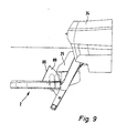
- FIGS. 8 and 9 the arrangement of the tail lift 2 at a rear end of a watercraft 24, in the raised or lowered state.
- the watercraft 24 is formed by way of example with a stern drive projecting aft Z-drive 25.
- the displaceable arrangement of the platform 14 on the two-sided connection head 12 of the lifting mechanism 4 illustrates the sectional view according to FIG. 5 , which initially also with reference to the FIGS. 4 and 7
- the platform 14 comprises a hollow chamber structure made of a plurality of light metal hollow profile strips 26, which is covered by an upper side of the platform 14 forming plastic plate 28.
- a guide rail 20 is fixed on both sides, by a screw connection.
- a pressure distribution piece 30 with an opening for a screw 31, which is inserted into the hollow chamber structure, is preferably provided in the abutting area of two adjoining hollow compartment profile strips 26.
- the screw 31 is then screwed into a threaded portion 32 in the guide rail 20 to fix them from below against the hollow chamber structure.
- the guide rail 20 comprises on its underside a slot-shaped opening 33 through which the connection head 12 engages with an upper edge portion 34.
- the respective connection head 12 comprises a plate 36 which is oriented vertically with its plane and which has a sliding shoe 38 on its upper edge section 34 on both sides. By means of these sliding shoes 38, the plate 36 in the guide rail 20 in the horizontal direction 22 is displaceable or in other words: the platform 14 can be against the plate 36, that is, compared to the connection head 12 of the hoist 4, in the horizontal direction 22 back and forth move.
- openings 40, 42 in the plate 36 and in the connection head 12 are shown. About these openings 40, 42, the plate 36 and the connection head 12 is pivotally connected in an upper hinge point 44 with the upper support arm 8 and in a lower hinge point 46 with the lower support arm 10.
- FIG. 1 illustrates a first embodiment of the positively driven linearly displaceable arrangement of the platform 14.
- a rigid Gear rod 48 is provided (see also FIG. 7 ).
- the gear rod 48 is pivotally mounted on the flange bracket 16 via a pivot 50 in a vertical plane.
- the other end of the transmission rod 48 is also pivotally connected to a vehicle-facing portion of the platform 14.
- the platform 14 on one of its underside 18 downwardly projecting tab 52.
- the tab 52 and the distance of the pivot point from the bottom and from the vehicle-facing edge of the platform 14 is formed such that the gear rod 48 does not collide with the lowering of the hoist 4 with the platform 14, but the platform in the in FIG. 1 Lower position shown below can be lowered.
- connection head 12th which is indeed pivoted as part of the parallelogram hoist (platform-side vertical parallelogram) itself.
- FIG. 2 illustrates a second embodiment of the tail lift according to the invention 2.
- a circular segment-shaped sprocket segment 66 is provided at the platform-side end of the hoist 4, which is in a linear and horizontal direction 22 arranged teeth 68 in the platform 14 into engagement.
- the sprocket segment 66 is arranged with its center point 70 in the example shown in the lower hinge point 46 between the connection head 12 and lower support arm 10.
- the sprocket segment 66 is, however, rotatably formed with the lower support arm 10 (but not with the connection head 12). In this way, a rolling movement of the sprocket segment 66 relative to the connection head 12 and thus with respect to the linear toothing 68 takes place at the platform 14, whereby the platform 14 when lowering the hoist 4 turn in aft direction 62 and when lifting in the forward direction 64 relative to the terminal head 12 is moved.
- FIG. 3 a third embodiment of the tail lift 2 according to the invention, wherein the positively driven horizontal displaceability of the platform 14 in dependence on the position of the lifting mechanism 4 is realized by a slotted guide between the platform 14 and a link plate 72.
- the link plate 72 is how out FIG. 3 can be seen, with its plane oriented vertically and pivotally mounted on the one hand on the vehicle-side upper hinge point 74 of the upper arm 8 to Flanschkonsole 16 and to a provided within the Flanschkonsole 16 vehicle side short strut of the parallelogram hoist 4.
- the link plate 72 is pivoted to the upper hinge point 44 between the connection head 12 and the upper support arm 8.
- the cam plate 72 could also be pivoted on a vehicle-side lower hinge point 76 and the platform-side lower hinge point 46 or at other points of the upper or lower support arm 8, 10.
- the guide plate 72 further has a guide slot 78, in which a guide pin 79 engages, which starts from a vehicle-facing edge region 56 of the platform 14 and extends in the direction of the pivot axes. In this way, the movement of the platform 14 is predetermined as a function of the lifting position of the hoist 4.
- the guide pin 79 passes through the guide slot 78, and the platform 14 is between the in FIG. 3 shown horizontal end positions with respect to the connection head 12, in turn when lowering the platform 14 in the aft direction 62 and when lifting the platform 14 in the forward direction 64 relative to the connection head 12th
- the lifting and lowering movement of the hoist 4 is carried out by a lifting cylinder 80 which is hinged at one end on the vehicle side in the case exemplified in the upper hinge point 74 of the upper arm 8 and the other end at a pivot point 82 on the lower arm 10 pivotally.
- FIGS. 6a, b the platform 14 has a vehicle-facing open-edged recess 84 in order to be lowered by means of a Z-drive 25 of the watercraft 24.
- this recess 84 is preferably closed flush by a plate-shaped component 86.
- the component 86 is articulated in the manner of a flap on the platform 14, which opens automatically when the platform is lowered over the Z-drive 25 or automatically closes again when the platform is raised again.
- the plate-shaped member 86 also has extended in a ship's longitudinal direction cheeks 88, which extend through the platform 14 down through and protect drive components of the vessel to the sides.
Landscapes
- Chemical & Material Sciences (AREA)
- Engineering & Computer Science (AREA)
- Combustion & Propulsion (AREA)
- Mechanical Engineering (AREA)
- Ocean & Marine Engineering (AREA)
- Body Structure For Vehicles (AREA)
- Closing And Opening Devices For Wings, And Checks For Wings (AREA)
Applications Claiming Priority (1)
| Application Number | Priority Date | Filing Date | Title |
|---|---|---|---|
| DE102007058831A DE102007058831B3 (de) | 2007-11-30 | 2007-11-30 | Hubladebühne für ein Wasserfahrzeug |
Publications (1)
| Publication Number | Publication Date |
|---|---|
| EP2065300A1 true EP2065300A1 (fr) | 2009-06-03 |
Family
ID=40340321
Family Applications (1)
| Application Number | Title | Priority Date | Filing Date |
|---|---|---|---|
| EP08020364A Withdrawn EP2065300A1 (fr) | 2007-11-30 | 2008-11-22 | Plateforme de chargement pour un bateau |
Country Status (2)
| Country | Link |
|---|---|
| EP (1) | EP2065300A1 (fr) |
| DE (1) | DE102007058831B3 (fr) |
Cited By (2)
| Publication number | Priority date | Publication date | Assignee | Title |
|---|---|---|---|---|
| EP2479104A1 (fr) * | 2011-01-20 | 2012-07-25 | H+B technics GmbH & Co. KG | Ascenseur à plateforme pour un bateau et bateau doté d'un système d'ascenseur à plateforme |
| CN105059483A (zh) * | 2015-08-17 | 2015-11-18 | 上海船舶研究设计院 | 一种救助艇限位辅助装置 |
Families Citing this family (6)
| Publication number | Priority date | Publication date | Assignee | Title |
|---|---|---|---|---|
| CH700562A2 (de) * | 2009-03-13 | 2010-09-15 | Peter A Mueller | Schlittenmittel in einem Führungsschienenmittel an einer Plattform für Wasserfahrzeuge. |
| DE202009007141U1 (de) | 2009-05-18 | 2009-08-20 | H + B Technics Gmbh + Co. Kg | Wasserfahrzeug mit einem Plattformlift |
| DE102009034204A1 (de) | 2009-07-16 | 2011-01-20 | Gerd Bär GmbH | Hubladebühne für den Anbau an ein Wasserfahrzeug, wie Sportboot, Motoryacht oder Segelyacht |
| CH702751A2 (de) * | 2010-02-16 | 2011-08-31 | Peter A Mueller | Absenkbarer Klapprahmen für Wasserfahrzeuge. |
| ITUB20159185A1 (it) * | 2015-12-14 | 2017-06-14 | Swissway Srl | Dispositivo di carico per un?imbarcazione perfezionato |
| ITUB20160814A1 (it) * | 2016-02-17 | 2017-08-17 | Swissway Srl | Dispositivo di carico per un’imbarcazione, provvista di cinematismo perfezionato per la trasmissione della rotazione del moto alla piattaforma |
Citations (4)
| Publication number | Priority date | Publication date | Assignee | Title |
|---|---|---|---|---|
| GB2372495A (en) * | 2001-01-12 | 2002-08-28 | Albert Michael Sanderson | Lifting apparatus for small water craft |
| FR2862275A1 (fr) * | 2003-11-17 | 2005-05-20 | Tenderlift Sarl | Dispositif escamotable de stockage et de mise a l'eau d'une annexe transformable en passerelle d'acces a un quai |
| WO2007087736A1 (fr) * | 2006-01-31 | 2007-08-09 | Mueller Peter A | Plateforme porteuse variable destinée à des véhicules marins |
| WO2009006753A1 (fr) * | 2007-07-12 | 2009-01-15 | Mueller Peter A | Commande forcée pour une plate-forme de bateau |
Family Cites Families (2)
| Publication number | Priority date | Publication date | Assignee | Title |
|---|---|---|---|---|
| FR2559732B1 (fr) * | 1984-02-17 | 1988-01-22 | Zoonens Alain | Dispositif bossoir pour bateaux notamment pour la mise a l'eau et le support d'un objet tel qu'une embarcation de sauvetage |
| DE19625155A1 (de) * | 1996-06-24 | 1998-01-08 | Klaus Friedrich | Hubeinrichtung |
-
2007
- 2007-11-30 DE DE102007058831A patent/DE102007058831B3/de not_active Expired - Fee Related
-
2008
- 2008-11-22 EP EP08020364A patent/EP2065300A1/fr not_active Withdrawn
Patent Citations (4)
| Publication number | Priority date | Publication date | Assignee | Title |
|---|---|---|---|---|
| GB2372495A (en) * | 2001-01-12 | 2002-08-28 | Albert Michael Sanderson | Lifting apparatus for small water craft |
| FR2862275A1 (fr) * | 2003-11-17 | 2005-05-20 | Tenderlift Sarl | Dispositif escamotable de stockage et de mise a l'eau d'une annexe transformable en passerelle d'acces a un quai |
| WO2007087736A1 (fr) * | 2006-01-31 | 2007-08-09 | Mueller Peter A | Plateforme porteuse variable destinée à des véhicules marins |
| WO2009006753A1 (fr) * | 2007-07-12 | 2009-01-15 | Mueller Peter A | Commande forcée pour une plate-forme de bateau |
Cited By (3)
| Publication number | Priority date | Publication date | Assignee | Title |
|---|---|---|---|---|
| EP2479104A1 (fr) * | 2011-01-20 | 2012-07-25 | H+B technics GmbH & Co. KG | Ascenseur à plateforme pour un bateau et bateau doté d'un système d'ascenseur à plateforme |
| CN105059483A (zh) * | 2015-08-17 | 2015-11-18 | 上海船舶研究设计院 | 一种救助艇限位辅助装置 |
| CN105059483B (zh) * | 2015-08-17 | 2017-05-10 | 上海船舶研究设计院 | 一种救助艇限位辅助装置 |
Also Published As
| Publication number | Publication date |
|---|---|
| DE102007058831B3 (de) | 2009-03-12 |
Similar Documents
| Publication | Publication Date | Title |
|---|---|---|
| DE102007058831B3 (de) | Hubladebühne für ein Wasserfahrzeug | |
| EP2616318B1 (fr) | Navire avec une passerelle d'embarquement | |
| EP0284836B1 (fr) | Véhicule de manutention pour manoeuvrer les avions au sol | |
| DE102011102110B4 (de) | Unterwagen für Raupenkran, Raupenkran und Verfahren zum Auf- und Abbau eines Raupenkrans | |
| EP2479104B1 (fr) | Ascenseur à plateforme pour un bateau et bateau doté d'un système d'ascenseur à plateforme | |
| EP0437286A2 (fr) | Véhicule tracteur pour la manutention des aéronefs | |
| EP0416539A1 (fr) | Dispositif d'accès pour véhicules automobiles, en particulier pour autobus | |
| AT513614B1 (de) | Leitersatz, insbesondere Feuerwehrleiter, sowie damit ausgestattetes Fahrzeug | |
| EP2275339A1 (fr) | Plate-forme de chargement pour l'installation sur un bateau, tel que bateau de sport nautique, yacht ou voilier | |
| EP1961691A2 (fr) | Appareil de transbordement | |
| DE10328540B4 (de) | Betätigungseinrichtung für eine an der Hinterkante des Tragflügels eines Flugzeugs angeordnete Ruderklappe | |
| DE3301746C2 (de) | Klapptritt für Schienenfahrzeuge | |
| AT513612B1 (de) | Leitersatz, insbesondere Feuerwehrleiter, sowie damit ausgestattetes Fahrzeug | |
| DE102007058908B3 (de) | Hubladebühne mit verstellbarem Hubwerk für ein Wasserfahrzeug | |
| EP0732256B1 (fr) | Dispositif pour basculer la cabine de conducteur d'un véhicule utilitaire | |
| EP1354759A1 (fr) | Plateau de chargement extensible | |
| DE3917284A1 (de) | Verstelleinrichtung an einem faltverdenk eines kraftfahrzeugs | |
| EP2248702B1 (fr) | Dispositif de levage | |
| DE3534257C2 (de) | Schwenkbar angeordnete Ablaufbahn für Freifallboote auf Schiffen | |
| EP3330170B1 (fr) | Système de stabilisation du roulis de bateaux et bateau | |
| DE69510141T2 (de) | An einem Fahrzeug anbringbare Lastenaufzugseinrichtung | |
| EP1743611B1 (fr) | Rampe extensible pour véhicules de transport en commun | |
| DE10203882B4 (de) | Mehrteiliges Schiebedach | |
| EP0253263A2 (fr) | Véhicule à fourgon avec mécanisme de levage | |
| DE2250562B2 (de) | Hebebuehne, insbesondere ladebordwand fuer kraftfahrzeuge |
Legal Events
| Date | Code | Title | Description |
|---|---|---|---|
| PUAI | Public reference made under article 153(3) epc to a published international application that has entered the european phase |
Free format text: ORIGINAL CODE: 0009012 |
|
| AK | Designated contracting states |
Kind code of ref document: A1 Designated state(s): AT BE BG CH CY CZ DE DK EE ES FI FR GB GR HR HU IE IS IT LI LT LU LV MC MT NL NO PL PT RO SE SI SK TR |
|
| AX | Request for extension of the european patent |
Extension state: AL BA MK RS |
|
| 17P | Request for examination filed |
Effective date: 20090905 |
|
| 17Q | First examination report despatched |
Effective date: 20091009 |
|
| AKX | Designation fees paid |
Designated state(s): AT BE BG CH CY CZ DE DK EE ES FI FR GB GR HR HU IE IS IT LI LT LU LV MC MT NL NO PL PT RO SE SI SK TR |
|
| STAA | Information on the status of an ep patent application or granted ep patent |
Free format text: STATUS: THE APPLICATION IS DEEMED TO BE WITHDRAWN |
|
| 18D | Application deemed to be withdrawn |
Effective date: 20110601 |