EP2065310A1 - Behälter für Kraftfahrzeugersatzteile - Google Patents
Behälter für Kraftfahrzeugersatzteile Download PDFInfo
- Publication number
- EP2065310A1 EP2065310A1 EP08105046A EP08105046A EP2065310A1 EP 2065310 A1 EP2065310 A1 EP 2065310A1 EP 08105046 A EP08105046 A EP 08105046A EP 08105046 A EP08105046 A EP 08105046A EP 2065310 A1 EP2065310 A1 EP 2065310A1
- Authority
- EP
- European Patent Office
- Prior art keywords
- base
- stacking
- axis
- articulation
- container according
- Prior art date
- Legal status (The legal status is an assumption and is not a legal conclusion. Google has not performed a legal analysis and makes no representation as to the accuracy of the status listed.)
- Withdrawn
Links
- 230000008093 supporting effect Effects 0.000 claims abstract description 11
- 238000003860 storage Methods 0.000 claims description 13
- 230000000295 complement effect Effects 0.000 claims description 8
- 241000422252 Cales Species 0.000 description 9
- 239000000463 material Substances 0.000 description 5
- 230000006835 compression Effects 0.000 description 3
- 238000007906 compression Methods 0.000 description 3
- 239000002184 metal Substances 0.000 description 3
- 229910052751 metal Inorganic materials 0.000 description 3
- 230000006378 damage Effects 0.000 description 2
- 230000000670 limiting effect Effects 0.000 description 2
- 238000009527 percussion Methods 0.000 description 2
- 125000006850 spacer group Chemical group 0.000 description 2
- 239000004743 Polypropylene Substances 0.000 description 1
- 230000000903 blocking effect Effects 0.000 description 1
- 238000006243 chemical reaction Methods 0.000 description 1
- 230000009850 completed effect Effects 0.000 description 1
- 238000006073 displacement reaction Methods 0.000 description 1
- 238000000605 extraction Methods 0.000 description 1
- 238000011049 filling Methods 0.000 description 1
- 239000006260 foam Substances 0.000 description 1
- 238000003780 insertion Methods 0.000 description 1
- 230000037431 insertion Effects 0.000 description 1
- 238000005304 joining Methods 0.000 description 1
- 238000012423 maintenance Methods 0.000 description 1
- 238000004519 manufacturing process Methods 0.000 description 1
- -1 polypropylene Polymers 0.000 description 1
- 229920001155 polypropylene Polymers 0.000 description 1
- 230000002829 reductive effect Effects 0.000 description 1
- 230000003578 releasing effect Effects 0.000 description 1
- 230000000630 rising effect Effects 0.000 description 1
- 230000011664 signaling Effects 0.000 description 1
Images


Classifications
-
- B—PERFORMING OPERATIONS; TRANSPORTING
- B65—CONVEYING; PACKING; STORING; HANDLING THIN OR FILAMENTARY MATERIAL
- B65D—CONTAINERS FOR STORAGE OR TRANSPORT OF ARTICLES OR MATERIALS, e.g. BAGS, BARRELS, BOTTLES, BOXES, CANS, CARTONS, CRATES, DRUMS, JARS, TANKS, HOPPERS, FORWARDING CONTAINERS; ACCESSORIES, CLOSURES, OR FITTINGS THEREFOR; PACKAGING ELEMENTS; PACKAGES
- B65D85/00—Containers, packaging elements or packages, specially adapted for particular articles or materials
- B65D85/68—Containers, packaging elements or packages, specially adapted for particular articles or materials for machines, engines or vehicles in assembled or dismantled form
-
- B—PERFORMING OPERATIONS; TRANSPORTING
- B65—CONVEYING; PACKING; STORING; HANDLING THIN OR FILAMENTARY MATERIAL
- B65D—CONTAINERS FOR STORAGE OR TRANSPORT OF ARTICLES OR MATERIALS, e.g. BAGS, BARRELS, BOTTLES, BOXES, CANS, CARTONS, CRATES, DRUMS, JARS, TANKS, HOPPERS, FORWARDING CONTAINERS; ACCESSORIES, CLOSURES, OR FITTINGS THEREFOR; PACKAGING ELEMENTS; PACKAGES
- B65D2585/00—Containers, packaging elements or packages specially adapted for particular articles or materials
- B65D2585/68—Containers, packaging elements or packages specially adapted for particular articles or materials for machines, engines, or vehicles in assembled or dismantled form
- B65D2585/6802—Containers, packaging elements or packages specially adapted for particular articles or materials for machines, engines, or vehicles in assembled or dismantled form specific machines, engines or vehicles
- B65D2585/6875—Containers, packaging elements or packages specially adapted for particular articles or materials for machines, engines, or vehicles in assembled or dismantled form specific machines, engines or vehicles engines, motors, machines and vehicle parts
- B65D2585/6882—Containers, packaging elements or packages specially adapted for particular articles or materials for machines, engines, or vehicles in assembled or dismantled form specific machines, engines or vehicles engines, motors, machines and vehicle parts vehicle parts
Definitions
- the invention relates to a container for storing and transporting a set of automobile spare parts, which comprises a base provided with means for supporting said spare parts in a prescribed arrangement.
- bumpers are most often manufactured and painted at a subcontractor, and then transported in trucks, to the factory assembly and manufacturing of motor vehicles.
- Such devices or containers adapted to the storage and transport of bumpers have already been proposed in the state of the art.
- they comprise a metal base, elongated rectangular general shape, which can be moved by means of a forklift, and later on the platform of a truck.
- This base is provided with supports, for example in the form of metal hoops on which are mounted parts wedging painted bumpers.
- the base is also equipped with a central grating, longitudinal, that the operator borrows to implement one by one the bumpers on the hoops.
- the invention aims to obtain a container of spare parts, which meets these requirements, while being ergonomic and to reduce storage and maintenance costs.
- An object of the invention is a container according to claim 1.
- the invention is described below for a container specifically intended for transporting bumpers in a vertical position.
- the spare parts can be any other, for example motor covers.
- the container 1 is formed of a metal base 10, which, seen from above, affects the shape of an elongated rectangle.
- This base 10 is thick and includes parallel passages for the introduction of the forks of a forklift.
- the base 10 has at its upper face means 11 for supporting PC bumpers in a vertical position.
- these support means 11 comprise rods extending in a longitudinal direction of the base 10, for example being arranged symmetrically with respect to the longitudinal vertical plane of symmetry of the container.
- the support means 11 are arranged relative to the shape of the PC bumpers, so that each PC bumper can fit on the means 11 in its storage arrangement shown in the figures, that is to say the substantially vertical position of the bumpers when the base 10 is horizontal.
- the container 1, 1a is stackable on another container 1, 1b, as shown in FIGS. Figures 16 and 17 .
- the container 1 comprises stacking means comprising, in the embodiment shown in the figures, two longitudinal elements 21, 22 articulated on the two longitudinal outer sides 12, 13 right and left of the base 10.
- the stacking means 21, 22 comprise, at their end remote from the base 10, one or more parts 23 intended to receive another container 1 in the stacking position of the containers.
- Each element 21, 22 comprises for example two uprights 24, 25 interconnected and rotatably articulated on the base 10. The articulations of the uprights 24, 25 are for example provided at the four corners of the base 10.
- the elements 21, 22 are held upward to define a first height H1 above the base 10 and a first width L1 between them, to define with the base 10 a storage space of the PC spare parts.
- the end portions 23 are then directed upwards to receive the base 10 of another container 1b above.
- the first position is also called the storage position.
- the elements 21, 22 are for example at 90 ° relative to the plane of the base 10, that is to say in a vertical position.
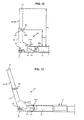
- At least one of the elements 21, 22, and in the embodiment shown, the two elements 21, 22 are adapted to be spaced from the base 10 outwardly from the first stacking position to arrive in a deployment position represented in the figure 2 .
- the first width L1 and the first height H1 may be only slightly greater than the dimensions of the PC spare parts, which makes it possible to save space in the container in the stacking position filled with PC spare parts, as shown in FIG. figure 5 .
- the elements 21, 22 delimit a second width L2 larger than the first width L1, to allow to introduce the PC spare parts on the base 10 through the top, the front and / or the rear of the base 10, without risk of hitting the container, so as not to damage the PC spare parts.
- the end portions 23 of the element 21, 22 are above the base 10 in the second deployment position.
- the end portions 23 of the element 21, 22 and / or the element 21, 22 are at a second height H2 non-zero above the base 10.
- the second position of the element 21, 22 is inclined outwards with respect to the vertical and is inclined above the plane of the horizontal taken on the base 10.
- the angle ⁇ of inclination of the element 21, 22 in the second deployment position in relation to the vertical or the first position has a non-zero fixed value, less than or equal to 45 ° and for example less than or equal to 30 ° and / or greater than or equal to 5 °. In the exemplary embodiment shown in figures 10 , 11 and 13 , this angle ⁇ has a value greater than or equal to 10 ° and less than or equal to 20 °.
- shims are provided to be arranged between the bumpers stored on the base 10.
- the insertion of the PC spare parts into the storage space of the container in this deployment position is performed as follows.
- the first bumper PC1 is placed on the support means 11 of the base 10.
- a fixed shim 39 can be provided on the base 10 to position the first bumper PC1 towards the bottom of the container. without it exceeding the storage space. It is for example provided two shims 39 fixed right and left.
- a shim 31 against the front of the spare part PC1.
- Means are provided for fixing the shims 31, 39 to each other.
- these means consist in that the rear face 32 of a wedge 31b has rearward projecting portions, formed for example by one or more projecting rods 33, which pass through corresponding holes of the PC spare part. come against another block 31a pressed against the rear of the same PC part by its front face 34.
- the projections 33 of the front spacer 31b pass through the spare part PC and are wedged in corresponding hollow parts 35 of the other rear shim 31a, so that the two shims 31 are fixed to each other at the front and rear of the PC part.
- the faces 32 and 34 are for example of complementary shape of the front and rear faces of the PC spare parts in the area where they must be mounted.
- the shims 31, 39 make it possible to protect the PC spare parts, and to prevent the parts from colliding during the handling and transport of the container.
- the wedges 31, 39 are made of a material that makes it possible to absorb or mitigate shocks, so as not to damage the PC parts and to keep them in their storage arrangement, in which the parts are spaced apart from one another as well as shown in the figure 5 .
- the mounting area of the wedges 31 is for example located on a stamped area of the spare part PC, formed for example by the mounting zone of a signaling light such as a flashing light or a night light in the case of a bumper.
- This stamped area has a recess on the front face of the PC bumper, against which comes a protrusion 37 of the face 32 of the front spacer 31 for the positioning of the wedge, the pins 33 protruding for example from this projection 37.
- PC spare part has a protrusion at the rear of the zone, against which comes the hollow 36 of the face 34 of the other rear shim 31 for the positioning of the wedge, this hollow 36 containing for example the recesses 35 for receiving the protruding pins 33.
- the shims 31 are for example provided on each front left and right side of the bumper PC 1.
- FIG. figure 2 there is a second PC2 bumper against the shim 31, 31a shown in FIG. figure 2 .
- the first shim 31a shown in FIG. figure 2 is immobilized on the fixed shim 39 back through the first bumper PC1.
- it is then fixed through the second bumper PC2 on the first wedge 31a of the figure 2 , a similar wedge 31b to immobilize it against the second bumper PC2.
- the wedge 31a is interposed between the bumpers PC 1 and PC2.
- a last hold before 31n is affixed against it, being fixed firstly to the previous hold 31n-1 and secondly to the base 10 by any means suitable, for example by a jamb or other.
- the container filled with PC parts can then be transported according to the figure 5 to stack several 1a, 1b and filled.
- the container 1b above has support means 15, located under its base 10 or in another appropriate part of the container, to bear against the bearing points 23 of the elements 21, 22 of the container 1a from below in position stacking.
- means 40 such as for example a rack 40 for supporting the removable shims 31 when they are not in use. against the bumpers, to store them in the empty position of the container.
- This rack 40 comprises for example one or more longitudinal rods 41, 42 connecting the two uprights 24, 25 of this element 21, 22.
- the wedges 31 are at least partially made of a compressible material, such as for example a foam, which can be made of expanded polypropylene to absorb shocks when placed between or against PC parts.
- the removable wedges 31 comprise one or more recesses 38, 39 in this compressible material for wedging the wedges on the rack 40 by placing the recesses 38, 39 against the rods 41, 42, the recesses 38, 39 having a corresponding shape. to these, the compression of the recesses 38, 39 by the rods 41, 42 ensuring the removable attachment of the wedges 31 on the rack 40.
- the elements 21, 22 are able to occupy, when there are no PC spare parts on the base 10, a third position folded against the base 10 with the shims stored on the element 21 and / or 22 folded .
- the element 21, 22 and the base 10 are for example arranged such that in this third folded position, the wedges 31 are wedged between the rack 40 and a part of the base 10, such as for example one of the means 11 of support.
- means 50 for locking and unlocking the element 21 and / or 22 relative to the base 10 are provided to allow the displacement of said element between the one and the other of the first stacking position, the second position deployed and the third folded position, as well as to block this element in the first stacking position and / or in the second position deployed outwardly.
- these locking means 50 comprise a connecting rod 51 connecting the base 10 and a gusset 52 or auxiliary piece 52, articulated in rotation on the same axis 53 as the amount 24, 25.
- the rod 51 is actuated by a handle 51a provided on it, to disengage the rod 51 relative to a corresponding portion 54 of the base 10 and push the amount 24 , or another part of the element 21, 22, outwards in the direction of the thick arrow shown in FIG. figure 10 , which causes the gusset 52 also to the outside.
- the latching portion 54 of the base 10 is for example formed by a male portion, formed for example by a finger 54, inserted into a slot 55 of the rod 51, forming a female latching portion.
- the female part 55 of the link 51 comprises at least two stop-points 55a, 55b side by side to insert and block the male part 54, respectively in the first stacking position and in the second deployed position.
- the male and female snap parts could be reversed on the rod 51 and on the base 10.
- the auxiliary stacking part 52 has in its auxiliary stacking position a height H3 above the base 10, which is less than the first height H1 had the support points 23 in the stacking position.
- the auxiliary parts 52 serve, in the folded position of the elements 21, 22, to stack empty containers 1, thus having a reduced overall height, the third height H3 being greater than the fourth height H4 occupied by the elements 21, 22 and their uprights 24, 25 when they are in the folded position towards the base 10.
- the PC spare parts are connected to each other by the shims and make a unitary assembly, which makes it impossible to move between PC parts.
- the shims disposed on the element 21, 22 serve as dampers and are trapped in the collapsed container, which prevents accidental losses of shims.
- Means 60 are provided between the upright 24, 25 and its associated auxiliary upright 52 to disengage in rotation the auxiliary stacking pillow 52 relative to the element 21, 22.
- the auxiliary stacking unit 52 is able to be locked in the auxiliary stacking position shown in figure 17 when the element 21, 22 passes from the first stacking position to the third folded position.
- the auxiliary post 52 is for example substantially 90 ° with respect to the plane of the base 10.
- the auxiliary stacking pillar 52 comprises an end portion 52a remote from its axis 53 of rotation on the base.
- the end portion 52a serves to support another container 1b above the third height H3 in the third folded position of the member 21, 22.
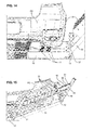
- the articulated element 21, 22 comprises a hinge portion 152, comprising for example a gusset connected in the first and second positions to the uprights 24, 25, the portion 152 being mounted by a hinge axis 153 in rotation on a corresponding portion 156 of support of the axis 153 on the base 10.
- the hinge portion 152 comprises or is integral with a first lower portion 157 of support located at a distance from the hinge axis 153.
- the lower support portion 157 is supported in the first position P1 on a first portion 158 of the base 10 located at a distance from the hinge axis 153.
- the lower support portion 157 is located below the level of the axis 153.
- the lower portion 157 is located, for example, in an offset manner towards the inside of the base 10, that is to say to the right for a element 21, 22 left to the figure 18 , relative to the axis 153.
- the lower portion 157 comprises for example a lower surface 157a of the gusset 152, or the inner and lower tip 157b of the gusset 152.
- the lower surface 157a of the gusset is for example flat.
- the flat lower surface 157a of the gusset is for example horizontal to be entirely supported on the portion 158 also horizontal for a surface contact, for example over the entire surface 157a.
- the bottom surface 157a of the gusset is connected in the direction of the axis 153 to a surface 159 obliquely and then to another surface, for example flat 160.
- the surfaces 159 and 160 are located above the longitudinal side 12, 13 associated with the element 21, 22, so as not to touch it in the first and second positions P1, P2, or when switching between them, these sides 12, 13 being formed for example under the element 21, 22 by a section parallel to the surfaces 159 and 160.
- the support portion 157 of the element 21, 22 is at a distance from the portion 158 of the base.
- the locking and unlocking means 50 may be omitted.
- the means 60 for joining and uncoupling described above can be provided.
- said articulated element 21, 22 is supported by a second outer support portion 26 located above the hinge axis 153 against a second outer portion 16 of the base 10 located at a distance from the hinge axis 153 above it.
- the second outer support portion 26 of the element 21, 22 is for example formed by the back of the portion 152 or gusset, located outside with respect to the axis 153.
- the second outer portion 16 of the base 10 is for example formed by an outer wall 16 of the base 10, connected on the side 12, 13. figure 18 , the second outer portion 16 of the base 10 is formed by the upper edge 16b of an outer vertical wall of the base 16, this upper edge 16b being for example at the same height as the upper inner plane 10b of the base 10.
- the articulated element 21, 22 comprises a hinge portion 152, comprising for example a gusset connected in the first and second positions to the uprights 24, 25, the portion 152 being mounted by a hinge axis 153 in rotation on a corresponding portion 156 of support of the axis 153 on the base 10.
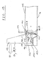
- the lever 170 for locking and unlocking in the first position P1, the lever 170 itself being hinged in rotation by another axis 171 on the hinge portion 152.
- This other axis 171 is remote from the first axis of articulation 153, but for example parallel thereto.
- the lever 171 comprises a portion 172 of abutment against a complementary abutment member 173 provided on the base 10, in order to lock the element 21, 22 in the first position P1 when the portion 172 is snapped against the body 173.
- the stop 172 of the lever 170 is under the member 173 in the detent position PE in the first position P1
- the axis 171 of the lever is carried by a lower portion 152b of the portion 152, the lower portion 152b being located under the axis 153 and being shifted inwardly of the base 10 relative thereto, which prevents the lower portion 152b of the element 21, 22 from rising, maintains the element 21, 22 in the first position P1 and prevents it from rotating from the first position P1 outwards and towards the second deployment position in the direction of the thick arrow A shown.
- Means are provided for disengaging the lever 170 to move it from its detent position PE where the portion 172 abuts against the member 173 at a disengaging position PDE for tilting the element 21, 22 of the first position P1 at the second outward deployment position P2, where the abutment portion 172 is disengaged and remote from the member 173.
- Means 175 for prestressing the lever 170 in the direction from the disengaging PDE position to the latching position, corresponding to the clockwise direction at the figure 19 are provided. They comprise for example a spring 175 bearing on the one hand on the axis 171 and on the other hand a point 176 of the lever remote from the axis 171. When the lever 170 is released, the spring 175 brings it back into position snap.
- a grip handle 174 is provided on a part of the lever remote from the axis 171, for example at its free end to rotate the lever 170 in its disengaged position PDE.
- the abutment member 173 comprises, for example, an open-hole plate or notch plate facing the pin of the lever 170, bearing the abutment portion 172 and connecting the handle 174 to the axis 171.
- the member 173 is, for example, welded on the base 10 at a level less than or equal to its upper inner plane 10b, the handle 174 protruding above and adjacent to this plane 10b to be accesible to the user.
- This portion 172 abutment is for example formed by a first nut 172 screwed on a corresponding thread provided around the spindle 170.
- a play catching means for example formed by a second locknut 172b screwed to the pin 170 under the first nut 172 is for example provided to be able to adjust the position by length of the nut 172 between the handle 174 and the axis 171, in order to be able to adjust the latching position in the first position P1 and prevent or reduce the play of the element 21, 22 in this first position P1.
Landscapes
- Engineering & Computer Science (AREA)
- Mechanical Engineering (AREA)
- Packaging Of Machine Parts And Wound Products (AREA)
- Stackable Containers (AREA)
Applications Claiming Priority (1)
| Application Number | Priority Date | Filing Date | Title |
|---|---|---|---|
| FR0708402A FR2924415A1 (fr) | 2007-11-30 | 2007-11-30 | Conteneur de pieces detachees d'automobiles |
Publications (1)
| Publication Number | Publication Date |
|---|---|
| EP2065310A1 true EP2065310A1 (de) | 2009-06-03 |
Family
ID=39575660
Family Applications (1)
| Application Number | Title | Priority Date | Filing Date |
|---|---|---|---|
| EP08105046A Withdrawn EP2065310A1 (de) | 2007-11-30 | 2008-08-14 | Behälter für Kraftfahrzeugersatzteile |
Country Status (3)
| Country | Link |
|---|---|
| EP (1) | EP2065310A1 (de) |
| DE (2) | DE08105046T1 (de) |
| FR (1) | FR2924415A1 (de) |
Cited By (3)
| Publication number | Priority date | Publication date | Assignee | Title |
|---|---|---|---|---|
| DE102009032656B3 (de) * | 2009-07-09 | 2011-03-17 | Montaplast Gmbh | Stapelgestelle |
| CN107879046A (zh) * | 2017-12-25 | 2018-04-06 | 武汉燎原模塑有限公司 | 一种能运载多种保险杠零件的运载小车 |
| CN108249011A (zh) * | 2018-01-15 | 2018-07-06 | 江南模塑科技股份有限公司 | 通用存储器具 |
Citations (5)
| Publication number | Priority date | Publication date | Assignee | Title |
|---|---|---|---|---|
| EP1052193A1 (de) * | 1999-05-06 | 2000-11-15 | Industrie Lissa Dal Pra' S.p.A. | Container zum Lagern und Transportieren von Motorrädern und ähnlichen Zweirädern |
| FR2832387A1 (fr) * | 2001-11-21 | 2003-05-23 | Europ De Conception De Contene | Dispositif pour le stockage et le transport d'elements allonges, tels que des pare-chocs |
| US20040168946A1 (en) * | 2003-01-27 | 2004-09-02 | Safelite Glass Corp. | Reusable windshield pallet |
| FR2860212A1 (fr) * | 2003-09-30 | 2005-04-01 | Europ De Conception De Contene | Dispositif pour le stockage et le transport d'elements allonges a pieces de soutien interchangeables |
| EP1801033A1 (de) * | 2005-12-23 | 2007-06-27 | Cabinet Lhermet La Bigne & Remy | Stoßfängerträger, -verkleidung und -verstärkung |
-
2007
- 2007-11-30 FR FR0708402A patent/FR2924415A1/fr not_active Withdrawn
-
2008
- 2008-08-14 DE DE2008105046 patent/DE08105046T1/de active Pending
- 2008-08-14 EP EP08105046A patent/EP2065310A1/de not_active Withdrawn
- 2008-08-14 DE DE200820017410 patent/DE202008017410U1/de not_active Expired - Lifetime
Patent Citations (5)
| Publication number | Priority date | Publication date | Assignee | Title |
|---|---|---|---|---|
| EP1052193A1 (de) * | 1999-05-06 | 2000-11-15 | Industrie Lissa Dal Pra' S.p.A. | Container zum Lagern und Transportieren von Motorrädern und ähnlichen Zweirädern |
| FR2832387A1 (fr) * | 2001-11-21 | 2003-05-23 | Europ De Conception De Contene | Dispositif pour le stockage et le transport d'elements allonges, tels que des pare-chocs |
| US20040168946A1 (en) * | 2003-01-27 | 2004-09-02 | Safelite Glass Corp. | Reusable windshield pallet |
| FR2860212A1 (fr) * | 2003-09-30 | 2005-04-01 | Europ De Conception De Contene | Dispositif pour le stockage et le transport d'elements allonges a pieces de soutien interchangeables |
| EP1801033A1 (de) * | 2005-12-23 | 2007-06-27 | Cabinet Lhermet La Bigne & Remy | Stoßfängerträger, -verkleidung und -verstärkung |
Cited By (5)
| Publication number | Priority date | Publication date | Assignee | Title |
|---|---|---|---|---|
| DE102009032656B3 (de) * | 2009-07-09 | 2011-03-17 | Montaplast Gmbh | Stapelgestelle |
| CN107879046A (zh) * | 2017-12-25 | 2018-04-06 | 武汉燎原模塑有限公司 | 一种能运载多种保险杠零件的运载小车 |
| CN107879046B (zh) * | 2017-12-25 | 2023-11-21 | 武汉燎原模塑有限公司 | 一种能运载多种保险杠零件的运载小车 |
| CN108249011A (zh) * | 2018-01-15 | 2018-07-06 | 江南模塑科技股份有限公司 | 通用存储器具 |
| CN108249011B (zh) * | 2018-01-15 | 2023-12-29 | 江南模塑科技股份有限公司 | 通用存储器具 |
Also Published As
| Publication number | Publication date |
|---|---|
| FR2924415A1 (fr) | 2009-06-05 |
| DE202008017410U1 (de) | 2009-09-10 |
| DE08105046T1 (de) | 2009-10-08 |
Similar Documents
| Publication | Publication Date | Title |
|---|---|---|
| EP0070800B1 (de) | Fracht-Container | |
| CA2263035A1 (fr) | Vehicule de deplacement pour enfant en bas age | |
| EP0141757A1 (de) | Fahrradträger zur Befestigung auf Trägerbrücken von Kraftfahrzeugen | |
| EP4056241B1 (de) | Ausrüstung zum praktizieren von basketball | |
| FR2767298A1 (fr) | Poussette ayant un ensemble de frein | |
| EP1045789B1 (de) | Lagerungs-und transporteinrichtung, insbesondere für motorräder | |
| EP2065310A1 (de) | Behälter für Kraftfahrzeugersatzteile | |
| FR2877635A1 (fr) | Dispositif antivol de maintien en stationnement d'un vehicule a deux roues | |
| EP4051534B1 (de) | Kraftfahrzeug ausgestattet mit aufbewahrungsboxen | |
| EP1201549B1 (de) | Zusammenklappbarer Palettenbehälter | |
| FR2936773A1 (fr) | Velo pliable a roulette de stabilisation | |
| EP2946994B1 (de) | Anhänger für zweirad-fahrzeug | |
| FR3051431A1 (fr) | Support destine a ranger un engin roulant | |
| FR2763909A1 (fr) | Dispositif pour le stockage et le transport de motocyclette | |
| EP0595744B1 (de) | Zerlegbare und stapelbare Palette, insbesondere für plattenförmige Produkte | |
| EP1696771B1 (de) | Vorrichtung zur anzeige einer reihe von objekten | |
| EP1038726B1 (de) | Vorrichtung zur Sicherung von Lasten | |
| EP4056242A1 (de) | Ausrüstung zum praktizieren von basketball | |
| FR2717445A1 (fr) | Dispositif de calage de bouteilles de gaz en vue de leur transport, notamment dans le coffre d'un véhicule automobile. | |
| EP1762279A1 (de) | Golfausrüstung mit Handwagen und Tasche | |
| BE1031613B1 (fr) | Cycle équipé d’une caisse de stockage pliable | |
| FR2713132A1 (fr) | Dispositif de support pour le tronçonnage de bois de chauffage disposé en tas. | |
| EP3882082A1 (de) | Fahrzeug mit verbessertem schwenkarm | |
| FR2889118A1 (fr) | Ensemble d'assise pour vehicule et vehicule comportant un tel ensemble d'assise | |
| FR2741309A1 (fr) | Porte-charges repliable pour vehicule automobile |
Legal Events
| Date | Code | Title | Description |
|---|---|---|---|
| PUAI | Public reference made under article 153(3) epc to a published international application that has entered the european phase |
Free format text: ORIGINAL CODE: 0009012 |
|
| AK | Designated contracting states |
Kind code of ref document: A1 Designated state(s): AT BE BG CH CY CZ DE DK EE ES FI FR GB GR HR HU IE IS IT LI LT LU LV MC MT NL NO PL PT RO SE SI SK TR |
|
| AX | Request for extension of the european patent |
Extension state: AL BA MK RS |
|
| DET | De: translation of patent claims | ||
| STAA | Information on the status of an ep patent application or granted ep patent |
Free format text: STATUS: THE APPLICATION IS DEEMED TO BE WITHDRAWN |
|
| 18D | Application deemed to be withdrawn |
Effective date: 20091208 |