EP2065524B1 - Ablaufvorrichtung - Google Patents
Ablaufvorrichtung Download PDFInfo
- Publication number
- EP2065524B1 EP2065524B1 EP08020387.0A EP08020387A EP2065524B1 EP 2065524 B1 EP2065524 B1 EP 2065524B1 EP 08020387 A EP08020387 A EP 08020387A EP 2065524 B1 EP2065524 B1 EP 2065524B1
- Authority
- EP
- European Patent Office
- Prior art keywords
- channel
- drainage
- panel
- drainage device
- drainage body
- Prior art date
- Legal status (The legal status is an assumption and is not a legal conclusion. Google has not performed a legal analysis and makes no representation as to the accuracy of the status listed.)
- Active
Links
Images

Classifications
-
- E—FIXED CONSTRUCTIONS
- E03—WATER SUPPLY; SEWERAGE
- E03F—SEWERS; CESSPOOLS
- E03F5/00—Sewerage structures
- E03F5/04—Gullies inlets, road sinks, floor drains with or without odour seals or sediment traps
- E03F5/0407—Floor drains for indoor use
- E03F5/0408—Floor drains for indoor use specially adapted for showers
-
- A—HUMAN NECESSITIES
- A47—FURNITURE; DOMESTIC ARTICLES OR APPLIANCES; COFFEE MILLS; SPICE MILLS; SUCTION CLEANERS IN GENERAL
- A47K—SANITARY EQUIPMENT; ACCESSORIES THEREFOR, e.g. TOILET ACCESSORIES
- A47K3/00—Baths; Showers; Appurtenances therefor
- A47K3/28—Showers or bathing douches
- A47K3/40—Pans or trays
- A47K3/405—Pans or trays flush with the surrounding floor, e.g. for easy access
-
- E—FIXED CONSTRUCTIONS
- E03—WATER SUPPLY; SEWERAGE
- E03F—SEWERS; CESSPOOLS
- E03F3/00—Sewer pipe-line systems
- E03F3/04—Pipes or fittings specially adapted to sewers
- E03F3/046—Open sewage channels
-
- E—FIXED CONSTRUCTIONS
- E03—WATER SUPPLY; SEWERAGE
- E03F—SEWERS; CESSPOOLS
- E03F5/00—Sewerage structures
- E03F5/04—Gullies inlets, road sinks, floor drains with or without odour seals or sediment traps
- E03F2005/0416—Gullies inlets, road sinks, floor drains with or without odour seals or sediment traps with an odour seal
Definitions
- the present invention relates to a drain device for a damp room, in particular for a shower, according to the preamble of claim 1.
- Such a drain device is used, for example, in barrier-free showers.
- the plate-shaped parts can serve as a support surface for tiles, for example, or they can themselves be part of the surface of the shower floor.
- the generally very cumbersome assembly proves to be a disadvantage of such drainage devices.
- a drain device of the type mentioned is known.
- a channel-shaped drain body is introduced into a plate-shaped part and preassembled to form a unit by gluing it to this part.
- the top sides of the plate-shaped part and the drain body are essentially flush.
- a drain device in which a channel-shaped drain body is foamed into a plate-shaped part.
- the top of the drain body projects slightly beyond that of the plate-shaped part, so that tiles applied to the plate-shaped part are flush with the drain body.
- a drain connection extends downward out of the plate-shaped part from the drain body.
- the problem on which the present invention is based is the creation of a drain device of the type mentioned at the beginning, which can be stored in a space-saving manner.
- the channel-shaped drain body in the installed position does not protrude downward beyond the plate-shaped part, so that the preassembled unit of the channel-shaped drain body and plate-shaped part can be easily stacked.
- the channel-shaped drain body and the at least partially plate-shaped part can be detachably or non-detachably connected to one another, in particular glued or screwed to one another. Furthermore, there is the possibility that the channel-shaped drain body and the at least partially plate-shaped part are welded to one another or clipped to one another or latched to one another or connected to one another by being pushed, for example into a dovetail guide.
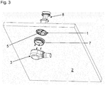
- the drain device essentially comprises a channel-shaped drain body 1, an at least partially plate-shaped part 2 and a drain pot 3.
- the channel-shaped drain body 1 consists, for example, of plastic and / or steel and, in the position of use, has an upper elongated inlet opening (not shown) through which waste water can enter the channel.
- a cover element (not shown) can be arranged in or on the channel. The inlet opening can extend between the channel and the cover element, in particular around the cover element.
- the at least partially plate-shaped part 2 can consist of mineral casting, for example. Other materials that can serve as a surface for a shower area are also conceivable here. For example, wood, preferably impregnated wood, could also be used.
- the at least partially plate-shaped part 2 can be a finished, in Installation position upper surface, so that it can form the surface of the shower area itself. This significantly simplifies assembly because after the installation of part 2, no further measures need to be taken in order to achieve an attractive surface for the shower area.
- the at least partially plate-shaped part 2 serves as a support surface for tiles or another floor covering.
- the channel-shaped drain body 1 and the at least partially plate-shaped part 2 are preassembled to form a unit. This can be implemented, for example, by gluing and / or screwing.
- the drain pan 3 can be preassembled in the floor of the damp room.
- the drain pot 3 has a drain connector which can be connected to a drain line.
- the embodiment shown is designed such that the channel-shaped drain body 1 can be arranged in the plate-shaped part 2.
- the underside of the drain body 1 in the preassembled state ends flush with the underside of the plate-shaped part 2 (see Fig. 3 ).
- the top of the drain body 1 in the preassembled state is flush with the top of the plate-shaped part 2. Due to the fact that the channel-shaped drain body 1 is arranged in the plate-shaped part 2 and in the installed position protrudes neither downward nor upward beyond the plate-shaped part 2, the preassembled unit can be easily stacked.
- a sealing insert 7 can be screwed onto the underside of the pre-assembled drain body 1, which is inserted into the drain pot 3 from above can be inserted.
- FIGS. 1 to 3 Another odor trap unit 8 is shown, which can be introduced into the channel-shaped drain body 1 from above.
- the drain body 1 furthermore has a lateral bevel 9 which corresponds to a bevel 10 of the plate-shaped part 2.
- the bevel 9 promotes the entry of waste water into the inlet opening 11.
- the bevel 9 continues the bevel 10 provided in the plate-shaped part 2, so that the drainage device has an attractive appearance.
Landscapes
- Health & Medical Sciences (AREA)
- Public Health (AREA)
- Life Sciences & Earth Sciences (AREA)
- Engineering & Computer Science (AREA)
- Hydrology & Water Resources (AREA)
- Water Supply & Treatment (AREA)
- Epidemiology (AREA)
- General Health & Medical Sciences (AREA)
- Sink And Installation For Waste Water (AREA)
- Residential Or Office Buildings (AREA)
- Bathtubs, Showers, And Their Attachments (AREA)
Description
- Die vorliegende Erfindung betrifft eine Ablaufvorrichtung für einen Feuchtraum, insbesondere für eine Dusche, gemäß dem Oberbegriff des Anspruchs 1.
- Eine derartige Ablaufvorrichtung findet beispielsweise bei barrierefreien Duschen Verwendung. Dabei können die plattenförmigen Teile beispielsweise als Auflagefläche für Fliesen dienen oder bereits selbst Teil der Oberfläche des Duschenbodens sein. Als nachteilig bei derartigen Ablaufvorrichtungen erweist sich die in der Regel sehr umständliche Montage.
- Aus der
EP 1 782 721 A2 ist eine Ablaufvorrichtung der eingangs genannten Art bekannt. Bei der darin beschriebenen Ablaufvorrichtung ist ein rinnenförmiger Ablaufkörper in ein plattenförmiges Teil eingebracht und durch Verkleben mit diesem Teil zu einer Einheit vormontiert. Dabei schließen die Oberseiten des plattenförmigen Teils und des Ablaufkörpers im Wesentlichen bündig ab. - Aus der
DE 10 2006 007 471 A1 ist eine Ablaufvorrichtung bekannt, bei der in ein plattenförmiges Teil ein rinnenförmiger Ablaufkörper eingeschäumt ist. Dabei überragt die Oberseite des Ablaufkörpers diejenige des plattenförmigen Teils etwas, so dass auf das plattenförmige Teil aufgebrachte Fliesen bündig mit dem Ablaufkörper abschließen. Weiterhin erstreckt sich von dem Ablaufkörper ein Ablaufstutzen aus dem plattenförmigen Teil nach unten heraus. - Das der vorliegenden Erfindung zugrunde liegende Problem ist die Schaffung einer Ablaufvorrichtung der eingangs genannten Art, die platzsparender zu lagern ist.
- Dies wird erfindungsgemäß durch eine Ablaufvorrichtung der eingangs genannten Art mit den kennzeichnenden Merkmalen des Anspruchs 1 erreicht. Die Unteransprüche betreffen bevorzugte Ausgestaltungen der Erfindung.
- Gemäß Anspruch 1 ist vorgesehen, dass der rinnenförmige Ablaufkörper in Einbaulage auch nicht nach unten über das plattenförmige Teil hinausragt, so dass sich die vormontierte Einheit aus rinnenförmigem Ablaufkörper und plattenförmigem Teil einfach stapeln lässt.
- Beispielsweise können dabei der rinnenförmige Ablaufkörper und das zumindest abschnittsweise plattenförmige Teil lösbar oder unlösbar miteinander verbunden sein, insbesondere miteinander verklebt oder verschraubt sein. Weiterhin besteht die Möglichkeit, dass der rinnenförmige Ablaufkörper und das zumindest abschnittsweise plattenförmige Teil miteinander verschweißt oder miteinander verklipst oder miteinander verrastet oder durch Einschieben, wie beispielsweise in eine Schwalbenschwanzführung, miteinander verbunden sind.
- Weitere Merkmale und Vorteile der vorliegenden Erfindung werden deutlich anhand der nachfolgenden Beschreibung bevorzugter Ausführungsbeispiele unter Bezugnahme auf die beiliegenden Abbildungen. Darin zeigen
- Fig. 1
- eine perspektivische Explosionsdarstellung einer erfindungsgemäßen Ablaufvorrichtung;
- Fig. 2
- einen Schnitt durch die erfindungsgemäße Ablaufvorrichtung im montierten Zustand;
- Fig. 3
- eine weitere perspektivische Explosionsdarstellung der erfindungsgemäßen Ablaufvorrichtung.
- Die Ablaufvorrichtung umfasst im wesentlichen einen rinnenförmigen Ablaufkörper 1, ein zumindest abschnittsweise plattenförmiges Teil 2 und einen Ablauftopf 3.
- Der rinnenförmige Ablaufkörper 1 besteht beispielsweise aus Kunststoff und/oder Stahl und weist in Gebrauchslage eine obere langgestreckte Einlauföffnung auf (nicht abgebildet), durch die Abwasser in die Rinne eintreten kann. Beispielsweise kann in oder auf der Rinne ein Abdeckelement (nicht abgebildet) angeordnet werden. Zwischen der Rinne und dem Abdeckelement kann sich die Einlauföffnung erstrecken, insbesondere um das Abdeckelement herum.
- Das zumindest abschnittsweise plattenförmige Teil 2 kann beispielsweise aus Mineralguss bestehen. Hier sind auch andere Materialien denkbar, die als Oberfläche für einen Duschbereich dienen können. Beispielsweise könnte auch Holz, vorzugsweise imprägniertes Holz Verwendung finden. Das zumindest abschnittsweise plattenförmige Teil 2 kann eine fertig bearbeitete, in Einbaulage obere, Oberfläche aufweisen, so dass es selbst die Oberfläche des Duschbereichs bilden kann. Dadurch wird die Montage deutlich vereinfacht, weil nach dem Einbau des Teils 2 keine weiteren Maßnahmen mehr ergriffen werden müssen, um eine ansprechende Oberfläche des Duschbereichs zu erzielen.
- Alternativ besteht auch die Möglichkeit, dass das zumindest abschnittsweise plattenförmige Teil 2 als Auflagefläche für Fliesen oder einen anderen Bodenbelag dient.
- Der rinnenförmige Ablaufkörper 1 und das zumindest abschnittsweise plattenförmige Teil 2 sind zu einer Einheit vormontiert. Dies kann beispielsweise durch Verkleben und/oder Verschrauben realisiert werden.
- Der Ablauftopf 3 kann im Boden des Feuchtraums vormontiert werden. Der Ablauftopf 3 weist einen Ablaufstutzen auf, der mit einer Ablaufleitung verbunden werden kann.
- Die abgebildete Ausführungsform ist so gestaltet, dass der rinnenförmige Ablaufkörper 1 in dem plattenförmigen Teil 2 angeordnet werden kann. Insbesondere schließt die Unterseite des Ablaufkörpers 1 im vormontierten Zustand bündig mit der Unterseite des plattenförmigen Teils 2 ab (siehe
Fig. 3 ). Weiterhin schließt auch die Oberseite des Ablaufkörpers 1 im vormontierten Zustand bündig mit der Oberseite des plattenförmigen Teils 2 ab. Aufgrund der Tatsache, dass der rinnenförmige Ablaufkörper 1 in dem plattenförmigen Teil 2 angeordnet ist und in Einbaulage weder nach unten noch nach oben über das plattenförmige Teil 2 hinausragt, kann die vormontierte Einheit einfach gestapelt werden. - An die Unterseite des vormontierten Ablaufkörpers 1 kann ein Dichteinsatz 7 angeschraubt werden, der in den Ablauftopf 3 von oben eingeschoben werden kann. Zusätzlich ist in den
Fig. 1 bis Fig. 3 noch eine Geruchsverschlusseinheit 8 abgebildet, die von oben in den rinnenförmigen Ablaufkörper 1 eingebracht werden kann. - Der Ablaufkörper 1 weist weiterhin eine seitliche Anschrägung 9 auf, die zu einer Anschrägung 10 des plattenförmigen Teils 2 korrespondiert. Durch die Anschrägung 9 wird einerseits das Eintreten des Abwassers in die Einlauföffnung 11 begünstigt. Andererseits setzt die Anschrägung 9 die in dem plattenförmigen Teil 2 vorgesehene Anschrägung 10 fort, so dass sich ein ansprechendes Äußeres der Ablaufvorrichtung ergibt.
Claims (10)
- Ablaufvorrichtung für einen Feuchtraum, insbesondere für eine Dusche, umfassend- einen rinnenförmigen Ablaufkörper (1) mit einer Einlauföffnung (11), in die Abwasser eintreten kann, wobei der Ablaufkörper (1) mindestens eine Auslassöffnung (5) aufweist, aus der das Abwasser austreten kann,- ein zumindest abschnittsweise plattenförmiges Teil (2), das Teil eines Bodens des Feuchtraums, insbesondere der Dusche, sein kann, wobei der rinnenförmige Ablaufkörper (1) und das zumindest abschnittsweise plattenförmige Teil (2) zu einer Einheit vormontiert sind, wobei der rinnenförmige Ablaufkörper (1) in dem plattenförmigen Teil (2) angeordnet ist, und wobei der rinnenförmige Ablaufkörper (1) in Einbaulage nicht nach oben über das plattenförmige Teil (2) hinausragt,dadurch gekennzeichnet, dass der rinnenförmige Ablaufkörper (1) in Einbaulage auch nicht nach unten über das plattenförmige Teil (2) hinausragt, so dass sich die vormontierte Einheit aus rinnenförmigem Ablaufkörper (1) und plattenförmigem Teil (2) einfach stapeln lässt.
- Ablaufvorrichtung nach Anspruch 1, dadurch gekennzeichnet, dass der rinnenförmige Ablaufkörper (1) und das zumindest abschnittsweise plattenförmige Teil (2) lösbar oder unlösbar miteinander verbunden sind.
- Ablaufvorrichtung nach Anspruch 2, dadurch gekennzeichnet, dass der rinnenförmige Ablaufkörper (1) und das zumindest abschnittsweise plattenförmige Teil (2) miteinander verklebt oder miteinander verschweißt sind.
- Ablaufvorrichtung nach Anspruch 2, dadurch gekennzeichnet, dass der rinnenförmige Ablaufkörper (1) und das zumindest abschnittsweise plattenförmige Teil (2) miteinander verschraubt oder miteinander verklipst oder miteinander verrastet oder durch Einschieben, wie beispielsweise in eine Schwalbenschwanzführung, miteinander verbunden sind.
- Ablaufvorrichtung nach einem der Ansprüche 1 bis 4, dadurch gekennzeichnet, dass der rinnenförmige Ablaufkörper (1) zumindest teilweise aus Kunststoff besteht.
- Ablaufvorrichtung nach einem der Ansprüche 1 bis 5, dadurch gekennzeichnet, dass der rinnenförmige Ablaufkörper (1) zumindest teilweise aus Metall, insbesondere Stahl, besteht.
- Ablaufvorrichtung nach einem der Ansprüche 1 bis 6, dadurch gekennzeichnet, dass das zumindest abschnittsweise plattenförmige Teil (2) eine bearbeitete, in Einbaulage obere, Oberfläche aufweist, die insbesondere gebrauchsfertig bearbeitet ist.
- Ablaufvorrichtung nach einem der Ansprüche 1 bis 7, dadurch gekennzeichnet, dass das zumindest abschnittsweise plattenförmige Teil (2) zumindest teilweise aus Mineralguss besteht.
- Ablaufvorrichtung nach einem der Ansprüche 1 bis 8, dadurch gekennzeichnet, dass die Ablaufvorrichtung einen Ablauftopf (3) aufweist, der in dem Boden des Feuchtraums vormontiert werden kann.
- Ablaufvorrichtung nach Anspruch 9, dadurch gekennzeichnet, dass die Ablaufvorrichtung einen Dichteinsatz (7) umfasst, der in Einbaulage von unten an dem vormontierten rinnenförmigen Ablaufkörper (1) angebracht, vorzugsweise angeschraubt, werden kann, wobei der Dichteinsatz (7) mit dem Ablauftopf (3) verbindbar ist.
Priority Applications (5)
| Application Number | Priority Date | Filing Date | Title |
|---|---|---|---|
| SI200832156T SI2065524T1 (sl) | 2007-11-30 | 2008-11-24 | Drenažna naprava |
| PL10002508T PL2196587T3 (pl) | 2007-11-30 | 2008-11-24 | Urządzenie odpływowe |
| DK10002508.9T DK2196587T3 (da) | 2007-11-30 | 2008-11-24 | Afløbsindretning |
| PL08020387T PL2065524T3 (pl) | 2007-11-30 | 2008-11-24 | Urządzenie odpływowe |
| EP10002508.9A EP2196587B1 (de) | 2007-11-30 | 2008-11-24 | Ablaufvorrichtung |
Applications Claiming Priority (2)
| Application Number | Priority Date | Filing Date | Title |
|---|---|---|---|
| DE102007058028 | 2007-11-30 | ||
| DE102008046671A DE102008046671A1 (de) | 2007-11-30 | 2008-09-10 | Ablaufvorrichtung |
Related Child Applications (1)
| Application Number | Title | Priority Date | Filing Date |
|---|---|---|---|
| EP10002508.9A Division-Into EP2196587B1 (de) | 2007-11-30 | 2008-11-24 | Ablaufvorrichtung |
Publications (3)
| Publication Number | Publication Date |
|---|---|
| EP2065524A2 EP2065524A2 (de) | 2009-06-03 |
| EP2065524A3 EP2065524A3 (de) | 2009-10-21 |
| EP2065524B1 true EP2065524B1 (de) | 2020-12-16 |
Family
ID=40586043
Family Applications (2)
| Application Number | Title | Priority Date | Filing Date |
|---|---|---|---|
| EP08020387.0A Active EP2065524B1 (de) | 2007-11-30 | 2008-11-24 | Ablaufvorrichtung |
| EP10002508.9A Not-in-force EP2196587B1 (de) | 2007-11-30 | 2008-11-24 | Ablaufvorrichtung |
Family Applications After (1)
| Application Number | Title | Priority Date | Filing Date |
|---|---|---|---|
| EP10002508.9A Not-in-force EP2196587B1 (de) | 2007-11-30 | 2008-11-24 | Ablaufvorrichtung |
Country Status (7)
| Country | Link |
|---|---|
| EP (2) | EP2065524B1 (de) |
| DE (1) | DE102008046671A1 (de) |
| DK (2) | DK2065524T3 (de) |
| ES (2) | ES2422711T3 (de) |
| PL (2) | PL2065524T3 (de) |
| PT (1) | PT2065524T (de) |
| SI (1) | SI2065524T1 (de) |
Families Citing this family (12)
| Publication number | Priority date | Publication date | Assignee | Title |
|---|---|---|---|---|
| BE1019528A5 (nl) * | 2010-10-05 | 2012-08-07 | Aquadraat Engineering Bvba | Dal en werkwijze voor het vervaardigen van een dal en hemelwaterafvoersysteem voorzien van zulke dal. |
| NL2005864C2 (nl) * | 2010-12-16 | 2012-06-19 | Easy Sanitairy Solutions Bv | Vlakke plaat goot. |
| DE102011000342A1 (de) * | 2011-01-26 | 2012-07-26 | Franz Kaldewei Gmbh & Co. Kg | Sanitäranordnung, insbesondere bodengleiche Dusche |
| EP2591709B1 (de) | 2011-11-10 | 2018-03-21 | poresta systems GmbH | Duschbodenelement und Einbauset für ein Duschbodenelement |
| DE102012110726A1 (de) | 2011-11-10 | 2013-05-16 | Poresta Systems Gmbh | Duschbodenelement und Einbauset für ein Duschbodenelement |
| DE202012100725U1 (de) | 2011-11-10 | 2013-02-14 | Poresta Systems Gmbh | Duschbodenelement und Einbauset für ein Duschbodenelement |
| EP2687136B1 (de) | 2012-07-20 | 2017-03-15 | Dallmer GmbH & Co. KG | Duschelement |
| DE102013105542A1 (de) | 2013-05-29 | 2014-12-04 | Wedi Gmbh | Wasserablaufvorrichtung für eine Dusche und Duschbodenelement |
| IL230110A0 (en) * | 2013-12-23 | 2014-03-31 | Huliot A C S Ltd | Kit for linear floor drainage |
| ES2555671B1 (es) * | 2014-07-04 | 2016-09-20 | Baroan Rioja, S.L. | Dispositivo de desagüe con orificio de entrada no circular |
| DE102016125311A1 (de) * | 2016-12-22 | 2018-06-28 | Wedi Gmbh | Wasserablauf für einen Duschboden mit einem universell einsetzbaren Anschlussadapter |
| WO2021262072A1 (en) * | 2020-06-26 | 2021-12-30 | Orbital Systems Ab | System for water quality measurement and a recirculation system comprising the system |
Family Cites Families (8)
| Publication number | Priority date | Publication date | Assignee | Title |
|---|---|---|---|---|
| AT327819B (de) * | 1974-11-19 | 1976-02-25 | Guggemos Horst | Sohlschale fur gerinne, insbesondere fur kanale |
| DE9103590U1 (de) * | 1991-03-23 | 1991-06-27 | Birco Baustoffwerk GmbH, 7570 Baden-Baden | Abflußrinne mit oberseitiger Abdeckung |
| GB0209755D0 (en) * | 2002-04-29 | 2002-06-05 | Alumasc Construction Products | Slot drain |
| FR2846348A1 (fr) * | 2002-10-28 | 2004-04-30 | Marc Gabriel Jean M Dombrowski | Procede et dispositif pour realiser une reservation etanche dans du beton et permettant de rendre etanches les conduits existants, utilisant un film plastique |
| GB2415455B (en) * | 2004-06-22 | 2009-03-25 | Quintin Anthony Murfin | Controlled filter strip |
| PL1782721T3 (pl) | 2005-11-02 | 2015-12-31 | Viega Tech Gmbh & Co Kg | Brodzik prysznicowy z rynną odpływową |
| DE102006007471B4 (de) | 2006-02-17 | 2012-09-06 | Basika Entwässerungstechnik GmbH & Co. KG | Duschbodenelement und Trägerelement dafür, sowie Duschbodenunterbau aus einem Duschbodenelement und einem Trägerelement für bodengleiche Duschen |
| FR2928156B1 (fr) * | 2008-02-29 | 2014-05-23 | Farhooman Davoudi | Ensemble bonde/siphon d'evacuation compose de plusieurs gardes d'eau |
-
2008
- 2008-09-10 DE DE102008046671A patent/DE102008046671A1/de not_active Ceased
- 2008-11-24 PL PL08020387T patent/PL2065524T3/pl unknown
- 2008-11-24 EP EP08020387.0A patent/EP2065524B1/de active Active
- 2008-11-24 EP EP10002508.9A patent/EP2196587B1/de not_active Not-in-force
- 2008-11-24 PT PT80203870T patent/PT2065524T/pt unknown
- 2008-11-24 DK DK08020387.0T patent/DK2065524T3/da active
- 2008-11-24 PL PL10002508T patent/PL2196587T3/pl unknown
- 2008-11-24 ES ES10002508T patent/ES2422711T3/es active Active
- 2008-11-24 DK DK10002508.9T patent/DK2196587T3/da active
- 2008-11-24 ES ES08020387T patent/ES2854849T3/es active Active
- 2008-11-24 SI SI200832156T patent/SI2065524T1/sl unknown
Non-Patent Citations (1)
| Title |
|---|
| None * |
Also Published As
| Publication number | Publication date |
|---|---|
| EP2196587A3 (de) | 2010-08-25 |
| DE102008046671A1 (de) | 2009-06-04 |
| DK2196587T3 (da) | 2013-07-29 |
| ES2854849T3 (es) | 2021-09-23 |
| SI2065524T1 (sl) | 2021-07-30 |
| DK2065524T3 (da) | 2021-03-08 |
| EP2065524A2 (de) | 2009-06-03 |
| ES2422711T3 (es) | 2013-09-13 |
| PL2196587T3 (pl) | 2013-09-30 |
| PL2065524T3 (pl) | 2021-06-28 |
| EP2065524A3 (de) | 2009-10-21 |
| EP2196587B1 (de) | 2013-04-24 |
| EP2196587A2 (de) | 2010-06-16 |
| PT2065524T (pt) | 2021-03-04 |
Similar Documents
| Publication | Publication Date | Title |
|---|---|---|
| EP2065524B1 (de) | Ablaufvorrichtung | |
| WO2017067717A1 (de) | Bodenablauf mit daran befestigter dichtmanschette | |
| EP2085006B1 (de) | Duschbodenelement | |
| EP2227997B1 (de) | Schaumstoff-Duschbodenelement | |
| EP2540202B1 (de) | Duschbodenelement | |
| WO2007033949A1 (de) | Duschbodenelement aus einem hartschaumstoff | |
| EP3293317B1 (de) | Ablaufvorrichtung zur ableitung von wasser | |
| EP2221420B1 (de) | Ablaufvorrichtung | |
| DE202020100660U1 (de) | Unterputzsiphon | |
| DE202007006050U1 (de) | Ablaufvorrichtung für die zumindest teilweise Einbringung in einen Boden eines Raumes | |
| DE202012100897U1 (de) | Ablaufrinne und Duschbodenelement | |
| DE10360310A1 (de) | Ablaufvorrichtung | |
| DE102012106924A1 (de) | Ablaufanordnung | |
| DE102008059514A1 (de) | Ablaufvorrichtung | |
| DE102006051130B4 (de) | Ablaufvorrichtung für die zumindest teilweise Einbringung in einen Boden eines Raumes | |
| DE202011004001U1 (de) | Ablaufanordnung | |
| DE102013102379A1 (de) | Ablaufanordnung | |
| WO2017067718A1 (de) | Bodenablauf mit geruchsverschluss | |
| EP1561868A2 (de) | Ablaufvorrichtung für eine Duschwanne | |
| EP3375944B1 (de) | Entwässerungsrinne, verfahren zur herstellung und verfahren zum einbau | |
| DE102021103470A1 (de) | Sanitärbodenelement und Kombination eines Sanitärbodenelements mit einer Wandablaufvorrichtung | |
| DE10204683A1 (de) | Becken | |
| EP2037052B1 (de) | Bodenablauf mit akustisch entkoppeltem Wandanschluss | |
| DE102006053756A1 (de) | Ablaufarmatur | |
| EP2759646A2 (de) | Vorrichtung für einen in der Nähe einer Wand angeordneten Bodenablauf |
Legal Events
| Date | Code | Title | Description |
|---|---|---|---|
| PUAI | Public reference made under article 153(3) epc to a published international application that has entered the european phase |
Free format text: ORIGINAL CODE: 0009012 |
|
| AK | Designated contracting states |
Kind code of ref document: A2 Designated state(s): AT BE BG CH CY CZ DE DK EE ES FI FR GB GR HR HU IE IS IT LI LT LU LV MC MT NL NO PL PT RO SE SI SK TR |
|
| AX | Request for extension of the european patent |
Extension state: AL BA MK RS |
|
| PUAL | Search report despatched |
Free format text: ORIGINAL CODE: 0009013 |
|
| AK | Designated contracting states |
Kind code of ref document: A3 Designated state(s): AT BE BG CH CY CZ DE DK EE ES FI FR GB GR HR HU IE IS IT LI LT LU LV MC MT NL NO PL PT RO SE SI SK TR |
|
| AX | Request for extension of the european patent |
Extension state: AL BA MK RS |
|
| 17P | Request for examination filed |
Effective date: 20100421 |
|
| AKX | Designation fees paid |
Designated state(s): AT BE BG CH CY CZ DE DK EE ES FI FR GB GR HR HU IE IS IT LI LT LU LV MC MT NL NO PL PT RO SE SI SK TR |
|
| 17Q | First examination report despatched |
Effective date: 20120420 |
|
| GRAP | Despatch of communication of intention to grant a patent |
Free format text: ORIGINAL CODE: EPIDOSNIGR1 |
|
| RIC1 | Information provided on ipc code assigned before grant |
Ipc: E03F 5/04 20060101AFI20160629BHEP |
|
| INTG | Intention to grant announced |
Effective date: 20160722 |
|
| GRAJ | Information related to disapproval of communication of intention to grant by the applicant or resumption of examination proceedings by the epo deleted |
Free format text: ORIGINAL CODE: EPIDOSDIGR1 |
|
| STAA | Information on the status of an ep patent application or granted ep patent |
Free format text: STATUS: EXAMINATION IS IN PROGRESS |
|
| INTC | Intention to grant announced (deleted) | ||
| APBK | Appeal reference recorded |
Free format text: ORIGINAL CODE: EPIDOSNREFNE |
|
| APBN | Date of receipt of notice of appeal recorded |
Free format text: ORIGINAL CODE: EPIDOSNNOA2E |
|
| APBR | Date of receipt of statement of grounds of appeal recorded |
Free format text: ORIGINAL CODE: EPIDOSNNOA3E |
|
| APAF | Appeal reference modified |
Free format text: ORIGINAL CODE: EPIDOSCREFNE |
|
| APBT | Appeal procedure closed |
Free format text: ORIGINAL CODE: EPIDOSNNOA9E |
|
| REG | Reference to a national code |
Ref country code: DE Ref legal event code: R079 Ref document number: 502008017171 Country of ref document: DE Free format text: PREVIOUS MAIN CLASS: E03F0003040000 Ipc: A47K0003400000 |
|
| GRAP | Despatch of communication of intention to grant a patent |
Free format text: ORIGINAL CODE: EPIDOSNIGR1 |
|
| STAA | Information on the status of an ep patent application or granted ep patent |
Free format text: STATUS: GRANT OF PATENT IS INTENDED |
|
| RIC1 | Information provided on ipc code assigned before grant |
Ipc: A47K 3/40 20060101AFI20200514BHEP Ipc: E03F 5/04 20060101ALI20200514BHEP |
|
| INTG | Intention to grant announced |
Effective date: 20200604 |
|
| GRAS | Grant fee paid |
Free format text: ORIGINAL CODE: EPIDOSNIGR3 |
|
| GRAA | (expected) grant |
Free format text: ORIGINAL CODE: 0009210 |
|
| STAA | Information on the status of an ep patent application or granted ep patent |
Free format text: STATUS: THE PATENT HAS BEEN GRANTED |
|
| AK | Designated contracting states |
Kind code of ref document: B1 Designated state(s): AT BE BG CH CY CZ DE DK EE ES FI FR GB GR HR HU IE IS IT LI LT LU LV MC MT NL NO PL PT RO SE SI SK TR |
|
| REG | Reference to a national code |
Ref country code: GB Ref legal event code: FG4D Free format text: NOT ENGLISH |
|
| REG | Reference to a national code |
Ref country code: IE Ref legal event code: FG4D Free format text: LANGUAGE OF EP DOCUMENT: GERMAN |
|
| REG | Reference to a national code |
Ref country code: DE Ref legal event code: R096 Ref document number: 502008017171 Country of ref document: DE |
|
| REG | Reference to a national code |
Ref country code: AT Ref legal event code: REF Ref document number: 1344799 Country of ref document: AT Kind code of ref document: T Effective date: 20210115 |
|
| REG | Reference to a national code |
Ref country code: PT Ref legal event code: SC4A Ref document number: 2065524 Country of ref document: PT Date of ref document: 20210304 Kind code of ref document: T Free format text: AVAILABILITY OF NATIONAL TRANSLATION Effective date: 20210226 |
|
| REG | Reference to a national code |
Ref country code: DK Ref legal event code: T3 Effective date: 20210301 |
|
| REG | Reference to a national code |
Ref country code: SE Ref legal event code: TRGR |
|
| REG | Reference to a national code |
Ref country code: NL Ref legal event code: FP |
|
| REG | Reference to a national code |
Ref country code: GR Ref legal event code: EP Ref document number: 20210400598 Country of ref document: GR Effective date: 20210416 |
|
| PG25 | Lapsed in a contracting state [announced via postgrant information from national office to epo] |
Ref country code: FI Free format text: LAPSE BECAUSE OF FAILURE TO SUBMIT A TRANSLATION OF THE DESCRIPTION OR TO PAY THE FEE WITHIN THE PRESCRIBED TIME-LIMIT Effective date: 20201216 |
|
| REG | Reference to a national code |
Ref country code: NO Ref legal event code: T2 Effective date: 20201216 |
|
| REG | Reference to a national code |
Ref country code: SK Ref legal event code: T3 Ref document number: E 36849 Country of ref document: SK |
|
| PG25 | Lapsed in a contracting state [announced via postgrant information from national office to epo] |
Ref country code: LV Free format text: LAPSE BECAUSE OF FAILURE TO SUBMIT A TRANSLATION OF THE DESCRIPTION OR TO PAY THE FEE WITHIN THE PRESCRIBED TIME-LIMIT Effective date: 20201216 |
|
| PG25 | Lapsed in a contracting state [announced via postgrant information from national office to epo] |
Ref country code: HR Free format text: LAPSE BECAUSE OF FAILURE TO SUBMIT A TRANSLATION OF THE DESCRIPTION OR TO PAY THE FEE WITHIN THE PRESCRIBED TIME-LIMIT Effective date: 20201216 |
|
| REG | Reference to a national code |
Ref country code: LT Ref legal event code: MG9D |
|
| PG25 | Lapsed in a contracting state [announced via postgrant information from national office to epo] |
Ref country code: LT Free format text: LAPSE BECAUSE OF FAILURE TO SUBMIT A TRANSLATION OF THE DESCRIPTION OR TO PAY THE FEE WITHIN THE PRESCRIBED TIME-LIMIT Effective date: 20201216 Ref country code: RO Free format text: LAPSE BECAUSE OF FAILURE TO SUBMIT A TRANSLATION OF THE DESCRIPTION OR TO PAY THE FEE WITHIN THE PRESCRIBED TIME-LIMIT Effective date: 20201216 Ref country code: EE Free format text: LAPSE BECAUSE OF FAILURE TO SUBMIT A TRANSLATION OF THE DESCRIPTION OR TO PAY THE FEE WITHIN THE PRESCRIBED TIME-LIMIT Effective date: 20201216 |
|
| REG | Reference to a national code |
Ref country code: DE Ref legal event code: R097 Ref document number: 502008017171 Country of ref document: DE |
|
| REG | Reference to a national code |
Ref country code: ES Ref legal event code: FG2A Ref document number: 2854849 Country of ref document: ES Kind code of ref document: T3 Effective date: 20210923 |
|
| PG25 | Lapsed in a contracting state [announced via postgrant information from national office to epo] |
Ref country code: IS Free format text: LAPSE BECAUSE OF FAILURE TO SUBMIT A TRANSLATION OF THE DESCRIPTION OR TO PAY THE FEE WITHIN THE PRESCRIBED TIME-LIMIT Effective date: 20210416 |
|
| PLBE | No opposition filed within time limit |
Free format text: ORIGINAL CODE: 0009261 |
|
| STAA | Information on the status of an ep patent application or granted ep patent |
Free format text: STATUS: NO OPPOSITION FILED WITHIN TIME LIMIT |
|
| 26N | No opposition filed |
Effective date: 20210917 |
|
| PGFP | Annual fee paid to national office [announced via postgrant information from national office to epo] |
Ref country code: LU Payment date: 20211119 Year of fee payment: 14 |
|
| PGFP | Annual fee paid to national office [announced via postgrant information from national office to epo] |
Ref country code: IE Payment date: 20211119 Year of fee payment: 14 Ref country code: NO Payment date: 20211123 Year of fee payment: 14 Ref country code: MC Payment date: 20211122 Year of fee payment: 14 Ref country code: DK Payment date: 20211122 Year of fee payment: 14 Ref country code: SE Payment date: 20211118 Year of fee payment: 14 Ref country code: SK Payment date: 20211123 Year of fee payment: 14 Ref country code: PT Payment date: 20211111 Year of fee payment: 14 Ref country code: CZ Payment date: 20211123 Year of fee payment: 14 Ref country code: BG Payment date: 20211123 Year of fee payment: 14 |
|
| PGFP | Annual fee paid to national office [announced via postgrant information from national office to epo] |
Ref country code: SI Payment date: 20211111 Year of fee payment: 14 Ref country code: IT Payment date: 20211123 Year of fee payment: 14 Ref country code: GR Payment date: 20211119 Year of fee payment: 14 |
|
| PGFP | Annual fee paid to national office [announced via postgrant information from national office to epo] |
Ref country code: ES Payment date: 20220121 Year of fee payment: 14 |
|
| PGFP | Annual fee paid to national office [announced via postgrant information from national office to epo] |
Ref country code: TR Payment date: 20221122 Year of fee payment: 15 Ref country code: GB Payment date: 20221125 Year of fee payment: 15 Ref country code: FR Payment date: 20221128 Year of fee payment: 15 |
|
| PGFP | Annual fee paid to national office [announced via postgrant information from national office to epo] |
Ref country code: PL Payment date: 20221116 Year of fee payment: 15 |
|
| PG25 | Lapsed in a contracting state [announced via postgrant information from national office to epo] |
Ref country code: HU Free format text: LAPSE BECAUSE OF FAILURE TO SUBMIT A TRANSLATION OF THE DESCRIPTION OR TO PAY THE FEE WITHIN THE PRESCRIBED TIME-LIMIT; INVALID AB INITIO Effective date: 20081124 Ref country code: CY Free format text: LAPSE BECAUSE OF FAILURE TO SUBMIT A TRANSLATION OF THE DESCRIPTION OR TO PAY THE FEE WITHIN THE PRESCRIBED TIME-LIMIT Effective date: 20201216 |
|
| REG | Reference to a national code |
Ref country code: DK Ref legal event code: EBP Effective date: 20221130 |
|
| REG | Reference to a national code |
Ref country code: NO Ref legal event code: MMEP |
|
| PG25 | Lapsed in a contracting state [announced via postgrant information from national office to epo] |
Ref country code: MC Free format text: LAPSE BECAUSE OF NON-PAYMENT OF DUE FEES Effective date: 20221130 |
|
| REG | Reference to a national code |
Ref country code: SE Ref legal event code: EUG |
|
| REG | Reference to a national code |
Ref country code: SK Ref legal event code: MM4A Ref document number: E 36849 Country of ref document: SK Effective date: 20221124 |
|
| P01 | Opt-out of the competence of the unified patent court (upc) registered |
Effective date: 20230616 |
|
| PG25 | Lapsed in a contracting state [announced via postgrant information from national office to epo] |
Ref country code: PT Free format text: LAPSE BECAUSE OF NON-PAYMENT OF DUE FEES Effective date: 20230524 Ref country code: NO Free format text: LAPSE BECAUSE OF NON-PAYMENT OF DUE FEES Effective date: 20221130 Ref country code: CZ Free format text: LAPSE BECAUSE OF NON-PAYMENT OF DUE FEES Effective date: 20221124 |
|
| PG25 | Lapsed in a contracting state [announced via postgrant information from national office to epo] |
Ref country code: SK Free format text: LAPSE BECAUSE OF NON-PAYMENT OF DUE FEES Effective date: 20221124 Ref country code: SI Free format text: LAPSE BECAUSE OF NON-PAYMENT OF DUE FEES Effective date: 20221125 Ref country code: SE Free format text: LAPSE BECAUSE OF NON-PAYMENT OF DUE FEES Effective date: 20221125 Ref country code: LU Free format text: LAPSE BECAUSE OF NON-PAYMENT OF DUE FEES Effective date: 20221124 Ref country code: GR Free format text: LAPSE BECAUSE OF NON-PAYMENT OF DUE FEES Effective date: 20230609 |
|
| REG | Reference to a national code |
Ref country code: SI Ref legal event code: KO00 Effective date: 20230718 |
|
| PG25 | Lapsed in a contracting state [announced via postgrant information from national office to epo] |
Ref country code: IT Free format text: LAPSE BECAUSE OF NON-PAYMENT OF DUE FEES Effective date: 20221124 Ref country code: IE Free format text: LAPSE BECAUSE OF NON-PAYMENT OF DUE FEES Effective date: 20221124 Ref country code: DK Free format text: LAPSE BECAUSE OF NON-PAYMENT OF DUE FEES Effective date: 20221130 |
|
| REG | Reference to a national code |
Ref country code: ES Ref legal event code: FD2A Effective date: 20240102 |
|
| PG25 | Lapsed in a contracting state [announced via postgrant information from national office to epo] |
Ref country code: ES Free format text: LAPSE BECAUSE OF NON-PAYMENT OF DUE FEES Effective date: 20221125 |
|
| PG25 | Lapsed in a contracting state [announced via postgrant information from national office to epo] |
Ref country code: ES Free format text: LAPSE BECAUSE OF NON-PAYMENT OF DUE FEES Effective date: 20221125 |
|
| GBPC | Gb: european patent ceased through non-payment of renewal fee |
Effective date: 20231124 |
|
| PG25 | Lapsed in a contracting state [announced via postgrant information from national office to epo] |
Ref country code: BG Free format text: LAPSE BECAUSE OF NON-PAYMENT OF DUE FEES Effective date: 20221124 |
|
| PG25 | Lapsed in a contracting state [announced via postgrant information from national office to epo] |
Ref country code: MT Free format text: LAPSE BECAUSE OF FAILURE TO SUBMIT A TRANSLATION OF THE DESCRIPTION OR TO PAY THE FEE WITHIN THE PRESCRIBED TIME-LIMIT Effective date: 20201216 |
|
| PG25 | Lapsed in a contracting state [announced via postgrant information from national office to epo] |
Ref country code: GB Free format text: LAPSE BECAUSE OF NON-PAYMENT OF DUE FEES Effective date: 20231124 |
|
| PG25 | Lapsed in a contracting state [announced via postgrant information from national office to epo] |
Ref country code: FR Free format text: LAPSE BECAUSE OF NON-PAYMENT OF DUE FEES Effective date: 20231130 |
|
| PG25 | Lapsed in a contracting state [announced via postgrant information from national office to epo] |
Ref country code: GB Free format text: LAPSE BECAUSE OF NON-PAYMENT OF DUE FEES Effective date: 20231124 Ref country code: FR Free format text: LAPSE BECAUSE OF NON-PAYMENT OF DUE FEES Effective date: 20231130 |
|
| PGFP | Annual fee paid to national office [announced via postgrant information from national office to epo] |
Ref country code: NL Payment date: 20241120 Year of fee payment: 17 |
|
| PGFP | Annual fee paid to national office [announced via postgrant information from national office to epo] |
Ref country code: BE Payment date: 20241120 Year of fee payment: 17 |
|
| PGFP | Annual fee paid to national office [announced via postgrant information from national office to epo] |
Ref country code: AT Payment date: 20241121 Year of fee payment: 17 |
|
| PGFP | Annual fee paid to national office [announced via postgrant information from national office to epo] |
Ref country code: CH Payment date: 20241201 Year of fee payment: 17 |
|
| PG25 | Lapsed in a contracting state [announced via postgrant information from national office to epo] |
Ref country code: PL Free format text: LAPSE BECAUSE OF NON-PAYMENT OF DUE FEES Effective date: 20231124 |
|
| PGFP | Annual fee paid to national office [announced via postgrant information from national office to epo] |
Ref country code: DE Payment date: 20251130 Year of fee payment: 18 |