EP2196587A2 - Ablaufvorrichtung - Google Patents
Ablaufvorrichtung Download PDFInfo
- Publication number
- EP2196587A2 EP2196587A2 EP10002508A EP10002508A EP2196587A2 EP 2196587 A2 EP2196587 A2 EP 2196587A2 EP 10002508 A EP10002508 A EP 10002508A EP 10002508 A EP10002508 A EP 10002508A EP 2196587 A2 EP2196587 A2 EP 2196587A2
- Authority
- EP
- European Patent Office
- Prior art keywords
- drainage device
- shaped
- drain body
- plate
- shaped part
- Prior art date
- Legal status (The legal status is an assumption and is not a legal conclusion. Google has not performed a legal analysis and makes no representation as to the accuracy of the status listed.)
- Granted
Links
Images

Classifications
-
- E—FIXED CONSTRUCTIONS
- E03—WATER SUPPLY; SEWERAGE
- E03F—SEWERS; CESSPOOLS
- E03F5/00—Sewerage structures
- E03F5/04—Gullies inlets, road sinks, floor drains with or without odour seals or sediment traps
- E03F5/0407—Floor drains for indoor use
- E03F5/0408—Floor drains for indoor use specially adapted for showers
-
- A—HUMAN NECESSITIES
- A47—FURNITURE; DOMESTIC ARTICLES OR APPLIANCES; COFFEE MILLS; SPICE MILLS; SUCTION CLEANERS IN GENERAL
- A47K—SANITARY EQUIPMENT; ACCESSORIES THEREFOR, e.g. TOILET ACCESSORIES
- A47K3/00—Baths; Showers; Appurtenances therefor
- A47K3/28—Showers or bathing douches
- A47K3/40—Pans or trays
- A47K3/405—Pans or trays flush with the surrounding floor, e.g. for easy access
-
- E—FIXED CONSTRUCTIONS
- E03—WATER SUPPLY; SEWERAGE
- E03F—SEWERS; CESSPOOLS
- E03F3/00—Sewer pipe-line systems
- E03F3/04—Pipes or fittings specially adapted to sewers
- E03F3/046—Open sewage channels
-
- E—FIXED CONSTRUCTIONS
- E03—WATER SUPPLY; SEWERAGE
- E03F—SEWERS; CESSPOOLS
- E03F5/00—Sewerage structures
- E03F5/04—Gullies inlets, road sinks, floor drains with or without odour seals or sediment traps
- E03F2005/0416—Gullies inlets, road sinks, floor drains with or without odour seals or sediment traps with an odour seal
Definitions
- the present invention relates to a drainage device for a wet room, in particular for a shower, according to the preamble of claim 1.
- Such drain devices are known. For example, they are used for barrier-free showers.
- plate-shaped parts for example, serve as a support surface for tiles or already be part of the surface of the shower floor itself.
- a disadvantage of such drainage devices proves the usually very complicated installation.
- the problem underlying the present invention is to provide a drainage device of the type mentioned above, which offers a more attractive appearance and / or in which the waste water can easily enter the inlet opening.
- the channel-shaped drain body has at least one chamfer in the region of the inlet opening.
- the bevel promotes the entry of the wastewater into the inlet opening.
- the chamfer can continue an example provided in the plate-shaped part bevel, so that there is an attractive appearance of the drainage device.
- channel-shaped drain body and an at least partially plate-shaped part are pre-assembled into a unit. As a result, the assembly is much easier.
- the gutter-shaped drain body and the at least partially plate-shaped part can be detachably and / or permanently connected to one another, in particular glued together and / or screwed.
- the channel-shaped drain body is arranged in the plate-shaped part and in the installation position, in particular neither protrudes above nor below the plate-shaped part. As a result, the preassembled unit of trough-shaped drain body and plate-shaped part can be easily stacked.
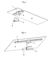
- the from the Figures 1 and 2 apparent drainage device essentially comprises a gutter-shaped drain body 1, an at least partially plate-shaped part 2 and a drain pot. 3
- the gutter-shaped drain body 1 consists for example of plastic and / or steel and has in the position of use an upper elongated inlet opening (not shown) through which Wastewater can enter the gutter.
- a cover element (not shown) can be arranged in or on the channel.
- the inlet opening may extend between the channel and the cover element, in particular around the cover element.
- a nozzle 4 is formed or attached, which has an outlet opening 5, through which the wastewater located in the gutter can escape.
- the at least partially plate-shaped part 2 may for example consist of mineral casting.
- materials conceivable that can serve as a surface for a shower area For example, wood, preferably impregnated wood, could also be used.
- the at least partially plate-shaped part 2 can have a finished, upper surface in the installed position, so that it can itself form the surface of the shower area. As a result, the assembly is significantly simplified, because after installation of the connected to the drain body 1 Part 2 no further action must be taken to achieve an attractive surface of the shower area.
- the at least partially plate-shaped part 2 serves as a support surface for tiles or another floor covering.
- trough-shaped drain body 1 and the at least partially plate-shaped part 2 are preassembled into a unit. This can be realized for example by gluing and / or screwing.
- the drain pot 3 can be preassembled in the bottom of the damp room.
- the drain pot 3 has a drain port 6, which can be connected to a drain line.
- drain port 6 In the open-top drain pot 3 can be introduced 4 as part of the assembly.
- drain pan 3 and trough-shaped drain body 1 can be screwed together.
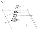
- This embodiment is designed so that the trough-shaped drain body 1 can be arranged in the plate-shaped part 2.
- the underside of the drain body 1 in the preassembled state is flush with the underside of the plate-shaped part 2 (see Fig. 5 ).
- the top of the drain body 1 in the preassembled state is flush with the top of the plate-shaped part 2 from. Due to the fact that the trough-shaped drain body 1 is arranged in the plate-shaped part 2 and protrudes in the installation position neither down nor up over the plate-shaped part 2, the preassembled unit can be easily stacked.
- a sealing insert 7 can be screwed, which can be inserted into the drain pan 3 from above.
- an odor trap unit 8 shown, which can be introduced from above into the gutter-shaped drain body 1.
- the drain body 1 also has a lateral chamfer 9, which corresponds to a chamfer 10 of the plate-shaped part 2.
- bevel 9 is on the one hand entering the waste water in the inlet opening 11 favors.
- the chamfer 9 continues the chamfer 10 provided in the plate-shaped part 2, so that an appealing appearance of the drainage device results.
Landscapes
- Health & Medical Sciences (AREA)
- Public Health (AREA)
- Epidemiology (AREA)
- General Health & Medical Sciences (AREA)
- Life Sciences & Earth Sciences (AREA)
- Engineering & Computer Science (AREA)
- Hydrology & Water Resources (AREA)
- Water Supply & Treatment (AREA)
- Sink And Installation For Waste Water (AREA)
- Residential Or Office Buildings (AREA)
- Bathtubs, Showers, And Their Attachments (AREA)
Abstract
Description
- Die vorliegende Erfindung betrifft eine Ablaufvorrichtung für einen Feuchtraum, insbesondere für eine Dusche, gemäß dem Oberbegriff des Anspruchs 1.
- Derartige Ablaufvorrichtungen sind bekannt. Sie finden beispielsweise bei barrierefreien Duschen Verwendung. Dabei können plattenförmige Teile beispielsweise als Auflagefläche für Fliesen dienen oder bereits selbst Teil der Oberfläche des Duschenbodens sein. Als nachteilig bei derartigen Ablaufvorrichtungen erweist sich die in der Regel sehr umständliche Montage.
- Das der vorliegenden Erfindung zugrunde liegende Problem ist die Schaffung einer Ablaufvorrichtung der eingangs genannten Art, die ein ansprechenderes Äußeres bietet und/oder bei der das Abwasser einfacher in die Einlauföffnung eintreten kann.
- Dies wird erfindungsgemäß durch eine Ablaufvorrichtung der eingangs genannten Art mit den kennzeichnenden Merkmalen des Anspruchs 1. Die Unteransprüche betreffen bevorzugte Ausgestaltungen der Erfindung.
- Gemäß Anspruch 1 ist vorgesehen, dass der rinnenförmige Ablaufkörper im Bereich der Einlauföffnung mindestens eine Anschrägung aufweist. Durch die Anschrägung wird das Eintreten des Abwassers in die Einlauföffnung begünstigt. Weiterhin kann die Anschrägung eine beispielsweise in dem plattenförmigen Teil vorgesehene Anschrägung fortsetzen, so dass sich ein ansprechendes Äußeres der Ablaufvorrichtung ergibt.
- Es kann weiterhin vorgesehen sein, dass der rinnenförmige Ablaufkörper und ein zumindest abschnittsweise plattenförmiges Teil zu einer Einheit vormontiert sind. Dadurch wird die Montage wesentlich erleichtert.
- Beispielsweise können dabei der rinnenförmige Ablaufkörper und das zumindest abschnittsweise plattenförmige Teil lösbar und/oder unlösbar miteinander verbunden sein, insbesondere miteinander verklebt und/oder verschraubt sein.
- Es kann vorgesehen sein, dass der rinnenförmige Ablaufkörper in dem plattenförmigen Teil angeordnet ist und in Einbaulage insbesondere weder oben noch unten über das plattenförmige Teil hinausragt. Dadurch lässt sich die vormontierte Einheit aus rinnenförmigem Ablaufkörper und plattenförmigem Teil problemlos stapeln.
- Weitere Merkmale und Vorteile der vorliegenden Erfindung werden deutlich anhand der nachfolgenden Beschreibung bevorzugter Ausführungsbeispiele unter Bezugnahme auf die beiliegenden Abbildungen. Darin zeigen
- Fig. 1
- eine perspektivische Explosionsdarstellung einer ersten Ausführungsform einer erfindungsgemäßen Ablaufvorrichtung;
- Fig. 2
- eine weitere perspektivische Explosionsdarstellung der ersten Ausführungsform einer erfindungsgemäßen Ablaufvorrichtung;
- Fig. 3
- eine perspektivische Explosionsdarstellung einer zweiten Ausführungsform einer erfindungsgemäßen Ablaufvorrichtung;
- Fig. 4
- einen Schnitt durch die zweite Ausführungsform einer erfindungsgemäßen Ablaufvorrichtung im montierten Zustand;
- Fig. 5
- eine weitere perspektivische Explosionsdarstellung der zweiten Ausführungsform einer erfindungsgemäßen Ablaufvorrichtung.
- Die aus den
Figuren 1 und 2 ersichtliche Ablaufvorrichtung umfasst im wesentlichen einen rinnenförmigen Ablaufkörper 1, ein zumindest abschnittsweise plattenförmiges Teil 2 und einen Ablauftopf 3. - Der rinnenförmige Ablaufkörper 1 besteht beispielsweise aus Kunststoff und/oder Stahl und weist in Gebrauchslage eine obere langgestreckte Einlauföffnung auf (nicht abgebildet), durch die Abwasser in die Rinne eintreten kann. Beispielsweise kann in oder auf der Rinne ein Abdeckelement (nicht abgebildet) angeordnet werden. Zwischen der Rinne und dem Abdeckelement kann sich die Einlauföffnung erstrecken, insbesondere um das Abdeckelement herum. An der in Gebrauchslage unteren Seite des rinnenförmigen Ablaufkörpers 1 ist ein Stutzen 4 angeformt oder angebracht, der eine Auslassöffnung 5 aufweist, durch die das in der Rinne befindliche Abwasser austreten kann.
- Das zumindest abschnittsweise plattenförmige Teil 2 kann beispielsweise aus Mineralguss bestehen. Hier sind auch andere Materialien denkbar, die als Oberfläche für einen Duschbereich dienen können. Beispielsweise könnte auch Holz, vorzugsweise imprägniertes Holz Verwendung finden. Das zumindest abschnittsweise plattenförmige Teil 2 kann eine fertig bearbeitete, in Einbaulage obere, Oberfläche aufweisen, so dass es selbst die Oberfläche des Duschbereichs bilden kann. Dadurch wird die Montage deutlich vereinfacht, weil nach dem Einbau des mit dem Ablaufkörper 1 verbundenen Teils 2 keine weiteren Maßnahmen mehr ergriffen werden müssen, um eine ansprechende Oberfläche des Duschbereichs zu erzielen.
- Alternativ besteht auch die Möglichkeit, dass das zumindest abschnittsweise plattenförmige Teil 2 als Auflagefläche für Fliesen oder einen anderen Bodenbelag dient.
- Erfindungsgemäß sind der rinnenförmige Ablaufkörper 1 und das zumindest abschnittsweise plattenförmige Teil 2 zu einer Einheit vormontiert sind. Dies kann beispielsweise durch Verkleben und/oder Verschrauben realisiert werden.
- Der Ablauftopf 3 kann im Boden des Feuchtraums vormontiert werden. Der Ablauftopf 3 weist einen Ablaufstutzen 6 auf, der mit einer Ablaufleitung verbunden werden kann. In den oben offenen Ablauftopf 3 kann im Rahmen der Montage der Stutzen 4 eingebracht werden. Dabei können Ablauftopf 3 und rinnenförmiger Ablaufkörper 1 miteinander verschraubt werden.
- Bei der zweiten Ausführungsform gemäß den
Figuren 3 bis 5 sind gleiche oder funktional gleiche Teile mit gleichen Bezugszeichen versehen wie in denFiguren 1 und 2 . - Diese Ausführungsform ist so gestaltet, dass der rinnenförmige Ablaufkörper 1 in dem plattenförmigen Teil 2 angeordnet werden kann. Insbesondere schließt die Unterseite des Ablaufkörpers 1 im vormontierten Zustand bündig mit der Unterseite des plattenförmigen Teils 2 ab (siehe
Fig. 5 ). Weiterhin schließt auch die Oberseite des Ablaufkörpers 1 im vormontierten Zustand bündig mit der Oberseite des plattenförmigen Teils 2 ab. Aufgrund der Tatsache, dass der rinnenförmige Ablaufkörper 1 in dem plattenförmigen Teil 2 angeordnet ist und in Einbaulage weder nach unten noch nach oben über das plattenförmige Teil 2 hinausragt, kann die vormontierte Einheit einfach gestapelt werden. - An die Unterseite des vormontierten Ablaufkörpers 1 kann ein Dichteinsatz 7 angeschraubt werden, der in den Ablauftopf 3 von oben eingeschoben werden kann. Zusätzlich ist in den
Fig. 3 bis Fig. 5 noch eine Geruchsverschlusseinheit 8 abgebildet, die von oben in den rinnenförmigen Ablaufkörper 1 eingebracht werden kann. - Der Ablaufkörper 1 weist weiterhin eine seitliche Anschrägung 9 auf, die zu einer Anschrägung 10 des plattenförmigen Teils 2 korrespondiert. Durch die Anschrägung 9 wird einerseits das Eintreten des Abwassers in die Einlauföffnung 11 begünstigt. Andererseits setzt die Anschrägung 9 die in dem plattenförmigen Teil 2 vorgesehene Anschrägung 10 fort, so dass sich ein ansprechendes Äußeres der Ablaufvorrichtung ergibt.
Claims (15)
- Ablaufvorrichtung für einen Feuchtraum, insbesondere für eine Dusche, umfassend einen rinnenförmigen Ablaufkörper (1) mit einer Einlauföffnung (11), in die Abwasser eintreten kann, wobei der Ablaufkörper (1) mindestens eine Auslassöffnung (5) aufweist, aus der das Abwasser austreten kann, dadurch gekennzeichnet, dass der rinnenförmige Ablaufkörper (1) im Bereich der Einlauföffnung (11) mindestens eine Anschrägung (9) aufweist, durch die das Eintreten des Abwassers in die Einlauföffnung (11) begünstigt wird.
- Ablaufvorrichtung nach Anspruch 1, dadurch gekennzeichnet, dass die Ablaufvorrichtung ein zumindest abschnittsweise plattenförmiges Teil (2) umfasst, das Teil eines Bodens des Feuchtraums, insbesondere der Dusche, sein kann, wobei der rinnenförmige Ablaufkörper (1) und das zumindest abschnittsweise plattenförmige Teil (2) zu einer Einheit vormontiert sind.
- Ablaufvorrichtung nach Anspruch 2, dadurch gekennzeichnet, dass der rinnenförmige Ablaufkörper (1) und das zumindest abschnittsweise plattenförmige Teil (2) lösbar und/oder unlösbar miteinander verbunden sind.
- Ablaufvorrichtung nach Anspruch 3, dadurch gekennzeichnet, dass der rinnenförmige Ablaufkörper (1) und das zumindest abschnittsweise plattenförmige Teil (2) miteinander verklebt und/oder miteinander verschweißt sind.
- Ablaufvorrichtung nach einem der Ansprüche 2 oder 3, dadurch gekennzeichnet, dass der rinnenförmige Ablaufkörper (1) und das zumindest abschnittsweise plattenförmige Teil (2) miteinander verschraubt und/oder miteinander verklipst und/oder miteinander verrastet und/oder durch Einschieben, wie beispielsweise in eine Schwalbenschanzführung, miteinander verbunden sind.
- Ablaufvorrichtung nach einem der Ansprüche 1 bis 5, dadurch gekennzeichnet, dass der rinnenförmige Ablaufkörper (1) zumindest teilweise aus Kunststoff besteht.
- Ablaufvorrichtung nach einem der Ansprüche 1 bis 6, dadurch gekennzeichnet, dass der rinnenförmige Ablaufkörper (1) zumindest teilweise aus Metall, insbesondere Stahl, besteht.
- Ablaufvorrichtung nach einem der Ansprüche 2 bis 7, dadurch gekennzeichnet, dass das zumindest abschnittsweise plattenförmige Teil (2) eine bearbeitete, in Einbaulage obere, Oberfläche aufweist, die insbesondere gebrauchsfertig bearbeitet ist.
- Ablaufvorrichtung nach einem der Ansprüche 2 bis 8, dadurch gekennzeichnet, dass das zumindest abschnittsweise plattenförmige Teil (2) zumindest teilweise aus Mineralguss besteht.
- Ablaufvorrichtung nach einem der Ansprüche 1 bis 9, dadurch gekennzeichnet, dass die Ablaufvorrichtung einen Ablauftopf (3) aufweist, der in dem Boden des Feuchtraums vormontiert werden kann.
- Ablaufvorrichtung nach einem der Ansprüche 1 bis 10, dadurch gekennzeichnet, dass der rinnenförmige Ablaufkörper (1) einen in Einbaulage unteren Stutzen (4) aufweist.
- Ablaufvorrichtung nach Anspruch 11, dadurch gekennzeichnet, dass der Stutzen (4) des rinnenförmigen Ablaufkörpers (1) bei der Montage von oben in den im Boden befindlichen Ablauftopf (3) eingreifen kann.
- Ablaufvorrichtung nach einem der Ansprüche 10 bis 12, dadurch gekennzeichnet, dass der rinnenförmige Ablaufkörper (1) mit dem Ablauftopf (3) verschraubt werden kann.
- Ablaufvorrichtung nach einem der Ansprüche 2 bis 13, dadurch gekennzeichnet, dass der rinnenförmige Ablaufkörper (1) in dem plattenförmigen Teil (2) angeordnet ist und in Einbaulage nicht nach unten, vorzugsweise auch nicht nach oben, über das plattenförmige Teil (2) hinausragt.
- Ablaufvorrichtung nach Anspruch 11, dadurch gekennzeichnet, dass die Ablaufvorrichtung einen Dichteinsatz (7) umfasst, der in Einbaulage von unten an dem vormontierten rinnenförmigen Ablaufkörper (1) angebracht, vorzugsweise angeschraubt, werden kann, wobei der Dichteinsatz (7) mit dem Ablauftopf (3) verbindbar ist.
Priority Applications (1)
| Application Number | Priority Date | Filing Date | Title |
|---|---|---|---|
| PL10002508T PL2196587T3 (pl) | 2007-11-30 | 2008-11-24 | Urządzenie odpływowe |
Applications Claiming Priority (3)
| Application Number | Priority Date | Filing Date | Title |
|---|---|---|---|
| DE102007058028 | 2007-11-30 | ||
| DE102008046671A DE102008046671A1 (de) | 2007-11-30 | 2008-09-10 | Ablaufvorrichtung |
| EP08020387.0A EP2065524B1 (de) | 2007-11-30 | 2008-11-24 | Ablaufvorrichtung |
Related Parent Applications (2)
| Application Number | Title | Priority Date | Filing Date |
|---|---|---|---|
| EP08020387.0A Division-Into EP2065524B1 (de) | 2007-11-30 | 2008-11-24 | Ablaufvorrichtung |
| EP08020387.0 Division | 2008-11-24 |
Publications (3)
| Publication Number | Publication Date |
|---|---|
| EP2196587A2 true EP2196587A2 (de) | 2010-06-16 |
| EP2196587A3 EP2196587A3 (de) | 2010-08-25 |
| EP2196587B1 EP2196587B1 (de) | 2013-04-24 |
Family
ID=40586043
Family Applications (2)
| Application Number | Title | Priority Date | Filing Date |
|---|---|---|---|
| EP08020387.0A Active EP2065524B1 (de) | 2007-11-30 | 2008-11-24 | Ablaufvorrichtung |
| EP10002508.9A Not-in-force EP2196587B1 (de) | 2007-11-30 | 2008-11-24 | Ablaufvorrichtung |
Family Applications Before (1)
| Application Number | Title | Priority Date | Filing Date |
|---|---|---|---|
| EP08020387.0A Active EP2065524B1 (de) | 2007-11-30 | 2008-11-24 | Ablaufvorrichtung |
Country Status (7)
| Country | Link |
|---|---|
| EP (2) | EP2065524B1 (de) |
| DE (1) | DE102008046671A1 (de) |
| DK (2) | DK2065524T3 (de) |
| ES (2) | ES2854849T3 (de) |
| PL (2) | PL2196587T3 (de) |
| PT (1) | PT2065524T (de) |
| SI (1) | SI2065524T1 (de) |
Families Citing this family (12)
| Publication number | Priority date | Publication date | Assignee | Title |
|---|---|---|---|---|
| BE1019528A5 (nl) * | 2010-10-05 | 2012-08-07 | Aquadraat Engineering Bvba | Dal en werkwijze voor het vervaardigen van een dal en hemelwaterafvoersysteem voorzien van zulke dal. |
| NL2005864C2 (nl) * | 2010-12-16 | 2012-06-19 | Easy Sanitairy Solutions Bv | Vlakke plaat goot. |
| DE102011000342A1 (de) * | 2011-01-26 | 2012-07-26 | Franz Kaldewei Gmbh & Co. Kg | Sanitäranordnung, insbesondere bodengleiche Dusche |
| DE202012100725U1 (de) | 2011-11-10 | 2013-02-14 | Poresta Systems Gmbh | Duschbodenelement und Einbauset für ein Duschbodenelement |
| EP2591709B1 (de) | 2011-11-10 | 2018-03-21 | poresta systems GmbH | Duschbodenelement und Einbauset für ein Duschbodenelement |
| DE102012110726A1 (de) | 2011-11-10 | 2013-05-16 | Poresta Systems Gmbh | Duschbodenelement und Einbauset für ein Duschbodenelement |
| EP2687136B1 (de) | 2012-07-20 | 2017-03-15 | Dallmer GmbH & Co. KG | Duschelement |
| DE102013105542A1 (de) | 2013-05-29 | 2014-12-04 | Wedi Gmbh | Wasserablaufvorrichtung für eine Dusche und Duschbodenelement |
| IL230110A0 (en) * | 2013-12-23 | 2014-03-31 | Huliot A C S Ltd | Kit for linear floor drainage |
| ES2555671B1 (es) * | 2014-07-04 | 2016-09-20 | Baroan Rioja, S.L. | Dispositivo de desagüe con orificio de entrada no circular |
| DE102016125311A1 (de) * | 2016-12-22 | 2018-06-28 | Wedi Gmbh | Wasserablauf für einen Duschboden mit einem universell einsetzbaren Anschlussadapter |
| US12421134B2 (en) | 2020-06-26 | 2025-09-23 | Orbital Systems Ab | System for water quality measurement and a recirculation system comprising the same |
Citations (3)
| Publication number | Priority date | Publication date | Assignee | Title |
|---|---|---|---|---|
| GB2388144A (en) | 2002-04-29 | 2003-11-05 | Alumasc Ltd | Slot drain for roads, car parks, warehouses etc. |
| EP1782721A2 (de) | 2005-11-02 | 2007-05-09 | VIEGA GmbH & Co. KG. | Trägerelement für Duschtasse |
| DE102006007471A1 (de) | 2006-02-17 | 2007-08-30 | Basika Entwässerungstechnik GmbH & Co. KG | Duschbodenelement und Trägerelement dafür, sowie Duschbodenunterbau aus einem Duschbodenelement und einem Trägerelement für bodengleiche Duschen |
Family Cites Families (5)
| Publication number | Priority date | Publication date | Assignee | Title |
|---|---|---|---|---|
| AT327819B (de) * | 1974-11-19 | 1976-02-25 | Guggemos Horst | Sohlschale fur gerinne, insbesondere fur kanale |
| DE9103590U1 (de) * | 1991-03-23 | 1991-06-27 | Birco Baustoffwerk GmbH, 7570 Baden-Baden | Abflußrinne mit oberseitiger Abdeckung |
| FR2846348A1 (fr) * | 2002-10-28 | 2004-04-30 | Marc Gabriel Jean M Dombrowski | Procede et dispositif pour realiser une reservation etanche dans du beton et permettant de rendre etanches les conduits existants, utilisant un film plastique |
| GB2415455B (en) * | 2004-06-22 | 2009-03-25 | Quintin Anthony Murfin | Controlled filter strip |
| FR2928156B1 (fr) * | 2008-02-29 | 2014-05-23 | Farhooman Davoudi | Ensemble bonde/siphon d'evacuation compose de plusieurs gardes d'eau |
-
2008
- 2008-09-10 DE DE102008046671A patent/DE102008046671A1/de not_active Ceased
- 2008-11-24 EP EP08020387.0A patent/EP2065524B1/de active Active
- 2008-11-24 ES ES08020387T patent/ES2854849T3/es active Active
- 2008-11-24 DK DK08020387.0T patent/DK2065524T3/da active
- 2008-11-24 ES ES10002508T patent/ES2422711T3/es active Active
- 2008-11-24 PT PT80203870T patent/PT2065524T/pt unknown
- 2008-11-24 PL PL10002508T patent/PL2196587T3/pl unknown
- 2008-11-24 EP EP10002508.9A patent/EP2196587B1/de not_active Not-in-force
- 2008-11-24 SI SI200832156T patent/SI2065524T1/sl unknown
- 2008-11-24 DK DK10002508.9T patent/DK2196587T3/da active
- 2008-11-24 PL PL08020387T patent/PL2065524T3/pl unknown
Patent Citations (3)
| Publication number | Priority date | Publication date | Assignee | Title |
|---|---|---|---|---|
| GB2388144A (en) | 2002-04-29 | 2003-11-05 | Alumasc Ltd | Slot drain for roads, car parks, warehouses etc. |
| EP1782721A2 (de) | 2005-11-02 | 2007-05-09 | VIEGA GmbH & Co. KG. | Trägerelement für Duschtasse |
| DE102006007471A1 (de) | 2006-02-17 | 2007-08-30 | Basika Entwässerungstechnik GmbH & Co. KG | Duschbodenelement und Trägerelement dafür, sowie Duschbodenunterbau aus einem Duschbodenelement und einem Trägerelement für bodengleiche Duschen |
Also Published As
| Publication number | Publication date |
|---|---|
| PT2065524T (pt) | 2021-03-04 |
| PL2196587T3 (pl) | 2013-09-30 |
| EP2196587A3 (de) | 2010-08-25 |
| EP2196587B1 (de) | 2013-04-24 |
| EP2065524B1 (de) | 2020-12-16 |
| EP2065524A2 (de) | 2009-06-03 |
| SI2065524T1 (sl) | 2021-07-30 |
| DE102008046671A1 (de) | 2009-06-04 |
| EP2065524A3 (de) | 2009-10-21 |
| ES2422711T3 (es) | 2013-09-13 |
| DK2196587T3 (da) | 2013-07-29 |
| ES2854849T3 (es) | 2021-09-23 |
| DK2065524T3 (da) | 2021-03-08 |
| PL2065524T3 (pl) | 2021-06-28 |
Similar Documents
| Publication | Publication Date | Title |
|---|---|---|
| EP2196587B1 (de) | Ablaufvorrichtung | |
| EP2481332B1 (de) | Sanitäranordnung, insbesondere bodengleiche Dusche | |
| DE202015105638U1 (de) | Bodenablauf | |
| EP1908887A1 (de) | Bodenablauf, insbesondere in Form einer Duschrinne | |
| EP2711475B1 (de) | Spüle mit einer belüfteten Ablaufeinrichtung | |
| DE202006014440U1 (de) | Duschbodenelement aus einem Hartschaumstoff | |
| EP2756137B1 (de) | Ablaufrinne für eine bodengleiche dusche | |
| EP3293317B1 (de) | Ablaufvorrichtung zur ableitung von wasser | |
| EP2221420B1 (de) | Ablaufvorrichtung | |
| EP2634321B1 (de) | Ablaufrinne | |
| DE202007006050U1 (de) | Ablaufvorrichtung für die zumindest teilweise Einbringung in einen Boden eines Raumes | |
| EP2258905B1 (de) | Ablauf, insbesondere für sanitäre Einrichtungen | |
| EP1544360A1 (de) | Ablaufvorrichtung | |
| DE102012106924A1 (de) | Ablaufanordnung | |
| DE102008059514A1 (de) | Ablaufvorrichtung | |
| DE102006051130B4 (de) | Ablaufvorrichtung für die zumindest teilweise Einbringung in einen Boden eines Raumes | |
| WO2015043875A1 (de) | Sanitärzelle für ein schienenfahrzeug | |
| WO2017067718A1 (de) | Bodenablauf mit geruchsverschluss | |
| DE202011004001U1 (de) | Ablaufanordnung | |
| DE102021103470A1 (de) | Sanitärbodenelement und Kombination eines Sanitärbodenelements mit einer Wandablaufvorrichtung | |
| EP3375944B1 (de) | Entwässerungsrinne, verfahren zur herstellung und verfahren zum einbau | |
| DE4212205A1 (de) | Schwimmbad-Ablaufsystem | |
| DE10204683A1 (de) | Becken | |
| EP2759646A2 (de) | Vorrichtung für einen in der Nähe einer Wand angeordneten Bodenablauf | |
| DE202014100718U1 (de) | Entwässerungseinrichtung zur Abführung von Oberflächenwasser |
Legal Events
| Date | Code | Title | Description |
|---|---|---|---|
| PUAI | Public reference made under article 153(3) epc to a published international application that has entered the european phase |
Free format text: ORIGINAL CODE: 0009012 |
|
| AC | Divisional application: reference to earlier application |
Ref document number: 2065524 Country of ref document: EP Kind code of ref document: P |
|
| AK | Designated contracting states |
Kind code of ref document: A2 Designated state(s): AT BE BG CH CY CZ DE DK EE ES FI FR GB GR HR HU IE IS IT LI LT LU LV MC MT NL NO PL PT RO SE SI SK TR |
|
| AX | Request for extension of the european patent |
Extension state: AL BA MK RS |
|
| PUAL | Search report despatched |
Free format text: ORIGINAL CODE: 0009013 |
|
| AK | Designated contracting states |
Kind code of ref document: A3 Designated state(s): AT BE BG CH CY CZ DE DK EE ES FI FR GB GR HR HU IE IS IT LI LT LU LV MC MT NL NO PL PT RO SE SI SK TR |
|
| AX | Request for extension of the european patent |
Extension state: AL BA MK RS |
|
| 17P | Request for examination filed |
Effective date: 20110225 |
|
| 17Q | First examination report despatched |
Effective date: 20110421 |
|
| REG | Reference to a national code |
Ref country code: DE Ref legal event code: R079 Ref document number: 502008009812 Country of ref document: DE Free format text: PREVIOUS MAIN CLASS: E03F0003040000 Ipc: E03F0005040000 |
|
| GRAP | Despatch of communication of intention to grant a patent |
Free format text: ORIGINAL CODE: EPIDOSNIGR1 |
|
| RIC1 | Information provided on ipc code assigned before grant |
Ipc: E03F 5/04 20060101AFI20121113BHEP |
|
| GRAS | Grant fee paid |
Free format text: ORIGINAL CODE: EPIDOSNIGR3 |
|
| GRAA | (expected) grant |
Free format text: ORIGINAL CODE: 0009210 |
|
| AC | Divisional application: reference to earlier application |
Ref document number: 2065524 Country of ref document: EP Kind code of ref document: P |
|
| AK | Designated contracting states |
Kind code of ref document: B1 Designated state(s): AT BE BG CH CY CZ DE DK EE ES FI FR GB GR HR HU IE IS IT LI LT LU LV MC MT NL NO PL PT RO SE SI SK TR |
|
| REG | Reference to a national code |
Ref country code: GB Ref legal event code: FG4D Free format text: NOT ENGLISH |
|
| REG | Reference to a national code |
Ref country code: CH Ref legal event code: EP |
|
| REG | Reference to a national code |
Ref country code: AT Ref legal event code: REF Ref document number: 608735 Country of ref document: AT Kind code of ref document: T Effective date: 20130515 |
|
| REG | Reference to a national code |
Ref country code: IE Ref legal event code: FG4D Free format text: LANGUAGE OF EP DOCUMENT: GERMAN |
|
| REG | Reference to a national code |
Ref country code: DE Ref legal event code: R096 Ref document number: 502008009812 Country of ref document: DE Effective date: 20130620 |
|
| REG | Reference to a national code |
Ref country code: DK Ref legal event code: T3 |
|
| REG | Reference to a national code |
Ref country code: SE Ref legal event code: TRGR |
|
| REG | Reference to a national code |
Ref country code: ES Ref legal event code: FG2A Ref document number: 2422711 Country of ref document: ES Kind code of ref document: T3 Effective date: 20130913 |
|
| RAP2 | Party data changed (patent owner data changed or rights of a patent transferred) |
Owner name: WEDI GMBH |
|
| REG | Reference to a national code |
Ref country code: NL Ref legal event code: T3 |
|
| REG | Reference to a national code |
Ref country code: DE Ref legal event code: R082 Ref document number: 502008009812 Country of ref document: DE Representative=s name: DR. HOFFMEISTER & BISCHOF, PATENTANWALT UND RE, DE Ref country code: LT Ref legal event code: MG4D |
|
| REG | Reference to a national code |
Ref country code: PL Ref legal event code: T3 |
|
| PG25 | Lapsed in a contracting state [announced via postgrant information from national office to epo] |
Ref country code: SI Free format text: LAPSE BECAUSE OF FAILURE TO SUBMIT A TRANSLATION OF THE DESCRIPTION OR TO PAY THE FEE WITHIN THE PRESCRIBED TIME-LIMIT Effective date: 20130424 Ref country code: FI Free format text: LAPSE BECAUSE OF FAILURE TO SUBMIT A TRANSLATION OF THE DESCRIPTION OR TO PAY THE FEE WITHIN THE PRESCRIBED TIME-LIMIT Effective date: 20130424 Ref country code: GR Free format text: LAPSE BECAUSE OF FAILURE TO SUBMIT A TRANSLATION OF THE DESCRIPTION OR TO PAY THE FEE WITHIN THE PRESCRIBED TIME-LIMIT Effective date: 20130725 Ref country code: IS Free format text: LAPSE BECAUSE OF FAILURE TO SUBMIT A TRANSLATION OF THE DESCRIPTION OR TO PAY THE FEE WITHIN THE PRESCRIBED TIME-LIMIT Effective date: 20130824 Ref country code: LT Free format text: LAPSE BECAUSE OF FAILURE TO SUBMIT A TRANSLATION OF THE DESCRIPTION OR TO PAY THE FEE WITHIN THE PRESCRIBED TIME-LIMIT Effective date: 20130424 Ref country code: NO Free format text: LAPSE BECAUSE OF FAILURE TO SUBMIT A TRANSLATION OF THE DESCRIPTION OR TO PAY THE FEE WITHIN THE PRESCRIBED TIME-LIMIT Effective date: 20130724 Ref country code: PT Free format text: LAPSE BECAUSE OF FAILURE TO SUBMIT A TRANSLATION OF THE DESCRIPTION OR TO PAY THE FEE WITHIN THE PRESCRIBED TIME-LIMIT Effective date: 20130826 |
|
| REG | Reference to a national code |
Ref country code: NL Ref legal event code: SD Effective date: 20131105 |
|
| REG | Reference to a national code |
Ref country code: DE Ref legal event code: R082 Ref document number: 502008009812 Country of ref document: DE Representative=s name: BISCHOF & PARTNER RECHTSANWAELTE PARTNERSCHAFT, DE Effective date: 20130925 Ref country code: DE Ref legal event code: R082 Ref document number: 502008009812 Country of ref document: DE Representative=s name: MEISSNER, BOLTE & PARTNER GBR, DE Effective date: 20130925 Ref country code: DE Ref legal event code: R082 Ref document number: 502008009812 Country of ref document: DE Representative=s name: DR. HOFFMEISTER & BISCHOF, PATENTANWALT UND RE, DE Effective date: 20130925 Ref country code: DE Ref legal event code: R081 Ref document number: 502008009812 Country of ref document: DE Owner name: WEDI GMBH, DE Free format text: FORMER OWNER: DALLMER GMBH & CO. KG, 59757 ARNSBERG, DE Effective date: 20130925 Ref country code: DE Ref legal event code: R082 Ref document number: 502008009812 Country of ref document: DE Representative=s name: MEISSNER BOLTE PATENTANWAELTE RECHTSANWAELTE P, DE Effective date: 20130925 |
|
| PG25 | Lapsed in a contracting state [announced via postgrant information from national office to epo] |
Ref country code: HR Free format text: LAPSE BECAUSE OF FAILURE TO SUBMIT A TRANSLATION OF THE DESCRIPTION OR TO PAY THE FEE WITHIN THE PRESCRIBED TIME-LIMIT Effective date: 20130424 Ref country code: CY Free format text: LAPSE BECAUSE OF FAILURE TO SUBMIT A TRANSLATION OF THE DESCRIPTION OR TO PAY THE FEE WITHIN THE PRESCRIBED TIME-LIMIT Effective date: 20130424 Ref country code: LV Free format text: LAPSE BECAUSE OF FAILURE TO SUBMIT A TRANSLATION OF THE DESCRIPTION OR TO PAY THE FEE WITHIN THE PRESCRIBED TIME-LIMIT Effective date: 20130424 Ref country code: BG Free format text: LAPSE BECAUSE OF FAILURE TO SUBMIT A TRANSLATION OF THE DESCRIPTION OR TO PAY THE FEE WITHIN THE PRESCRIBED TIME-LIMIT Effective date: 20130724 |
|
| REG | Reference to a national code |
Ref country code: CH Ref legal event code: PUE Owner name: WEDI GMBH, DE Free format text: FORMER OWNER: DALLMER GMBH AND CO. KG, DE Ref country code: CH Ref legal event code: NV Representative=s name: SPIERENBURG AND PARTNER AG, PATENT- UND MARKEN, CH |
|
| REG | Reference to a national code |
Ref country code: GB Ref legal event code: 732E Free format text: REGISTERED BETWEEN 20131114 AND 20131120 |
|
| REG | Reference to a national code |
Ref country code: FR Ref legal event code: TP Owner name: WEDI GMBH, DE Effective date: 20131219 |
|
| PG25 | Lapsed in a contracting state [announced via postgrant information from national office to epo] |
Ref country code: SK Free format text: LAPSE BECAUSE OF FAILURE TO SUBMIT A TRANSLATION OF THE DESCRIPTION OR TO PAY THE FEE WITHIN THE PRESCRIBED TIME-LIMIT Effective date: 20130424 Ref country code: CZ Free format text: LAPSE BECAUSE OF FAILURE TO SUBMIT A TRANSLATION OF THE DESCRIPTION OR TO PAY THE FEE WITHIN THE PRESCRIBED TIME-LIMIT Effective date: 20130424 Ref country code: EE Free format text: LAPSE BECAUSE OF FAILURE TO SUBMIT A TRANSLATION OF THE DESCRIPTION OR TO PAY THE FEE WITHIN THE PRESCRIBED TIME-LIMIT Effective date: 20130424 |
|
| PG25 | Lapsed in a contracting state [announced via postgrant information from national office to epo] |
Ref country code: RO Free format text: LAPSE BECAUSE OF FAILURE TO SUBMIT A TRANSLATION OF THE DESCRIPTION OR TO PAY THE FEE WITHIN THE PRESCRIBED TIME-LIMIT Effective date: 20130424 |
|
| PLBE | No opposition filed within time limit |
Free format text: ORIGINAL CODE: 0009261 |
|
| STAA | Information on the status of an ep patent application or granted ep patent |
Free format text: STATUS: NO OPPOSITION FILED WITHIN TIME LIMIT |
|
| 26N | No opposition filed |
Effective date: 20140127 |
|
| REG | Reference to a national code |
Ref country code: DE Ref legal event code: R097 Ref document number: 502008009812 Country of ref document: DE Effective date: 20140127 |
|
| REG | Reference to a national code |
Ref country code: AT Ref legal event code: PC Ref document number: 608735 Country of ref document: AT Kind code of ref document: T Owner name: WEDI GMBH, DE Effective date: 20140409 |
|
| PG25 | Lapsed in a contracting state [announced via postgrant information from national office to epo] |
Ref country code: MC Free format text: LAPSE BECAUSE OF FAILURE TO SUBMIT A TRANSLATION OF THE DESCRIPTION OR TO PAY THE FEE WITHIN THE PRESCRIBED TIME-LIMIT Effective date: 20130424 |
|
| REG | Reference to a national code |
Ref country code: IE Ref legal event code: MM4A |
|
| PG25 | Lapsed in a contracting state [announced via postgrant information from national office to epo] |
Ref country code: IE Free format text: LAPSE BECAUSE OF NON-PAYMENT OF DUE FEES Effective date: 20131124 |
|
| REG | Reference to a national code |
Ref country code: DE Ref legal event code: R082 Ref document number: 502008009812 Country of ref document: DE Representative=s name: BISCHOF & PARTNER RECHTSANWAELTE PARTNERSCHAFT, DE Ref country code: DE Ref legal event code: R082 Ref document number: 502008009812 Country of ref document: DE Representative=s name: MEISSNER, BOLTE & PARTNER GBR, DE Ref country code: DE Ref legal event code: R082 Ref document number: 502008009812 Country of ref document: DE Representative=s name: MEISSNER BOLTE PATENTANWAELTE RECHTSANWAELTE P, DE |
|
| PG25 | Lapsed in a contracting state [announced via postgrant information from national office to epo] |
Ref country code: TR Free format text: LAPSE BECAUSE OF FAILURE TO SUBMIT A TRANSLATION OF THE DESCRIPTION OR TO PAY THE FEE WITHIN THE PRESCRIBED TIME-LIMIT Effective date: 20130424 |
|
| PG25 | Lapsed in a contracting state [announced via postgrant information from national office to epo] |
Ref country code: HU Free format text: LAPSE BECAUSE OF FAILURE TO SUBMIT A TRANSLATION OF THE DESCRIPTION OR TO PAY THE FEE WITHIN THE PRESCRIBED TIME-LIMIT; INVALID AB INITIO Effective date: 20081124 |
|
| PG25 | Lapsed in a contracting state [announced via postgrant information from national office to epo] |
Ref country code: MT Free format text: LAPSE BECAUSE OF FAILURE TO SUBMIT A TRANSLATION OF THE DESCRIPTION OR TO PAY THE FEE WITHIN THE PRESCRIBED TIME-LIMIT Effective date: 20130424 |
|
| REG | Reference to a national code |
Ref country code: DE Ref legal event code: R082 Ref document number: 502008009812 Country of ref document: DE Representative=s name: MEISSNER, BOLTE & PARTNER GBR, DE Ref country code: DE Ref legal event code: R082 Ref document number: 502008009812 Country of ref document: DE Representative=s name: MEISSNER BOLTE PATENTANWAELTE RECHTSANWAELTE P, DE |
|
| REG | Reference to a national code |
Ref country code: FR Ref legal event code: PLFP Year of fee payment: 8 |
|
| REG | Reference to a national code |
Ref country code: FR Ref legal event code: PLFP Year of fee payment: 9 |
|
| REG | Reference to a national code |
Ref country code: FR Ref legal event code: PLFP Year of fee payment: 10 |
|
| PGFP | Annual fee paid to national office [announced via postgrant information from national office to epo] |
Ref country code: LU Payment date: 20171108 Year of fee payment: 10 |
|
| PGFP | Annual fee paid to national office [announced via postgrant information from national office to epo] |
Ref country code: ES Payment date: 20171201 Year of fee payment: 10 Ref country code: AT Payment date: 20171026 Year of fee payment: 10 Ref country code: IT Payment date: 20171123 Year of fee payment: 10 Ref country code: PL Payment date: 20171124 Year of fee payment: 10 |
|
| REG | Reference to a national code |
Ref country code: FR Ref legal event code: PLFP Year of fee payment: 11 |
|
| PGFP | Annual fee paid to national office [announced via postgrant information from national office to epo] |
Ref country code: NL Payment date: 20181114 Year of fee payment: 11 |
|
| PGFP | Annual fee paid to national office [announced via postgrant information from national office to epo] |
Ref country code: DE Payment date: 20181025 Year of fee payment: 11 Ref country code: SE Payment date: 20181113 Year of fee payment: 11 Ref country code: DK Payment date: 20181109 Year of fee payment: 11 |
|
| PGFP | Annual fee paid to national office [announced via postgrant information from national office to epo] |
Ref country code: CH Payment date: 20181115 Year of fee payment: 11 Ref country code: GB Payment date: 20181121 Year of fee payment: 11 Ref country code: BE Payment date: 20181015 Year of fee payment: 11 Ref country code: FR Payment date: 20181026 Year of fee payment: 11 |
|
| REG | Reference to a national code |
Ref country code: AT Ref legal event code: MM01 Ref document number: 608735 Country of ref document: AT Kind code of ref document: T Effective date: 20181124 |
|
| PG25 | Lapsed in a contracting state [announced via postgrant information from national office to epo] |
Ref country code: LU Free format text: LAPSE BECAUSE OF NON-PAYMENT OF DUE FEES Effective date: 20181124 |
|
| PG25 | Lapsed in a contracting state [announced via postgrant information from national office to epo] |
Ref country code: IT Free format text: LAPSE BECAUSE OF NON-PAYMENT OF DUE FEES Effective date: 20181124 Ref country code: AT Free format text: LAPSE BECAUSE OF NON-PAYMENT OF DUE FEES Effective date: 20181124 |
|
| REG | Reference to a national code |
Ref country code: ES Ref legal event code: FD2A Effective date: 20200108 |
|
| PG25 | Lapsed in a contracting state [announced via postgrant information from national office to epo] |
Ref country code: ES Free format text: LAPSE BECAUSE OF NON-PAYMENT OF DUE FEES Effective date: 20181125 |
|
| REG | Reference to a national code |
Ref country code: DE Ref legal event code: R119 Ref document number: 502008009812 Country of ref document: DE |
|
| REG | Reference to a national code |
Ref country code: DK Ref legal event code: EBP Effective date: 20191130 |
|
| REG | Reference to a national code |
Ref country code: SE Ref legal event code: EUG Ref country code: CH Ref legal event code: PL |
|
| REG | Reference to a national code |
Ref country code: NL Ref legal event code: MM Effective date: 20191201 |
|
| PG25 | Lapsed in a contracting state [announced via postgrant information from national office to epo] |
Ref country code: LI Free format text: LAPSE BECAUSE OF NON-PAYMENT OF DUE FEES Effective date: 20191130 Ref country code: CH Free format text: LAPSE BECAUSE OF NON-PAYMENT OF DUE FEES Effective date: 20191130 |
|
| REG | Reference to a national code |
Ref country code: BE Ref legal event code: MM Effective date: 20191130 |
|
| PG25 | Lapsed in a contracting state [announced via postgrant information from national office to epo] |
Ref country code: PL Free format text: LAPSE BECAUSE OF NON-PAYMENT OF DUE FEES Effective date: 20181124 Ref country code: SE Free format text: LAPSE BECAUSE OF NON-PAYMENT OF DUE FEES Effective date: 20191125 |
|
| GBPC | Gb: european patent ceased through non-payment of renewal fee |
Effective date: 20191124 |
|
| PG25 | Lapsed in a contracting state [announced via postgrant information from national office to epo] |
Ref country code: NL Free format text: LAPSE BECAUSE OF NON-PAYMENT OF DUE FEES Effective date: 20191201 |
|
| PG25 | Lapsed in a contracting state [announced via postgrant information from national office to epo] |
Ref country code: DK Free format text: LAPSE BECAUSE OF NON-PAYMENT OF DUE FEES Effective date: 20191130 Ref country code: GB Free format text: LAPSE BECAUSE OF NON-PAYMENT OF DUE FEES Effective date: 20191124 Ref country code: FR Free format text: LAPSE BECAUSE OF NON-PAYMENT OF DUE FEES Effective date: 20191130 Ref country code: DE Free format text: LAPSE BECAUSE OF NON-PAYMENT OF DUE FEES Effective date: 20200603 |
|
| PG25 | Lapsed in a contracting state [announced via postgrant information from national office to epo] |
Ref country code: BE Free format text: LAPSE BECAUSE OF NON-PAYMENT OF DUE FEES Effective date: 20191130 |