EP2065573B1 - Joint de soupape de moteur à combustion interne - Google Patents
Joint de soupape de moteur à combustion interne Download PDFInfo
- Publication number
- EP2065573B1 EP2065573B1 EP20080170310 EP08170310A EP2065573B1 EP 2065573 B1 EP2065573 B1 EP 2065573B1 EP 20080170310 EP20080170310 EP 20080170310 EP 08170310 A EP08170310 A EP 08170310A EP 2065573 B1 EP2065573 B1 EP 2065573B1
- Authority
- EP
- European Patent Office
- Prior art keywords
- valve
- axis
- gasket
- stem
- supporting element
- Prior art date
- Legal status (The legal status is an assumption and is not a legal conclusion. Google has not performed a legal analysis and makes no representation as to the accuracy of the status listed.)
- Active
Links
Images

Classifications
-
- F—MECHANICAL ENGINEERING; LIGHTING; HEATING; WEAPONS; BLASTING
- F01—MACHINES OR ENGINES IN GENERAL; ENGINE PLANTS IN GENERAL; STEAM ENGINES
- F01L—CYCLICALLY OPERATING VALVES FOR MACHINES OR ENGINES
- F01L3/00—Lift-valve, i.e. cut-off apparatus with closure members having at least a component of their opening and closing motion perpendicular to the closing faces; Parts or accessories thereof
- F01L3/08—Valves guides; Sealing of valve stem, e.g. sealing by lubricant
-
- F—MECHANICAL ENGINEERING; LIGHTING; HEATING; WEAPONS; BLASTING
- F01—MACHINES OR ENGINES IN GENERAL; ENGINE PLANTS IN GENERAL; STEAM ENGINES
- F01L—CYCLICALLY OPERATING VALVES FOR MACHINES OR ENGINES
- F01L1/00—Valve-gear or valve arrangements, e.g. lift-valve gear
- F01L1/12—Transmitting gear between valve drive and valve
- F01L1/14—Tappets; Push rods
- F01L1/143—Tappets; Push rods for use with overhead camshafts
Definitions
- the present invention relates to a gasket for a valve of an internal combustion engine.
- each valve essentially comprises a guide element fixed inside a cavity of the engine head and a stem movably sliding in opposite directions within a through seat defined by the guide element and carrying a shutting section at one end for closing the connection between the corresponding intake or exhaust pipe and the corresponding combustion chamber.
- valve stem axially protrudes from the corresponding guide element and is adapted to receive driving forces from a corresponding control device.
- Sealing gaskets for the lubricating oil normally circulating in the engines are normally mounted to the valves of the above-described type.
- Such gaskets in one of the most commonly known forms, comprise a substantially tubular-shaped, supporting or reinforcing element, generally made of metal material, and an element made of elastomeric material interposed between the supporting element and the valve.
- the elastomeric element typically comprises a first portion adapted to cooperate by means of its internal surface with the external surface of the upper portion of the guide element, and a second portion adapted to directly cooperate with the valve stem.
- the gaskets of the above-described type are widely used on all internal combustion engines for controlling the amount of lubricating oil which flows from the distribution zone to the combustion chambers.
- an excessive flow of lubricating oil causes a decay of the engine efficiency and a lowering of the vehicle catalyzer performance.
- an insufficient flow determines an increase of valve wear and noise, accompanied by the presence of local temperature peaks. These phenomena may cause a premature wear of the valves, following the seizure of the stem of the valves themselves inside the guide element.
- the known gaskets allow to make a static type sealing by means of the first portion of the elastomeric element acting on the guide element of the corresponding valve, and to make a dynamic type sealing by means of the second portion of the elastomeric element cooperating with the stem.
- the static sealing must ensure a certain degree of radial compression on the guide element in order to avoid the lubricant oil from seeping towards the combustion chambers while maintaining the gasket itself in place, while the dynamic sealing is designed to allow the minimum oil flow required to lubricate the coupling between the stem and the guide element.
- the supporting element comprises a first, substantially cylindrical portion and a second, annular discoid portion, extending from an axial end of the first portion towards the valve in a direction transversal to the axis of the first portion itself; such a second portion is partially embedded into an annular seat of the elastomeric element.
- Gaskets of the above-described type are known, in which the elastomeric element is further provided with a gas-tight annular lip, commonly named “gas lip”, which is normally arranged in a position axially interposed between the aforesaid first and second portions, and which cooperates with the stem of the corresponding valve.
- gas lip a gas-tight annular lip
- Such a lip serves the function of opposing the positive pressures of the gases which in some applications are created at the seats on which the valve act; it protrudes towards the stem of the corresponding valve from the internal circumferential surface of the elastomeric element and has a truncated-conical, annular shape with a decreasing section in the direction opposite to the direction of the pressure forces of the gases rising along the valves of the corresponding seats, on which such valves act.
- the gas lip is connected to the remaining part of the elastomeric element at the larger diameter-section part thereof and along its radially most external peripheral edge; in this manner, a sort of virtual hinge is created between the gas lip and the internal circumferential surface of the elastomeric element.
- EP-A-0519158 discloses a gasket for a valve of an internal combustion engine, as defined in the preamble of claim 1. It is the object of the present invention to make a gasket for a valve of an internal combustion engine which simply and cost-effectively allows to meet the above-specified need.
- the aforesaid object is achieved by the present invention, because it relates to a gasket for a valve of an internal combustion engine as defined in claim 1.
- numeral 1 indicates as a whole a gasket according to the present invention for a valve 2 of an internal combustion engine 3, known per se and only illustrated as far as required for understanding the present invention.
- figure 1 shows the engine 3, limitedly to a head portion 4 symmetrically extending with respect to an axis A, and of which only half is shown.
- the aforesaid portion of the head 4 defines a combustion chamber 5 (only partially shown), inside which a fuel is oxidized in the presence of comburent air, so to transform the chemical energy contained in the fuel into pressure energy, and a cylinder 6 (also only partially shown) of axis A, fluidically connected to the combustion chamber 5 and adapted to transform the aforesaid pressure energy into mechanical energy.
- the portion of the head 4 further accommodates a feeding assembly 7 adapted to bring, into the combustion chamber 5, a mixture comprising the fuel and the comburent air, and an exhaust assembly (known per se and not shown) adapted to remove the burnt gas and air from the combustion chamber 5 itself towards an environment outside the engine 3.
- a feeding assembly 7 adapted to bring, into the combustion chamber 5, a mixture comprising the fuel and the comburent air
- an exhaust assembly (known per se and not shown) adapted to remove the burnt gas and air from the combustion chamber 5 itself towards an environment outside the engine 3.
- the cylinder 6 comprises a liner 8 and a piston 9, which slides under the bias of the pressure of the fuel inside the liner 8 itself, according to a reciprocating motion directed along the axis A, and is operatively connected (in a not shown manner) to a driving member to transform the pressure energy into mechanical energy.
- the combustion chamber 5 is axially delimited by an end wall 10 and is open, on the side axially opposite to the end wall 10, towards the cylinder 6.
- the end wall 10 of the combustion chamber 5 has a pair of circular, through openings, only one of which is shown and indicated by numeral 11, and symmetrically arranged with respect to axis A. More specifically, the opening indicated by numeral 11 is adapted to allow the passage of the mixture comprising the fuel and the comburent air from the feeding assembly 7 to the interior of the combustion chamber 5; the opening (not shown) is adapted to allow the passage of burnt gas and air from the combustion chamber 5 to the exhaust assembly (also not shown).
- the feeding assembly 7 and the exhaust assembly are entirely similar and reciprocally and symmetrically extend with respect to axis A; in the present description, reference will be made to the feeding assembly 7 alone, for simplicity, being understood that considerations similar to those which apply to the feeding assembly 7 will also be applied to the exhaust assembly.
- the feeding assembly 7 comprises a feeding pipe 12, which extends from the opening 11 towards a tank (not shown) of the fuel for the engine 1, and cooperates with the valve 2, which is adapted to use the opening 11, according to predetermined time laws, so as to adjust the flow of fuel and comburent air from the feeding pipe 12 itself to the combustion chamber 5.
- valve 2 shown in detail in figure 2 , is accommodated in a seat 13, which is obtained in the head 6 and normally contains lubricant oil.
- the seat 13 symmetrically extends with respect to an axis B, transversal with respect to the axis A, and is open at an axial end segment 14 thereof towards the feeding pipe 12.
- the valve 2 comprises a tubular guide element 15 interference-fitted by into the end portion 14 of the seat 13, and a stem 16 movably sliding in opposite directions along the axis B within the guide element 15.
- a corresponding gasket 1 according to the invention is fitted on the external circumferential surface of the end of the guide element 15, opposite to the feeding pipe 12, coaxially surrounding both the guide element 15 and the stem 16.
- the stem 17 protrudes from opposite sides of the guide element 15 and comprises, at its opposite axial ends, a shutting section 20 intended to fluid-tightly engage the opening 11, and a section 18 adapted to receive a driving force by means of a control mechanism 19, in this illustrated case of the cam type, respectively.
- the valve 2 further comprises a spring 20, in this illustrated case of helical type, which cooperates, at its reciprocally opposite axial ends, with the section 18 and with a delimitating wall of the seat 13 facing towards the shutting section 17; the spring 20 is adapted to generate an elastic recalling force on the stem 16, so as to maintain it constantly in contact, at the section 18 thereof, with the control mechanism 19.
- a spring 20 in this illustrated case of helical type, which cooperates, at its reciprocally opposite axial ends, with the section 18 and with a delimitating wall of the seat 13 facing towards the shutting section 17; the spring 20 is adapted to generate an elastic recalling force on the stem 16, so as to maintain it constantly in contact, at the section 18 thereof, with the control mechanism 19.
- the gasket 1 has a substantially tubular shape according to an axis coinciding, under assembly conditions, with axis B.
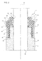
- the gasket 1 comprises an annular-shaped elastomeric element 21, and a supporting element 22 coaxially joined by means of a chemical-physical bond to the elastomeric element 21 itself to press the latter, in the radial direction with respect to axis B, onto the guide element 16 and onto the stem 16.
- the elastomeric element 21 is interposed between the supporting element 22 and the valve 2.
- the elastomeric element 21 firstly defines, proceeding along axis B towards the combustion chamber 5, a dynamic type sealing adapted to allow the passage of a minimum oil flow required to lubricate the coupling between the stem 16 and the guide element 15, and then a static type sealing to prevent a second oil seeping path towards the combustion chamber 5.
- the elastomeric element 21 is delimited by two axial ending, discoid sections 23, 24, opposite to each other, by an internal circumferential surface 25 adapted to partially cooperate with the stem 16 and partially with the guide element 15 to form the abovementioned seals, and by an external circumferential surface 26 adapted to couple with the supporting element 22 and with an annular elastic collar 27 as so to press the internal circumferential surface 25 onto the stem 16 and onto the guide element 15.
- the section 23 face the control mechanism 19 and is crossed by the stem 16; the section 24, under assembly conditions, faces the combustion chamber 5, and is crossed by both the stem 16 and the guide element 15.
- the internal circumferential surface 25 of the elastomeric element 21 comprises, in a position adjacent to the section 23, a minimum diameter section 28, adapted to be radially pressed by the elastic collar 27 against the stem 16 to define a circumferential, dynamic-type sealing line, which allows a minimum flow of oil to leak in virtue of the sliding coupling with the stem 16 itself.
- the internal circumferential surface 25 of the elastomeric element 21 comprises a substantially cylindrical portion 29, in a position adjacent to the section 24, adapted to be radially pressed by the supporting element 22 against the guide element 15 as so to define a static-type, cylindrical sealing area.
- the elastomeric element 21 further comprises a portion interposed between the section 28 and the portion 29, a further portion 30 overhangingly carrying a gas-tight lip 31 cooperating in use with the stem 16 of the valve 2.
- the lip 31 has a truncated-conical shape of axis B with a decreasing section in the direction opposite to the pressure forces generated by the gases crossing the pipe 12 and directed towards the section 28; in this illustrated case, the lip 31 has a decreasing section towards the portion 29.
- the lip 31 is connected to an internal circumferential surface of the portion 30 at the larger-section part thereof.
- Such a connection defines a sort of virtual hinge 42 between the lip 31 and the circumferential internal surface 25 of the elastomeric element 21.
- the portion 30 of the elastomeric element 21 has, on the side opposite to the lip 31 with respect to axis B, a surface 40 cooperating with a radially internal surface of a segment 41 of the supporting element 22.
- the portion 30 is advantageously shaped so that, no matter how two points belonging to the surface 40 are chosen, the segment joining such points is completely contained within the portion 30 itself.
- the portion 30 is free from the seats adapted to couple with respective portions of the segment 41 of the supporting element 22. Therefore, the segment 41 is not embedded, not even in part, in the portion 30 of the elastomeric element 21.
- the segment 41 further defines a first axial end of the supporting element 22.
- the supporting element 22 has a substantially cylindrical shape, elongated according to axis B, and comprises, in addition to segment 41:
- the segment 41 is also substantially parallel to the axis B, and the segment 44 cooperates with a surface of the elastomeric element 21 opposite and parallel to the surface 25.
- the supporting element 22 has radially dimensions increasing with respect to axis B, proceeding from its second axial end defined by the segment 43 towards its first axial end defined by the segment 41.
- the supporting element 22 embraces the portion 30 of the elastomeric element 21 without having portions embedded inside the portion 30 itself, the stiffness of the lip 31 with respect to the rotation about the virtual hinge 42 is ensured by the segment 41 of the supporting element 22 and by the shape of the portion 30, which has greater radial and axial dimensions than the known solutions.
- gasket 1 made according to the present invention allows to obtain are apparent from an examination of its features.
- the gasket 1 allows to effectively control the flow of lubricant oil to the combustion chamber 5 and to obtain an effective gas-tight effect without requiring to embed a segment of the supporting element 22 into a corresponding seat of the elastomeric element 21.
- the gasket 1 is particularly simple and cost-effective to be implemented while effectively performing its task of controlling the flow of lubricant oil to the combustion chamber 5.
Landscapes
- Engineering & Computer Science (AREA)
- Mechanical Engineering (AREA)
- General Engineering & Computer Science (AREA)
- Sealing With Elastic Sealing Lips (AREA)
- Exhaust-Gas Circulating Devices (AREA)
Claims (6)
- Joint (1) pour une soupape (2) d'un moteur à combustion interne (3) ; ladite soupape (2) comprenant un élément de guidage (15) définissant un siège traversant, et une tige (16) coulissant de manière mobile dans un tel siège ; ledit joint (1) comprenant :- un élément de support de forme tubulaire (22) selon un axe (B) monté de manière coaxiale sur ladite soupape (2) ; et- un élément élastiquement déformable (21) intercalé entre ledit élément de support (22) et ladite soupape (2) ;
ledit élément élastiquement déformable (21) comprenant, à son tour :- une première partie (28) adaptée pour coopérer avec ladite tige (16) de ladite soupape (2) et pour être radialement comprimée contre la tige (16) par un collier élastique (27) ;- une deuxième partie (29) adaptée pour coopérer avec une surface extérieure dudit élément de guidage (15) et pour être radialement comprimée contre l'élément de guidage (15) par ledit élément de support (22) ; et- une troisième partie (30) axialement interposée entre lesdites première et deuxième parties (28, 29), en portant de manière suspendue un rebord étanche au gaz (31) adapté pour coopérer avec ladite tige (16) de ladite soupape (2) et comprenant, du côté opposé audit rebord (31), une surface (40) adaptée pour coopérer avec une première région (41) dudit élément de support (22) définissant une première extrémité axiale de ce dernier ;dans lequel ledit rebord (31) a une forme conique tronquée coaxiale avec ledit axe (B) et avec une section décroissante vers ladite deuxième partie (29) de façon à s'opposer en cours d'utilisation aux forces de pression de gaz ;
caractérisé en ce que ladite troisième partie (30) est conformée de sorte que, peu importe comment deux points appartenant à la surface (40) sont choisis, le segment joignant lesdits points est totalement contenu dans la troisième partie (30) elle-même. - Joint selon la revendication 1, caractérisé en ce que ledit élément de support (22) comprend une seconde extrémité axiale opposée à ladite première extrémité axiale et définie par une deuxième région (43) correspondante ;
ledit élément de support (22) ayant des dimensions radiales relativement audit axe (B), en augmentation depuis ladite seconde extrémité axiale vers ladite première extrémité axiale. - Joint selon la revendication 1 ou 2, caractérisé en ce que ladite première région (41) est allongée parallèlement audit axe (B).
- Joint selon l'une quelconque des revendications précédentes, caractérisé en ce que ledit élément de support (22) comprend une troisième région (44) axialement intercalée entre lesdites première et deuxième régions (41, 43) et allongée parallèlement audit axe (B).
- Joint selon la revendication 4, caractérisé en ce que ladite troisième région (44) est jointe, à ses extrémités axiales, réciproquement opposées, auxdites première et deuxième régions (41, 43).
- Joint selon l'une quelconque des revendications 2 à 5, caractérisé en ce que ladite deuxième région (43) s'étend de manière transversale audit axe (B) et est au moins partiellement reçue dans un siège annulaire dudit élément élastiquement déformable (21).
Applications Claiming Priority (1)
| Application Number | Priority Date | Filing Date | Title |
|---|---|---|---|
| ITTO20070868 ITTO20070868A1 (it) | 2007-11-29 | 2007-11-29 | Guarnizione per una valvola di un motore a combustione interna |
Publications (2)
| Publication Number | Publication Date |
|---|---|
| EP2065573A1 EP2065573A1 (fr) | 2009-06-03 |
| EP2065573B1 true EP2065573B1 (fr) | 2011-01-12 |
Family
ID=40315050
Family Applications (1)
| Application Number | Title | Priority Date | Filing Date |
|---|---|---|---|
| EP20080170310 Active EP2065573B1 (fr) | 2007-11-29 | 2008-11-28 | Joint de soupape de moteur à combustion interne |
Country Status (3)
| Country | Link |
|---|---|
| EP (1) | EP2065573B1 (fr) |
| DE (1) | DE602008004409D1 (fr) |
| IT (1) | ITTO20070868A1 (fr) |
Families Citing this family (1)
| Publication number | Priority date | Publication date | Assignee | Title |
|---|---|---|---|---|
| ITTO20131018A1 (it) | 2013-12-13 | 2015-06-14 | Corcos Ind S A S Di Extern A Italia S R L | Guarnizione per una valvola di un motore a combustione interna |
Family Cites Families (13)
| Publication number | Priority date | Publication date | Assignee | Title |
|---|---|---|---|---|
| JPS5865372A (ja) * | 1981-09-18 | 1983-04-19 | ゲツツエ・アクチエンゲゼルシヤフト | リツプシ−ルリング |
| US4993379A (en) * | 1989-11-02 | 1991-02-19 | Rft S.P.A. | Sliding stem seal, particularly for valve stems |
| DE4119952A1 (de) * | 1991-06-18 | 1992-12-24 | Goetze Ag | Ventilschaftabdichtung |
| DE19709170C2 (de) * | 1997-03-06 | 1999-11-04 | Cr Elastomere Gmbh | Abdichtung für hin- und hergehende Maschinenteile, insbesondere Ventilschaftabdichtung |
| US6244235B1 (en) * | 2000-04-18 | 2001-06-12 | Dana Corporation | Heavy-duty valve stem seal assembly |
| US6450143B1 (en) * | 1999-09-14 | 2002-09-17 | Dana Corporation | Heavy-duty valve stem seal assembly |
| JP2003042301A (ja) * | 2001-08-01 | 2003-02-13 | Nok Corp | バルブステムシール |
| US6764079B1 (en) * | 2002-04-19 | 2004-07-20 | Dana Corporation | Valve seal assembly with straight-walled retainer |
| JP4123837B2 (ja) * | 2002-06-19 | 2008-07-23 | Nok株式会社 | バルブステムシール |
| US7025030B2 (en) * | 2003-08-21 | 2006-04-11 | Dana Corporation | Valve stem seal assembly with changeable cap |
| CN2705601Y (zh) * | 2004-04-14 | 2005-06-22 | 青岛基珀密封工业有限公司 | 弹簧座整体气门导杆油封 |
| DE602006015673D1 (de) * | 2006-12-29 | 2010-09-02 | Corcos Ind S A S Di Externa It | Ventilvorrichtung für einen Verbrennungsmotor mit einer zum Ventil koaxial angeordneten Dichtung |
| EP1939414B1 (fr) * | 2006-12-29 | 2013-02-13 | CORCOS INDUSTRIALE S.a.s. di Externa Italia S.r.l. | Joint d'une soupape dans un moteur à combustion interne |
-
2007
- 2007-11-29 IT ITTO20070868 patent/ITTO20070868A1/it unknown
-
2008
- 2008-11-28 DE DE200860004409 patent/DE602008004409D1/de active Active
- 2008-11-28 EP EP20080170310 patent/EP2065573B1/fr active Active
Also Published As
| Publication number | Publication date |
|---|---|
| DE602008004409D1 (de) | 2011-02-24 |
| EP2065573A1 (fr) | 2009-06-03 |
| ITTO20070868A1 (it) | 2009-05-30 |
Similar Documents
| Publication | Publication Date | Title |
|---|---|---|
| US7862048B2 (en) | Gasket for a valve in an internal combustion engine | |
| EP2884061B1 (fr) | Joint d'une soupape dans un moteur à combustion interne | |
| CA2836807C (fr) | Ensemble joint pour tige de soupape tolerant vis-a-vis de l'excentricite | |
| JP2012211593A (ja) | 内燃機関の弁用のガスケット | |
| US8764019B2 (en) | Gasket for a valve in an internal combustion engine | |
| EP3315830B1 (fr) | Ensemble joint d'étanchéité de chemise de cylindre à mouvement alternatif | |
| US10557389B2 (en) | Gasket for a valve of an internal combustion engine | |
| EP2065573B1 (fr) | Joint de soupape de moteur à combustion interne | |
| KR200488471Y1 (ko) | 내연기관의 밸브용의 개스킷 | |
| US10746062B2 (en) | Gasket with an improved heat dissipation capacity for a valve of an internal combustion engine | |
| US11242777B1 (en) | Gasket for a valve of an internal combustion engine | |
| CN107304691B (zh) | 用于内燃机的气门的衬垫 | |
| EP1582704A1 (fr) | Joint de queue de soupape |
Legal Events
| Date | Code | Title | Description |
|---|---|---|---|
| PUAI | Public reference made under article 153(3) epc to a published international application that has entered the european phase |
Free format text: ORIGINAL CODE: 0009012 |
|
| AK | Designated contracting states |
Kind code of ref document: A1 Designated state(s): AT BE BG CH CY CZ DE DK EE ES FI FR GB GR HR HU IE IS IT LI LT LU LV MC MT NL NO PL PT RO SE SI SK TR |
|
| AX | Request for extension of the european patent |
Extension state: AL BA MK RS |
|
| 17P | Request for examination filed |
Effective date: 20091203 |
|
| 17Q | First examination report despatched |
Effective date: 20100112 |
|
| AKX | Designation fees paid |
Designated state(s): DE FR GB |
|
| RAP1 | Party data changed (applicant data changed or rights of an application transferred) |
Owner name: CORCOS INDUSTRIALE S.A.S. DI EXTERNA ITALIA S.R.L. |
|
| GRAP | Despatch of communication of intention to grant a patent |
Free format text: ORIGINAL CODE: EPIDOSNIGR1 |
|
| GRAS | Grant fee paid |
Free format text: ORIGINAL CODE: EPIDOSNIGR3 |
|
| GRAA | (expected) grant |
Free format text: ORIGINAL CODE: 0009210 |
|
| AK | Designated contracting states |
Kind code of ref document: B1 Designated state(s): DE FR GB |
|
| REG | Reference to a national code |
Ref country code: GB Ref legal event code: FG4D |
|
| REF | Corresponds to: |
Ref document number: 602008004409 Country of ref document: DE Date of ref document: 20110224 Kind code of ref document: P |
|
| REG | Reference to a national code |
Ref country code: DE Ref legal event code: R096 Ref document number: 602008004409 Country of ref document: DE Effective date: 20110224 |
|
| PLBE | No opposition filed within time limit |
Free format text: ORIGINAL CODE: 0009261 |
|
| STAA | Information on the status of an ep patent application or granted ep patent |
Free format text: STATUS: NO OPPOSITION FILED WITHIN TIME LIMIT |
|
| 26N | No opposition filed |
Effective date: 20111013 |
|
| REG | Reference to a national code |
Ref country code: DE Ref legal event code: R097 Ref document number: 602008004409 Country of ref document: DE Effective date: 20111013 |
|
| REG | Reference to a national code |
Ref country code: DE Ref legal event code: R082 Ref document number: 602008004409 Country of ref document: DE Representative=s name: BOCKHORNI & KOLLEGEN PATENT- UND RECHTSANWAELT, DE Ref country code: DE Ref legal event code: R082 Ref document number: 602008004409 Country of ref document: DE Representative=s name: HEYER, VOLKER, DIPL.-PHYS. DR.RER.NAT., DE |
|
| REG | Reference to a national code |
Ref country code: DE Ref legal event code: R082 Ref document number: 602008004409 Country of ref document: DE Representative=s name: HEYER, VOLKER, DIPL.-PHYS. DR.RER.NAT., DE |
|
| REG | Reference to a national code |
Ref country code: FR Ref legal event code: PLFP Year of fee payment: 8 |
|
| REG | Reference to a national code |
Ref country code: DE Ref legal event code: R082 Ref document number: 602008004409 Country of ref document: DE Representative=s name: HEYER, VOLKER, DIPL.-PHYS. DR.RER.NAT., DE Ref country code: DE Ref legal event code: R081 Ref document number: 602008004409 Country of ref document: DE Owner name: FREUDENBERG SEALING TECHNOLOGIES S.A.S. DI EXT, IT Free format text: FORMER OWNER: CORCOS INDUSTRIALE S.A.S. DI EXTERNA ITALIA S.R.L., PINEROLO, IT |
|
| REG | Reference to a national code |
Ref country code: FR Ref legal event code: CD Owner name: CORCOS INDUSTRIALE S.A.S. DI EXTERNA ITALIA S., IT Effective date: 20160502 |
|
| REG | Reference to a national code |
Ref country code: FR Ref legal event code: PLFP Year of fee payment: 9 |
|
| REG | Reference to a national code |
Ref country code: FR Ref legal event code: PLFP Year of fee payment: 10 |
|
| P01 | Opt-out of the competence of the unified patent court (upc) registered |
Effective date: 20230524 |
|
| PGFP | Annual fee paid to national office [announced via postgrant information from national office to epo] |
Ref country code: DE Payment date: 20251126 Year of fee payment: 18 |
|
| PGFP | Annual fee paid to national office [announced via postgrant information from national office to epo] |
Ref country code: GB Payment date: 20251125 Year of fee payment: 18 |
|
| PGFP | Annual fee paid to national office [announced via postgrant information from national office to epo] |
Ref country code: FR Payment date: 20251124 Year of fee payment: 18 |